Drafting of various geometries using Chamfer, Fillet tool in AutoCad
Q1
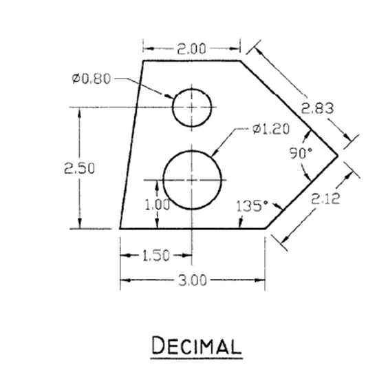
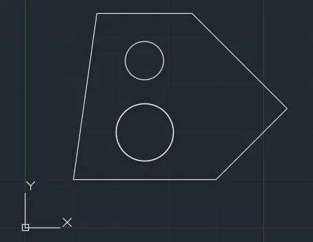
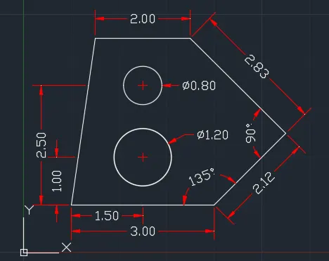
AIM : To draw the given figure using AutoCAD
PROCEDURE
STEP 1 :
Type drafting setting or OS in the command box and press enter
open snap and grid setting
Change snap spacing to 1
Change grid spacing to 1
Change major line every grid line to 5
Turn off adaptive grid and turn on display grid beyond limits
STEP 2 :
Type unit or UN in the command box and press enter
Set type of unit as decimal and precision as 0.00
In Insertion scale set unit as Millimetres
STEP 3 :
Type dimension style manager or D in the command box and press enter
Modify primary units as decimal and precision as 0.00
STEP 4 :
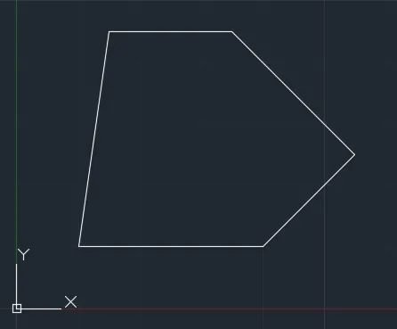
Type Polyline or PL in the command box and press enter
Specify start point: 1,1 and press enter
Specify next point : @3<0 and press enter
Specify next point : @2.12<45 and press enter
Specify next point : @2.83<135 and press enter
Specify next point : @2<180 and press enter
Specify next point : C (close the polyline) and press enter
STEP 5 :
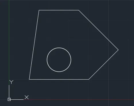
Type circle or C in the command box and press enter
Specify center point for circle : 2.5,2 and press enter
Specify radius of circle or [Diameter] : Press diameter and press enter
Specify diameter of circle : 1.2 and press enter
STEP 6 :
Type circle or C in the command box and press enter
Specify center point for circle : 2.5,3.5 and press enter
Specify radius of circle or [Diameter] : Press diameter and press enter
Specify diameter of circle : 0.8 and press enter
STEP 7 :
Type Dim in the command box and press enter
Add required dimensions to drawing
RESULT
The figure given is drawn using Polyline tool, circle tool, dimension tool and Relative polar co-ordinate system.
Q2
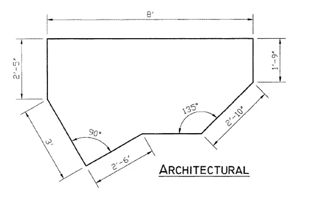
AIM : To draw the given figure using AutoCAD
PROCEDURE
STEP 1 :
Type drafting setting or OS in the command box and press enter
open snap and grid setting
Change snap spacing to 1
Change grid spacing to 1
Change major line every grid line to 5
Turn off adaptive grid and turn on display grid beyond limits
STEP 2 :
Type unit or UN in the command box and press enter
Set type of unit as architectural and precision as 0’-0”
In Insertion scale set unit as inches
STEP 3 :
Type dimension style manager or D in the command box and press enter
Modify primary units as architectural and precision as 0’-0”
STEP 4 :
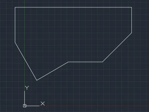
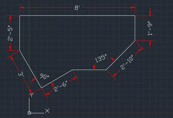
Type Polyline or PL in the command box and press enter
Specify start point : 3',3' and press enter
Specify next point : @2'6"<210 and press enter
Specify next point : @3'<120 and press enter
Specify next point : @2'5"<90 and press enter
Specify next point : @8'<0 and press enter
Specify next point : @1'9"<270 and press enter
Specify next point : @2'10"<225 and press enter
Specify next point : C (close the polyline) and press enter
STEP 5 :
Type Dim in the command box and press enter
Add required dimensions to drawing
RESULT
The figure given is drawn using Polyline tool, dimension tool and Relative polar co-ordinate system.
Q3
AIM : To draw the given figure using AutoCAD
PROCEDURE
STEP 1 :
Type drafting setting or OS in the command box and press enter
open snap and grid setting
Change snap spacing to 1
Change grid spacing to 1
Change major line every grid line to 5
Turn off adaptive grid and turn on display grid beyond limits
STEP 2 :
Type unit or UN in the command box and press enter
Set type of unit as engineering and precision as 0’-0.0”
In Insertion scale set unit as inches
STEP 3 :
Type dimension style manager or D in the command box and press enter
Modify primary units as engineering and precision as 0’-0.0”
STEP 4 :
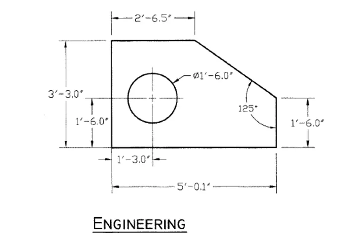
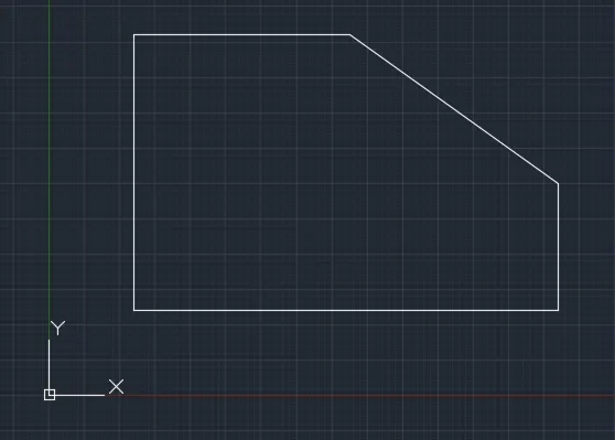
Type Polyline or PL in the command box and press enter
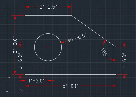
Specify start point : 3'6.5",4'3" and press enter
Specify next point : @2'6.5"<180 and press enter
Specify next point : @3'3"<270 and press enter
Specify next point : @5'0.1"<0 and press enter
Specify next point : @1'6"<90 and press enter
Specify next point : C (close the polyline) and press enter
STEP 5 :
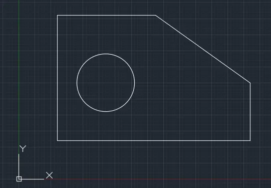
Type circle or C in the command box and press enter
Specify center point for circle : 2’3”,2’6” and press enter
Specify radius of circle or [Diameter] : Press diameter and press enter
Specify diameter of circle : 1’6” and press enter
STEP 6 :
Type Dim in the command box and press enter
Add required dimensions to drawing
RESULT
The figure given is drawn using Polyline tool, circle tool, dimension tool and Relative polar co-ordinate system.
Q4
AIM : To draw the given figure using AutoCAD
PROCEDURE
STEP 1 :
Type drafting setting or OS in the command box and press enter
open snap and grid setting
Change snap spacing to 1
Change grid spacing to 1
Change major line every grid line to 5
Turn off adaptive grid and turn on display grid beyond limits
STEP 2 :
Type unit or UN in the command box and press enter
Set type of unit as decimal and precision as 0.00
In Insertion scale set unit as Millimetres
STEP 3 :
Type dimension style manager or D in the command box and press enter
Modify primary units as decimal and precision as 0.00
STEP 4 :
Type Polyline or PL in the command box and press enter
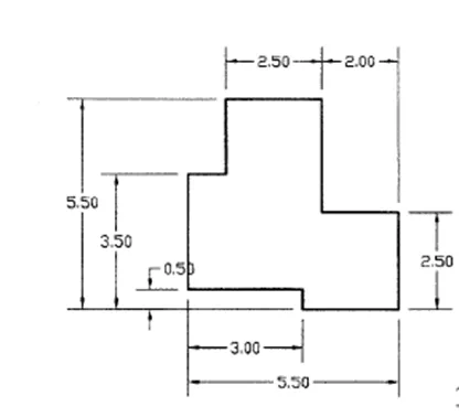
Specify start point : 1,1.5 and press enter
Specify next point : @3<0 and press enter
Specify next point : @0.5<270 and press enter
Specify next point : @2.5<0 and press enter
Specify next point : @2.5<90 and press enter
Specify next point : @2<180 and press enter
Specify next point : @3<90 and press enter
Specify next point : @2.5<180 and press enter
Specify next point : @2<270 and press enter
Specify next point : @1<180 and press enter
Specify next point : C (close the polyline) and press enter
STEP 5 :
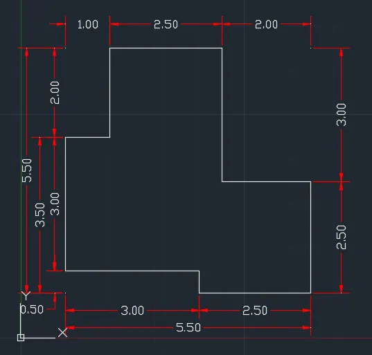
Type Dim in the command box and press enter
Add required dimensions to drawing
RESULT
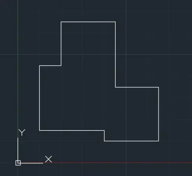
The figure given is drawn using Polyline tool, dimension tool and Relative polar co-ordinate system.
Q5
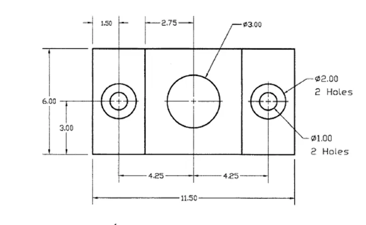
AIM : To draw the given figure using AutoCAD
PROCEDURE
STEP 1 :
Type drafting setting or OS in the command box and press enter
open snap and grid setting
Change snap spacing to 1
Change grid spacing to 1
Change major line every grid line to 5
Turn off adaptive grid and turn on display grid beyond limits
STEP 2 :
Type unit or UN in the command box and press enter
Set type of unit as decimal and precision as 0.00
In Insertion scale set unit as Millimetres
STEP 3 :
Type dimension style manager or D in the command box and press enter
Modify primary units as decimal and precision as 0.00
STEP 4 :
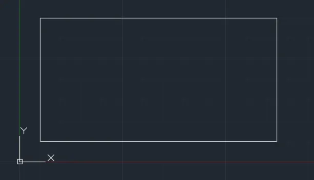
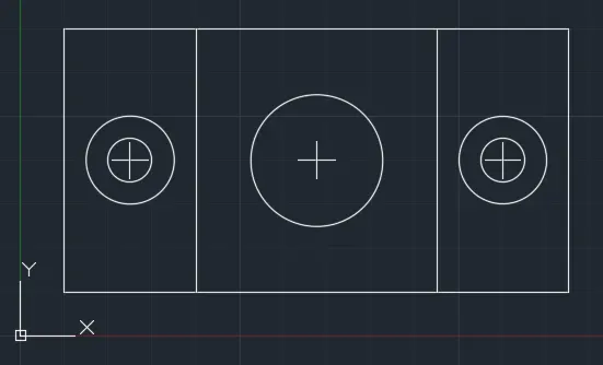
Type line or L in the command box and press enter
Specify first point: 1,1 and press enter
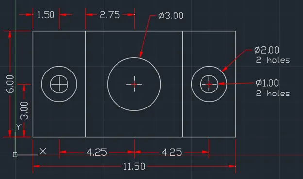
Specify next point : @11.5<0 and press enter
Specify next point : @6<90 and press enter
Specify next point : @11.5<180 and press enter
Specify next point : C (close the line) and press enter
STEP 5 :
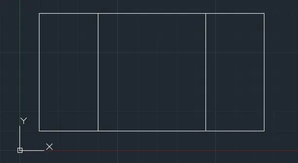
Type offset or O in the command box and press enter
Specify offset distance or [Through/Erase/Layer] : 3
Select object to offset : Exit the command
STEP 6 :
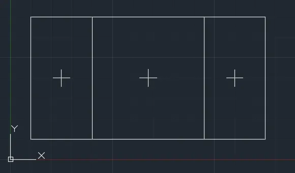
Type point or PO in the command box and press enter
Specify a point : 2.5,4 and press enter
Type point or PO in the command box and press enter
Specify a point : 6.25,4 and press enter
Type point or PO in the command box and press enter
Specify a point : 11,4 and press enter
STEP 7 :
Type circle or C in the command box and press enter
Specify center point for circle : select the point
Specify radius of circle or [Diameter] : Press diameter and press enter
Specify diameter of circle : 2 and press enter
Type circle or C in the command box and press enter
Specify center point for circle : select the point
Specify radius of circle or [Diameter] : Press diameter and press enter
Specify diameter of circle : 1 and press enter
Type circle or C in the command box and press enter
Specify center point for circle : select the point
Specify radius of circle or [Diameter] : Press diameter and press enter
Specify diameter of circle : 2 and press enter
Type circle or C in the command box and press enter
Specify center point for circle : select the point
Specify radius of circle or [Diameter] : Press diameter and press enter
Specify diameter of circle : 1 and press enter
Type circle or C in the command box and press enter
Specify center point for circle : select the point
Specify radius of circle or [Diameter] : Press diameter and press enter
Specify diameter of circle : 3 and press enter
STEP 8 :
Type Dim in the command box and press enter
Add required dimensions to drawing
RESULT
The figure given is drawn using line tool, offset tool, point tool, circle tool, dimension tool and Relative polar co-ordinate system.
Q6
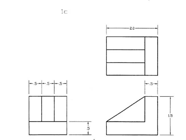
AIM : To draw the given figure using AutoCAD
PROCEDURE
STEP 1 :
Type drafting setting or OS in the command box and press enter
open snap and grid setting
Change snap spacing to 1
Change grid spacing to 1
Change major line every grid line to 5
Turn off adaptive grid and turn on display grid beyond limits
STEP 2 :
Type unit or UN in the command box and press enter
Set type of unit as decimal and precision as 0.0
In Insertion scale set unit as Millimetres
STEP 3 :
Type dimension style manager or D in the command box and press enter
Modify primary units as decimal and precision as 0.0
STEP 4 :
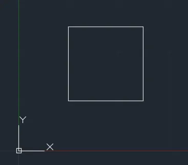
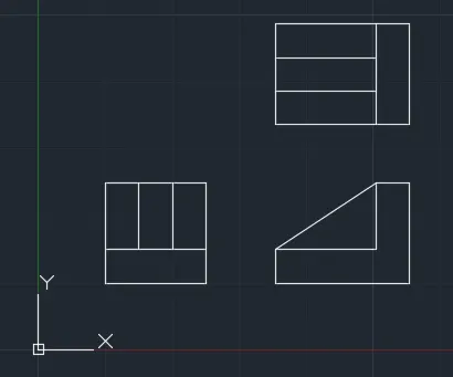
Type line or L in the command box and press enter
Specify first point : 1,1 and press enter
Specify next point : @1.5<0 and press enter
Specify next point : @1.5<90 and press enter
Specify next point : @1.5<180 and press enter
Specify next point : C (close the line) and press enter
STEP 5 :
Type copy or CO in the command box and press enter
Select base point : and place the copied object
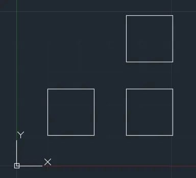
STEP 6 :
Type stretch or S in the command box and press enter
Select objects: Specify opposite corner
Specify second point : 0.5 and press enter
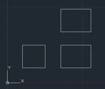
STEP 7 :
Type offset or O in the command box and press enter
Specify offset distance or [Through/Erase/Layer] : 0.5
Select object to offset : Exit the command
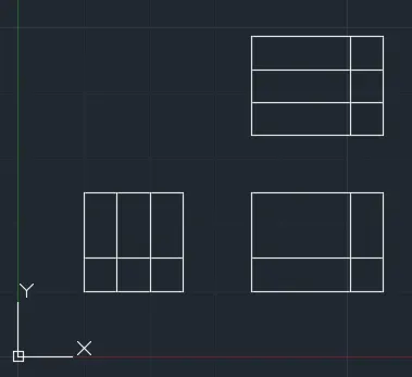
STEP 8 :
Type trim or TR in the command box and press enter
Select the object which needs to be trimmed
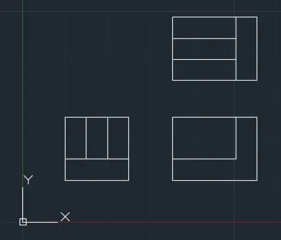
STEP 9 :
Type chamfer or CHA in the command box and press enter
(TRIM mode) Current chamfer Dist1 = 0.00, Dist2 = 0.00
Select first line : D (distance of chamfer) and press enter
Specify first chamfer distance : 1.5 and press enter
Specify second chamfer distance : 1 and press enter
Select first line : select and press enter
Select second line : select and press enter
STEP 10 :
Type Dim in the command box and press enter
Add required dimensions to drawing
RESULT
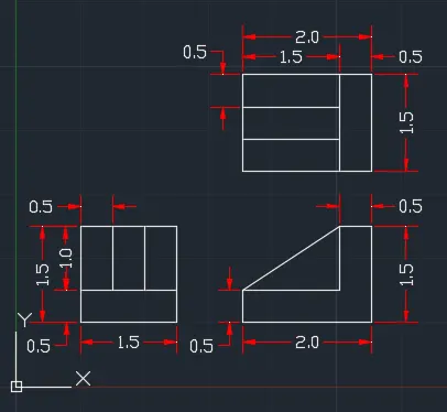
The figure given is drawn using line tool, copy tool, stretch tool, offset tool, chamfer tool, dimension tool and Relative polar co-ordinate system.
Q7
AIM : To draw the given figure using AutoCAD
PROCEDURE
STEP 1 :
Type drafting setting or OS in the command box and press enter
open snap and grid setting
Change snap spacing to 1
Change grid spacing to 1
Change major line every grid line to 5
Turn off adaptive grid and turn on display grid beyond limits
STEP 2 :
Type unit or UN in the command box and press enter
Set type of unit as decimal and precision as 0
In Insertion scale set unit as Millimetres
STEP 3 :
Type dimension style manager or D in the command box and press enter
Modify primary units as decimal and precision as 0
STEP 4 :
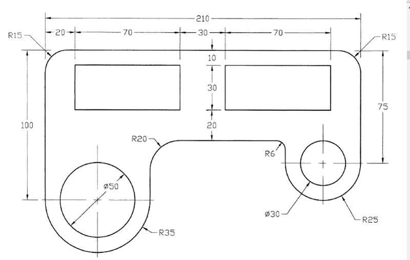
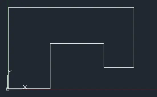
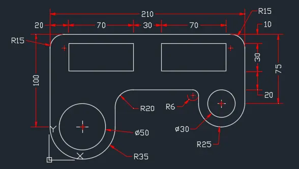
Type polyline or PL in the command box and press enter
Specify start point: 1,1 and press enter
Specify next point : @70<0 and press enter
Specify next point : @75<90 and press enter
Specify next point : @90<0 and press enter
Specify next point : @40<270 and press enter
Specify next point : @50<0 and press enter
Specify next point : @100<90 and press enter
Specify next point : @210<180 and press enter
Specify next point : C (close the polyline) and press enter
STEP 5 :
Type fillet or F in the command box and press enter
Current settings: Mode = TRIM, Radius = 0
Select first object : r (radius of the fillet)
Specify fillet radius : 15
Select first object : click on the first line
Select second object : click on the second line
Type fillet or F in the command box and press enter
Current settings: Mode = TRIM, Radius = 0
Select first object : r (radius of the fillet)
Specify fillet radius : 15
Select first object : click on the first line
Select second object : click on the second line
Type fillet or F in the command box and press enter
Current settings: Mode = TRIM, Radius = 0
Select first object : r (radius of the fillet)
Specify fillet radius : 20
Select first object : click on the first line
Select second object : click on the second line
Type fillet or F in the command box and press enter
Current settings: Mode = TRIM, Radius = 0
Select first object : r (radius of the fillet)
Specify fillet radius : 6
Select first object : click on the first line
Select second object : click on the second line
Type fillet or F in the command box and press enter
Current settings: Mode = TRIM, Radius = 0
Select first object : r (radius of the fillet)
Specify fillet radius : 35
Select first object : click on the first line
Select second object : click on the second line
Type fillet or F in the command box and press enter
Current settings: Mode = TRIM, Radius = 0
Select first object : r (radius of the fillet)
Specify fillet radius : 35
Select first object : click on the first line
Select second object : click on the second line
Type fillet or F in the command box and press enter
Current settings: Mode = TRIM, Radius = 0
Select first object : r (radius of the fillet)
Specify fillet radius : 25
Select first object : click on the first line
Select second object : click on the second line
Type fillet or F in the command box and press enter
Current settings: Mode = TRIM, Radius = 0
Select first object : r (radius of the fillet)
Specify fillet radius : 25
Select first object : click on the first line
Select second object : click on the second line
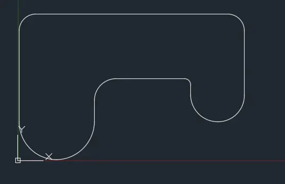
STEP 6 :
Type point or PO in the command box and press enter
Specify a point : 36,36 and press enter
Type point or PO in the command box and press enter
Specify a point : 186,61 and press enter
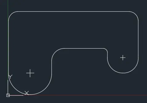
STEP 7 :
Type circle or C in the command box and press enter
Specify center point for circle : select the point
Specify radius of circle or [Diameter] : Press diameter and press enter
Specify diameter of circle : 50 and press enter
Type circle or C in the command box and press enter
Specify center point for circle : select the point
Specify radius of circle or [Diameter] : Press diameter and press enter
Specify diameter of circle : 30 and press enter
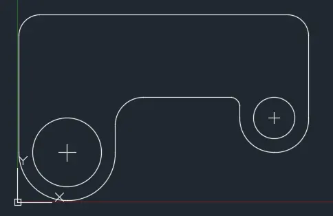
STEP 8 :
Type rectangle or REC in the command box and press enter
Specify first corner point : 21,96 and press enter
Specify other corner point : @70,30 and press enter
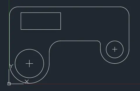
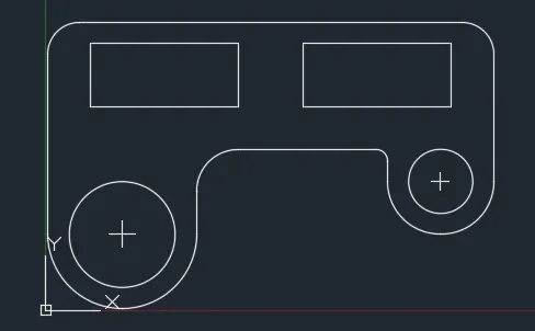
STEP 9 :
Type mirror or MI in the command box and press enter
Select the rectangle and mirror it towards right
STEP 10 :
Type Dim in the command box and press enter
Add required dimensions to drawing
RESULT
The figure given is drawn using polyline tool, fillet tool, point tool, circle tool, rectangle tool, mirror tool, dimension tool and Relative polar co-ordinate system.
Q8
AIM : To draw the given figure using AutoCAD
PROCEDURE
STEP 1 :
Type drafting setting or OS in the command box and press enter
open snap and grid setting
Change snap spacing to 1
Change grid spacing to 1
Change major line every grid line to 5
Turn off adaptive grid and turn on display grid beyond limits
STEP 2 :
Type unit or UN in the command box and press enter
Set type of unit as decimal and precision as 0
In Insertion scale set unit as Millimetres
STEP 3 :
Type dimension style manager or D in the command box and press enter
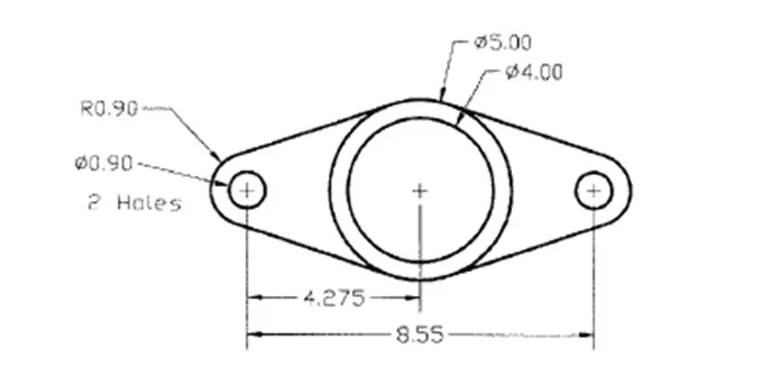
Modify primary units as decimal and precision as 0
STEP 4 :
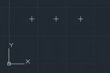
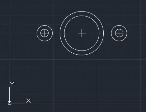
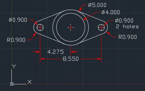
Type point or PO in the command box and press enter
Specify a point : 4,8 and press enter
Type point or PO in the command box and press enter
Specify a point : 8.275,8 and press enter
Type point or PO in the command box and press enter
Specify a point : 12.55,8 and press enter
STEP 5 :
Type circle or C in the command box and press enter
Specify center point for circle : select the point
Specify radius of circle or [Diameter] : Press diameter and press enter
Specify diameter of circle : 0.9 and press enter
Type circle or C in the command box and press enter
Specify center point for circle : select the point
Specify radius of circle or [Diameter] : Press diameter and press enter
Specify diameter of circle : 0.9 and press enter
Type circle or C in the command box and press enter
Specify center point for circle : select the point
Specify radius of circle : 0.9 and press enter
Type circle or C in the command box and press enter
Specify center point for circle : select the point
Specify radius of circle : 0.9 and press enter
Type circle or C in the command box and press enter
Specify center point for circle : select the point
Specify radius of circle or [Diameter] : Press diameter and press enter
Specify diameter of circle : 4 and press enter
Type circle or C in the command box and press enter
Specify center point for circle : select the point
Specify radius of circle or [Diameter] : Press diameter and press enter
Specify diameter of circle : 5 and press enter
STEP 6 :
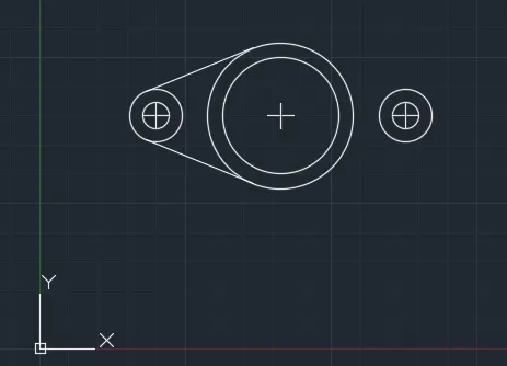
Type line or L in the command box and press enter
Specify first point : tan and press enter, select the outer circle at the top
Specify next point or [Undo]: tan and press enter, select the outer circle at the top
Type line or L in the command box and press enter
Specify first point : tan and press enter, select the outer circle at the top
Specify next point or [Undo]: tan and press enter, select the outer circle at the top
STEP 7 :
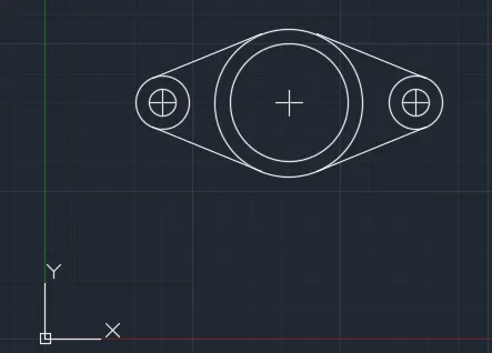
Type mirror or MI in the command box and press enter
Select the rectangle and mirror it towards right
STEP 8 :
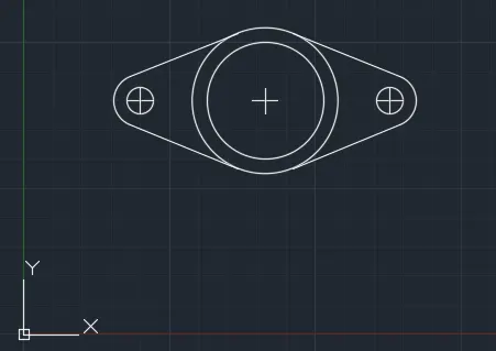
Type trim or TR in the command box and press enter
Select the object which needs to be trimmed
STEP 9 :
Type Dim in the command box and press enter
Add required dimensions to drawing
RESULT
The figure given is drawn using point tool, circle tool, line tool, trim tool, mirror tool and dimension tool
Q9
AIM : To draw the given figure using AutoCAD
PROCEDURE
STEP 1 :
Type drafting setting or OS in the command box and press enter
open snap and grid setting
Change snap spacing to 1
Change grid spacing to 1
Change major line every grid line to 5
Turn off adaptive grid and turn on display grid beyond limits
STEP 2 :
Type unit or UN in the command box and press enter
Set type of unit as engineering and precision as 0’-0”
In Insertion scale set unit as inches
STEP 3 :
Type dimension style manager or D in the command box and press enter
Modify primary units as engineering and precision as 0’-0”
STEP 4 :
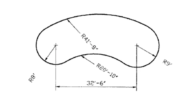
Type point or PO in the command box and press enter
Specify a point : 10’,10’ and press enter
Type point or PO in the command box and press enter
Specify a point : 42’-6”,10’ and press enter

STEP 5 :
Type circle or C in the command box and press enter
Specify center point for circle : select the point
Specify radius of circle : 8’ and press enter
Type circle or C in the command box and press enter
Specify center point for circle : select the point
Specify radius of circle : 9’ and press enter

STEP 6 :
Type circle or C in the command box and press enter
Specify center point for circle : Ttr
Specify point on object for first tangent of circle: select the first circle
Specify point on object for second tangent of circle: select the second circle
Specify radius of circle : 41'8" and press enter
STEP 7 :
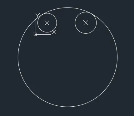
Type circle or C in the command box and press enter
Specify center point for circle : Ttr
Specify point on object for first tangent of circle: select the first circle
Specify point on object for second tangent of circle: select the second circle
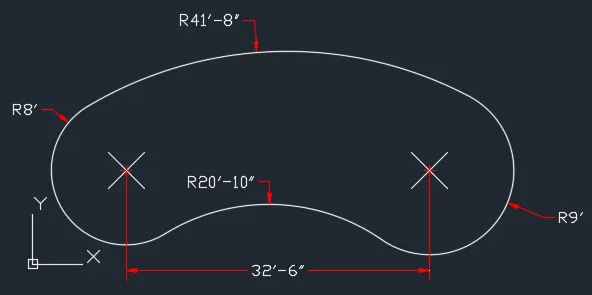
Specify radius of circle : 20'10" and press enter

STEP 8 :
Type trim or TR in the command box and press enter
Select the object which needs to be trimmed

STEP 9 :
Type Dim in the command box and press enter
Add required dimensions to drawing
RESULT
The figure given is drawn using point tool, circle tool, trim tool and dimension tool
Q10
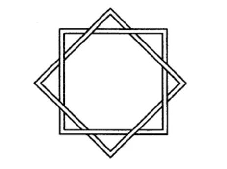
AIM : To draw the given figure using AutoCAD
PROCEDURE
STEP 1 :
Type drafting setting or OS in the command box and press enter
open snap and grid setting
Change snap spacing to 1
Change grid spacing to 1
Change major line every grid line to 5
Turn off adaptive grid and turn on display grid beyond limits
STEP 2 :
Type unit or UN in the command box and press enter
Set type of unit as engineering and precision as 0’-0”
In Insertion scale set unit as inches
STEP 3 :
Type dimension style manager or D in the command box and press enter
Modify primary units as engineering and precision as 0’-0”
STEP 4 :
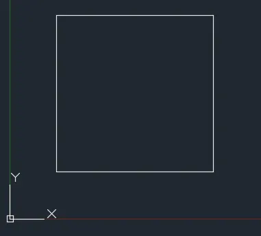
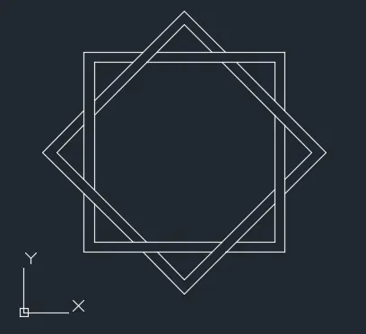
Type polygon or POL in the command box and press enter
Enter number of sides : 4 and press enter
Specify center of polygon : 8',8' and press enter
Enter an option : C(Circumscribed about circle) and press enter
Specify radius of circle : 5' and press enter
STEP 5 :
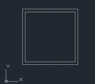
Type offset or O in the command box and press enter
Specify offset distance : 6" and press enter
Specify point on side to offset : Select the polygon and move the cursor inside
STEP 6 :
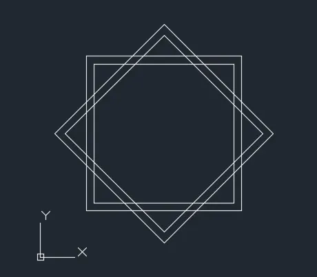
Type rotate or RO in the command box and press enter
Specify base point: select the midpoint of the polygon
Specify rotation angle or [Copy/Reference] : C (Rotating a copy of the selected objects)
Specify rotation angle : 45 degree
STEP 7 :
Type trim or TR in the command box and press enter
Select the object which needs to be trimmed
RESULT
The figure given is drawn using polygon tool, offset tool, rotate tool and trim tool
Q11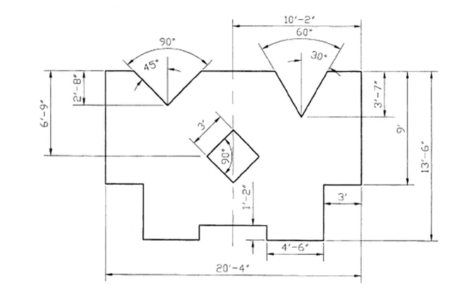
AIM : To draw the given figure using AutoCAD
PROCEDURE
STEP 1 :
Type drafting setting or OS in the command box and press enter
open snap and grid setting
Change snap spacing to 1
Change grid spacing to 1
Change major line every grid line to 5
Turn off adaptive grid and turn on display grid beyond limits
STEP 2 :
Type unit or UN in the command box and press enter
Set type of unit as engineering and precision as 0’-0”
In Insertion scale set unit as inches
STEP 3 :
Type dimension style manager or D in the command box and press enter
Modify primary units as engineering and precision as 0’-0”
STEP 4 :
Type polyline or PL in the command box and press enter
Specify start point: 4',1' and press enter
Specify next point : @4'6"<0 and press enter
Specify next point : @1'2"<90 and press enter
Specify next point : @5'4"<0 and press enter
Specify next point : @1'2"<270 and press enter
Specify next point : @4'6"<0 and press enter
Specify next point : @4'6"<90 and press enter
Specify next point : @3'<0 and press enter
Specify next point : @9'<90 and press enter
Specify next point : @20'4"<180 and press enter
Specify next point : @9'<270 and press enter
Specify next point : @3'<0 and press enter
Specify next point : C (close the polyline) and press enter
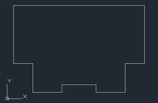
STEP 5 :
Type point or PO in the command box and press enter
Specify a point : 11’2”,8’4” and press enter
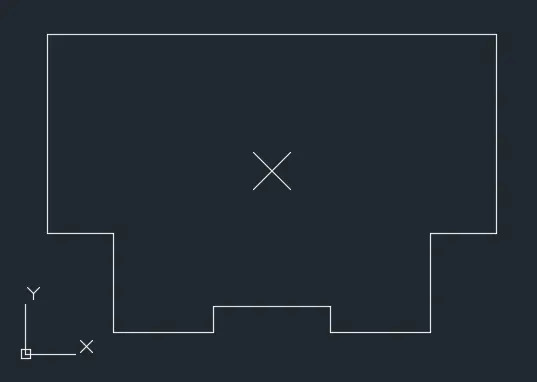
STEP 6 :
Type polygon or POL in the command box and press enter
Enter number of sides : 4 and press enter
Specify center of polygon : select the point and press enter
Enter an option : I(Inscribed about circle) and press enter
Specify radius of circle : 3' and press enter
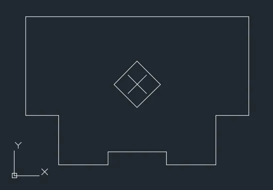
STEP 7 :
Type line or L in the command box and press enter
By using line command complete the drawing
STEP 8 :
Type trim or TR in the command box and press enter
Select the object which needs to be trimmed
STEP 9 :
Type Dim in the command box and press enter
Add required dimensions to drawing
RESULT
The figure given is drawn using polygon tool, polyline tool, line tool, trim tool, dimension tool and relative polar co-ordinate system