Week 3:- BiW Fixture Design Methodologies Challenges
Design Methodology
Design methodolgy is a study of product development or system for a unique situation, and it divided into 4 catagories.
- Purchase order
- Inputs from customer
- Percentage completion criteria
- Design output
1. Purchase Order
Purchase order is a commericial document from customer to confirm the order to start the work. Purchase order have detail about the project, valuve of project, delivery payment terms.
2. Inputs from customer
Inputs from customer majorily have following datas:
- Functional Requirements
- Preferred Standard Components
- Car Products
- Ergo Data
- Weld Study
- Standard Detailing Templates
3. Percentage completion criteria
Percentage completion criteria is followed in the design stages and dispatch stages of fixture. Through this percentage we can recognise the project's current stage.
- 0-25% - Input and Concept Design
- 25-40% - Concept approval and simulation check
- 40-85% - Design Freezing Detailing
- 85-100% - Check and Final Dispatch
4. Design output
In this stage fixture is get output as a 3D- Model and 2D drawing of tools to hand over to the customer. Drawings are divided into two types. Key sheet and LayoutSheet.
Unitized tools have more number of components so they need both key sheets and layouts.
Non-unitized tools have only one component thus a layout sheet is enough to detail completely.
Inputs required from the customer to start designing a Fixture
- Functional Requirements
- Preferred Standard Components
- Car Products
- layout
- Ergo Data
- Weld Study
- Standard Detailing Templates
Functional Requirements
Functional requirement is a detail about which type of fixture need to be deisgned.
- Welding Fixture
- Hemming Fixture
- Checking Fixture and
- Storage rack
Preferred Standard Components
In this customer input will allow as us know what type or which companies standard products we should use while designing a fixture. We should us as much as possible giving standard parts this will help in maintenance and for spare parts.
- Standard part suppling companies ABB,NAAMS,Destaco,Zytran,Tunkers,SMC,Festo
- Standard parts like Riser,s L Blocks, Retainer and Locator pins
- Components like Clamps, Cylinders, Slides, Switches and sensors
- Weld Guns, Tip Dressers, Tool Changers.
Car Products
Car Products like
- GD&T
- Part List
- CAD file of car parts
- Clamp Plan
- Product Assembly Process Sheet
1. GD & T stands for Geometric Dimensioning and Tolerancing.It is a symbolic language used by designers to communicate manufacturing constraints and tolerances clearly.
It provides informations of
- locating pins, Rest, Clamp, Dumps & slide information of each station.
- Sequence of opening of clamps, dumps & slide stoke information.
2.Part List
It provides detail information of parts which are used in assembled in fixture. It consists of part name, part number, part thickness and number revision part under gone.
3.CAD file of car parts
CAD file of parts which are used in assembly in file formats like .stp , .iges etc.
4.Clamp Plan
It provides the detail where we can place clamp unit, Rest unit and pin unit. refer figure 3.01
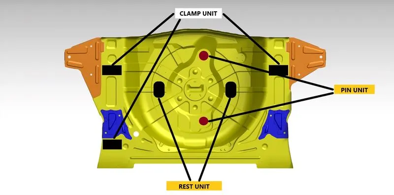
Figure 3.01
5.Product Assembly Process Sheet
It provide the process flow of assembly line in which station which parts will be assembled. It is very import input from customer and we can't change the process flow without customer's approval.
Refer figure 3.02 example of process sheet of underbody.
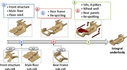
Figure 3.02
Clamp plan
It provides the detail where we can place clamp unit, Rest unit and pin unit. refer figure 3.01.
It will help us to avoid miss placing of clamp unit and rest unit which may cause damge to part. We can't change the clamp plan without asking permission from the customer.
Purpose of a Layout
Layout will provide information about plan view of assembly line. Through this layout we can get knowledge about process flow direction or conveyor direction, space constraints, no of robots used etc.,.
refer figure 3.03 example of layout drawing.
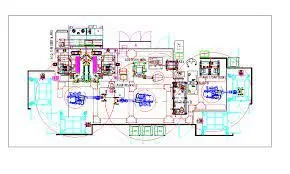
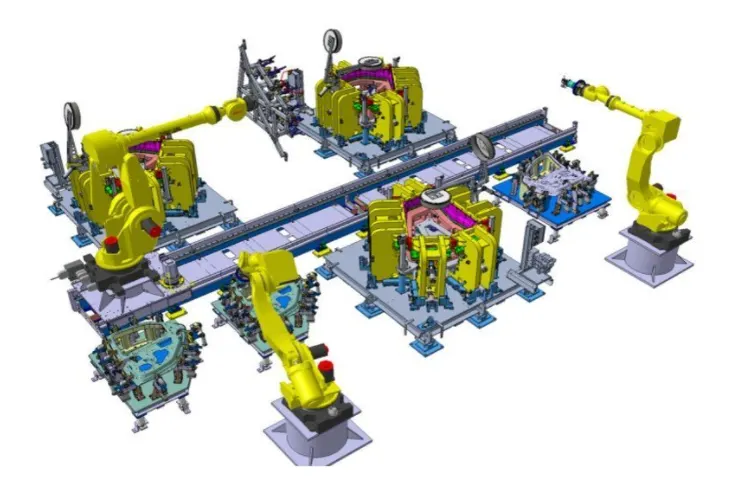
Figure 3.03
Following are major information we get from layout:
- Flow of parts
- Station Pitch
- Robot Stations
- Accessories like tool changer and dip dresser
- Sub Assembly links
- Platform Height
- Loading and Unloading sequence.
Ergo data
Ergo data is about the human body's responses to physical and physiological work demands. Repetitive work may cause strain, injuries to human bodies. To avoid these causes ergo data is necessary to considered in design.
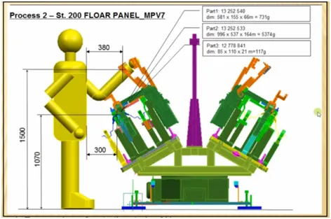
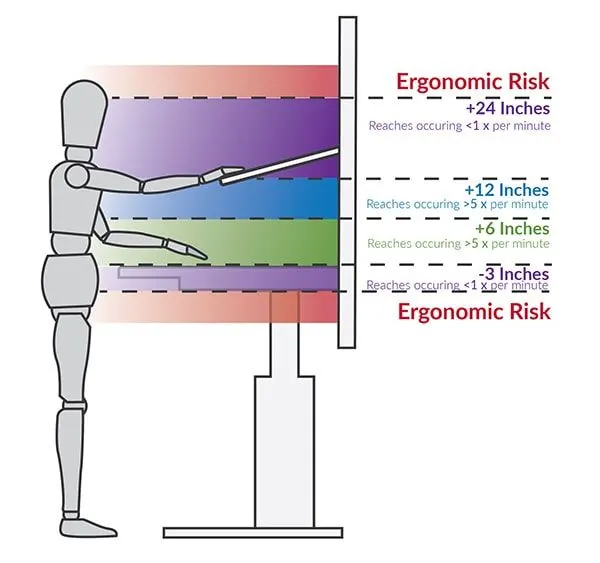
- Ergonomics referes to the study of human behaviour and movements
- Its proves information about standard loading height, working safety zone of operator.
Weld study
It is a study about welding process invloved, number of welding invloved and type of welding. and through this study we have get information about weld gun used, weld points.
There are two type weld point used in BIW assembly line
- Geo Weld Point
- Re-spot weld point
Weld Matrix
-It provides the X and Y co-ordinates of welding point.
Criteria for percentage completion
Percentage completion criteria is followed in the design stages and dispatch stages of fixture. Through this percentage we can recognise the project's current stage.
- 0-25% - Input and Concept Design
It means input from customer is gathered and conceptual design was designed.
- 25-40% - Concept approval and simulation check
Concept drawing are submited and passed to simulation check.
- 40-85% - Design Freezing Detailing
After checking with simulation and if all are as per requirement the design will be freezed and detail drawing is done. we can't change the design after it is freezed.
- 85-100% - Check and Final Dispatch
Once the detailing is done it will be released for qulaity inspection and dispatced after it passes the quality check.
Output in design
In this stage fixture is get output as a 3D- Model and 2D drawing of tools to hand over to the customer. Drawings are divided into two types. Key sheet and LayoutSheet.
Unitized tools have more number of components so they need both key sheets and layouts.
Non-unitized tools have only one component thus a layout sheet is enough to detail completely.
The output should compile following Points
- Approved Standrad parts should be used as much as possible.
- Design should simple and easy to understand
- Design should be less expensive.
- Design should be easy to handle and free from handling damage
- Adequate error proofing provision shim plates, sensors and rought locators should be considered .
- The weight of moving parts should me minimised and maintain maximum strength.
- Designer must be responsible to validate all weld guns and clamps
- Motion Control (stopper or sensor) should me considered.
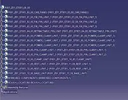
Structuring a design tree
This helps us to avoid the errors during design study, manufacturing, assembly, inspection etc. If the parts or assemblies are not properly or the design tree is not structures properly, it will create confusion to understand the design & may create major possibilities of making an errors.
Name for Parts and assemblies should is name in standard manner.
For Example:
Project No.-Name of Panel-Jig No.-Part No.-Component No.
It will help us to identify the quantity of items of same type or different types that are used in an assembly.
Example for Strcturing Design Tree.
Units
A Small machine or part of a machine that has a particular purpose.
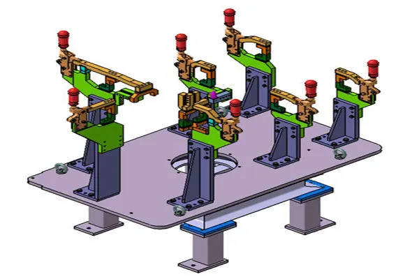
Different type of Units used in BIW Fixture
-Fixed Pin Unit
-Rest Unit
-Rough Locators
-Base Unit
-Slide Unit
Different parts of a fixed Unit
These are following fixed unit used in BIW Fixture
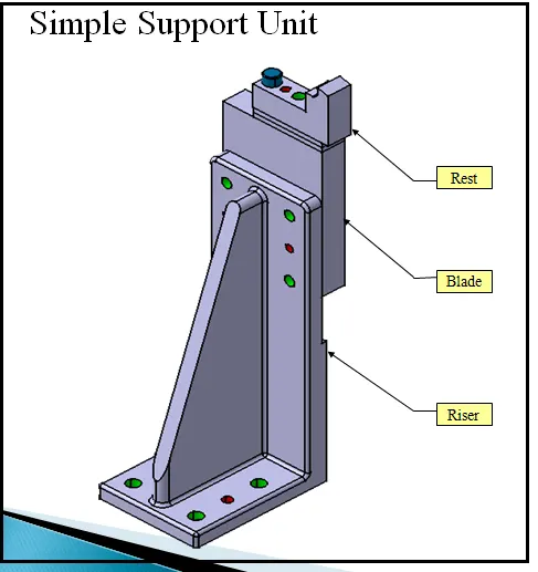
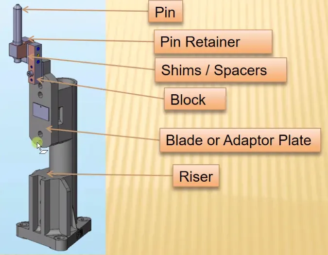
- Riser
- Blades
- Shims
- Locating Pins
- Pin Retainers
1. Riser
These are the standrad part which is used to increase the height of the unit
2. Blades
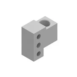
These are the plate which are used to mount the cylinders, sensor brackets and arms.
3.Shims
Shims are used maintain the dimesions of units for accurate mounting. Usually Pin units required 2 axis Shims (refer.Figure 3.04)
and clamp unit required in only one axis.
Shims are comes in different thickness 0.1mm to 5mm etc., as per requirements.(refer Figure 3.05)
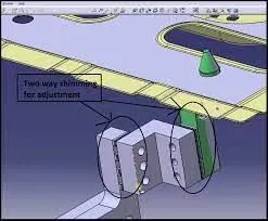
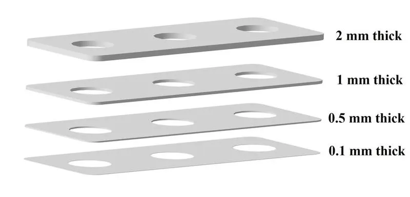
Figure 3.04 Figure 3.05
4.Locating Pins
Locating pins are used for controlled, fine tolerance positioning of a work piece.
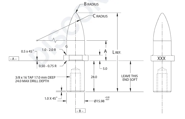
For example, a pallet that is moved along one axis, where the drive mechanism is not accurate and stable enough to place it in a position sufficiently accurate to execute a particular process, the use of locating pins may be the best solution.Usually two locating pins are enough to properly locate the work piece on one plane.
5.Pin Retainers
Pin retainers are used to hold the pins.
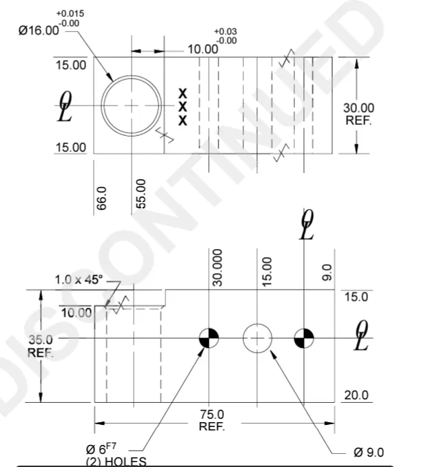
Purpose of making a Rest unit
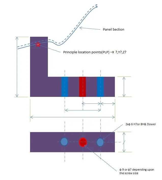
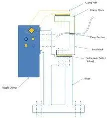
Rest units are used to support the car panel by using mylar or rest.
Parts of rest units are:
1) NC Block
2)Spacer
3)Blade
4)Riser
NC Block
Below image is a reference for mylar. This will hold the car panel. It will be fixed in top and bottom of to hold the panel. The top mylar is called clamping mylar and bottom mylar is called rest mylar.
2)Spacer or Shims
Shims are used maintain the dimesions of units for accurate mounting. Usually Pin units required 2 axis Shims (refer.Figure 3.04)
and clamp unit required in only one axis.
Shims are comes in different thickness 0.1mm to 5mm etc., as per requirements.(refer Figure 3.05 & 3.06)

Figure 3.06
3) Blade
These are the plate which are used to mount the cylinders, sensor brackets and arms. (refer Figure 3.07)
Figure 3.07
4)Riser
These are the standrad part which is used to increase the height of the unit.(refer Figure 3.07)
Basic fundamentals to design a Sensor unit
A Sensor unit is a unit which is designed to sense the presence of car panel. The sensors will transmit the signal to PLC Panels to start the next step.
- Each panel which are being welded in a tool should be sensed.
- Each and every panels should be sensed with the help of 1 or 2 sensors depending upon the size.
- Every sensor should be fixed with three direction adjustable way.
The following are different type of sensors used in industries:
1) Proximity Sensor (Refer (3.08)
2) Photoelectric Sensor (Refer 3.09)
3) Laser sensor (Refer 3.10)
These sensors are selected as per the possible sensing distance.
OMRON, SICK, IFM and AUTONICS are major sensor manufactures.
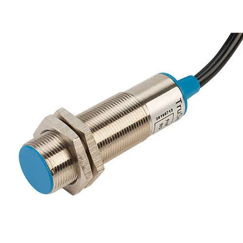
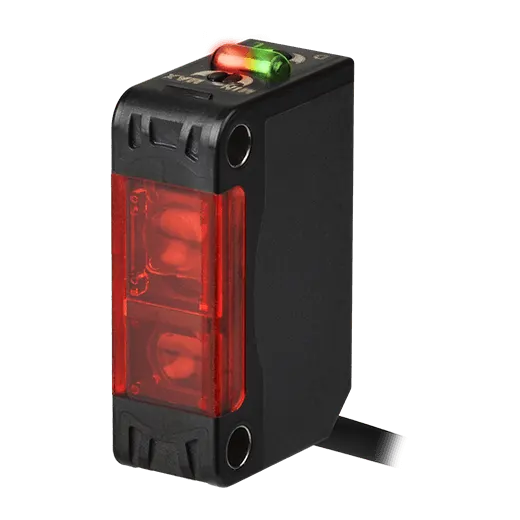
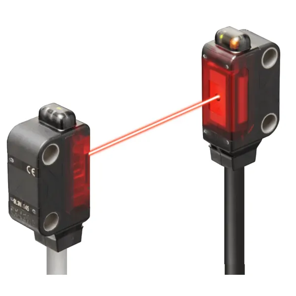
Figure 3.08 Figure 3.09 Figure 3.10
Rough locator unit
Rough Locator is a part designed to guide operator to locate the panel on to the pins accordingly.
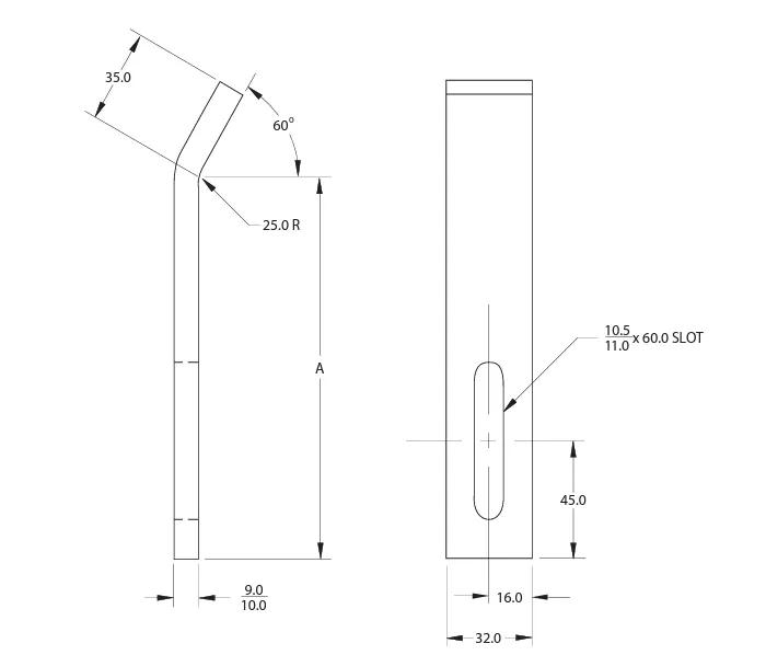
Figure 3.11
Fundamentals of Rough locators
- Rough locator should be placed at the edges of the car panel
- Rough locator has to be placed in the same angle of the panel edge with a min distance of 2mm-5 mm to the edge of panel.
- It should be guide the panel to pin arresting direction.
- It should start guiding the panel before 10 to 15mm to the start of the pin engagement.
- Rough locator should have entry angle for the panel. 30-45deg.
- Rough locator should be designed with two slots to mount the easy adjustments. The slots should be in the direction of car part guiding
Base Unit
A Base Unit is the unit in which all the units and parts are mounted. Necessary tools like pneumatic valve box, trunking cable path also mounted on the base unit.
Base unit will have the following parts
1) Foor plate- This help to fix or anchor the fixture to the ground.
2) Pedastal - It is a base or support for the fixture
3)Eye Bolt - It will help us to lift the base unit and also tie with the cable or ropes to the strcture.
4) Measuring Hole cover- In plate some of the holes drilled to take reference from the hole to other units. These holes are covered to prevent from dust depostion.
5) Valve Box - In vlave box different solenoid valve are kept which are used to operate the pneumatic cylinder. A vlave box should have one input and one output.
6) Base Plate - It is a heavier thickness plate which surfaces will be machined to maintain the paralleity for accurate to maintain the accuracy of fixture. It will carries all the weight of the mounted parts. It also have drilles to mount the different units.
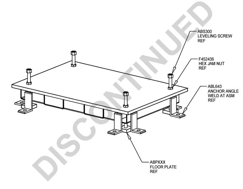
Figure 3.12
Dump Unit
It is a complex unit. Due to the space constrain we have adjust all the parts for available space. It consist of Dump Cylinder for clamping and unclamping operation.
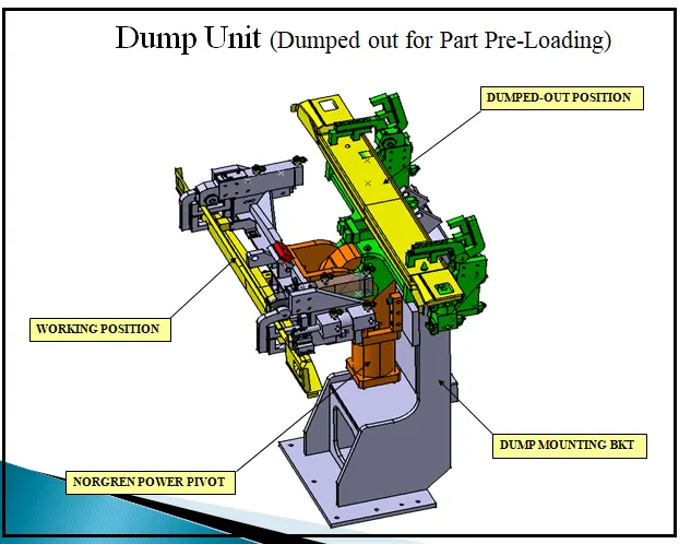
Figure 3.13
Slide unit
Slide unit are normaly a positioning unit. Which is used to position the fixture, weld gun, robots.
Slide Unit commonly have following parts:
1) Sliding mechanism - It can be cylinder or linear robots.
2) Sensor Unit - Sensor will give a feedback to the PLC panel about opened and closed condition.
3) Stopper Block - Every sliding unit should have a stopper block for safety purpose.
4) Position Lock unit - It will hold the position till the operation is done.
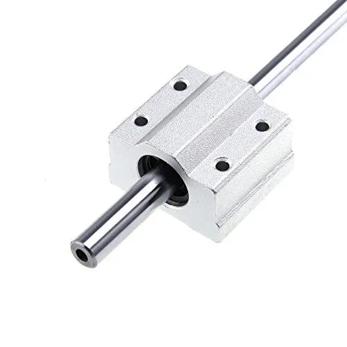
5) Guide Block - It is a unit which guide from one position to another position.
6) Guide Rail - Guide Rail is rail in which guide block will slide. It will have good surface finish to prevent friction.
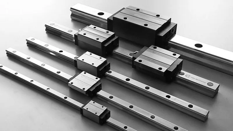
Figure 3.14 (Guide Block and Guide rail) also know as LM Guide.