Week 2:- BiW Fixture Basics Challenge
Project execution
Project execution is about actualizing the already designed plan. It involves putting into action all the activites that were set in the processes of project cycle. During these stage all the prepared schedules, procedures are used. Unplanned and unexpected events are taken care of in advance. It should be noted that working within in the scope of the project.
The objectives of Project execution process are to:
- Make Sure the project carried out as planned
- Assemble the team which are invloving in project and monitor them during project execution
- Ensure that project team is managed effectively so that performance is utlilzied and all problems are addressed
- Ensure that there is no communication gap between team and member.
The step by step process of project activites in below Figure 2.01
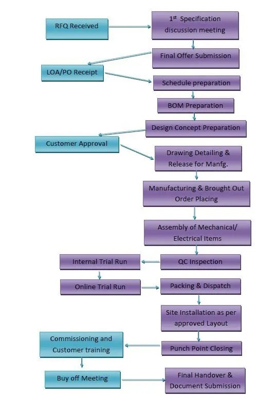
Figure 2.01
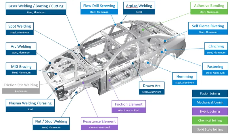
Joining Process
Join is a manufacuring process in which two similar or differnent type of material or part assembled together by welding or glueing or riviting or bolting for permanently or temporarily.
There are two major type of joining Process
- Mechanical Joining
- Metallurgical Joining
1.) Mechanical Joining
Joining Process includes bolting, riveting and folding all of which join by mechanical Forces
Figure 2.02 shows different type of mechanical joining
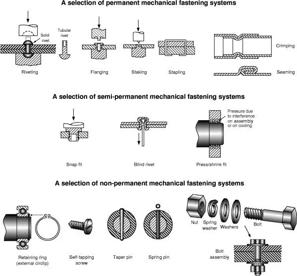
Figure 2.02
2)Metallurgical Joining
If the joining process carried out by using differnt type of engeries like electical energy, chemical energy. The following are examples of metallurgical joining process arc welding, resistance welding, seam welding, spot welding,friction welding blazing and slodering.
Figure 2.03 shows welding process.
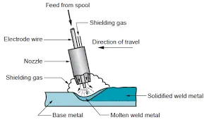
Figure 2.03
Resistance Welding
Resistance welding is the process in which two are more parts welded by use of heat and pressure. The heat in resistance welding process is generated by the resistance offered by the work piece to the flow of electric current.
The resistance welding includes spot welding, seam welding and projection welding.
Figure 2.04 example of resistance welding
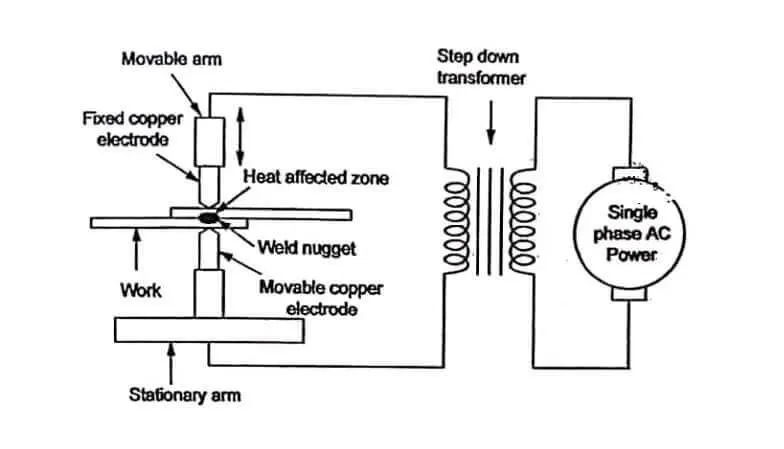
Figure 2.04
Advantages
- No required of filler rod
- Higher producion rate
- Automation and mechanization is simple.
Disadvantages
- Butt Welding is not possible
- Cost is high.
Application of Resistance welding in Automotive sector
- Automotive body panel have more number of welding spot hence requied higher weldng speed.
- Resistance welding are easier to automation.
- Achieving consistent quality by using spot welding systems
Figure 2.05 example of resistance welding in automotive industry

Figure 2.05
Fusion Welding
Fusion Welding is the process in which two part or metal joing by heating them to melting point. The process may or may not required filler rod.
Figure 2.06 example of Fusion welding
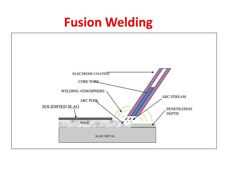
Figure 2.06
Type of fusion welding are
- Sheilded metal Arc Welding
- Plasma Arc Welding
- TIG Welding (Tungsten Inert Gas)
- MIG Welding (Metal Inet Gas)
3-2-1 Principle
There are 12 degrees of freedom for a free body. 6 translational degrees of freedom and 6 rotational degrees of freedom.3-2-1 priciple is widely used in fixture. In this principle we can arrest all 12 degrees of freedom effectivley. 6 translation degrees of freedom are +X,+Y,+Z in postive direction X,-Y,-Z are in negative direction of co-ordinates. 6 rotational degrees of freedom are 3 clock wise and 3 anticlock wise with the axis of X,Y and Z.
(3) Three block or support on the plane are placed under the work piece. This will restricts one translational movement and 4 radial movement
(2) Locating one locator pin in round holes to restrict 4 translational movement
(1) Locating another one pin in slot hole which restrict 2 translational movement and 2 radial movement
Figure 2.07 example of 3-2-1 Principle
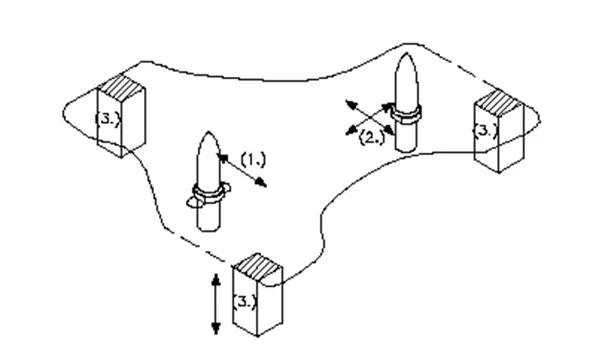
Figure 2.07
Body coordinate system
Body coordinate system on which BIW Geomentry is maintained and designed.
Figure 2.08 example Body Coordinate system
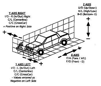
Figure 2.08
- The X axis points forward from the vehicle. (Front O Line)
- The Y axis points to the left, as viewed when facing forward (Center O Line) .
- The Z axis points up from the ground (Bottom O Line).
Reference axis system of the software is used for the design of the various features of the parts e.g. hole, fillet, threads, To correlate the position of all the automotive components during the final assembly the axis system of the vehicle is used. Most of the time vehicle axis system and software axis system is the same. The X-axis represents the length of the vehicle Y-axis represents the width of the vehicle Z-axis presents the height of the vehicle. Y-axis is considered to be located at the front axle. All BIW welding fixtures are designed with reference to the car line.
Let us consider a situation if individual fixture designer starts designing a part or panel on their default axes system then it will be difficult to assembly or position the part with respect to each other. So in order to avoid this all the designer starts designing with respect to car axes system.