Week 3:- BiW Fixture Design Methodologies Challenges
WWhat is Design Methodology?
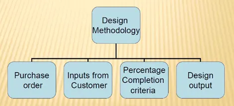
Design methodology is the steps we follow to do our concept designing stages of our fixture design. we need to consider some parameter to proceed with our design. There are 4 sub catagories for Design methodology are
1) Purchase order- This is confirmation from costomer side or green flag from customer side to proceed with our designing
2) Input from customer - These are the basic input from customers to designers so based on that input designers will make product
3) Percentage completion criteria - This is time schedule we create for completion of our design and from the completion of design we can calculate percentage
4) Design output - This consists for documents and CAD files which are the output of design and we will submit all the output to customer
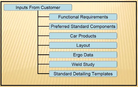
What are the inputs required from the customer to start designing a Fixture?
1) Functional Requirments: This gives the what are the fucntional requirements the Fixture design is goiing to have namely glueing, welding, fasteniing etc.
2) Preferred Standard Components: This is what are the standard components customer already have and our design must be made according to their standard components
3) Car product: It consists of all files such as 3D, 2D, and other documets in which we can learn and understand about geomentical tolerance and PLP or car product.
4) Layout : This consists of entire layout of out assembly unit it is easy to understand the worrkflow of unit
5) Ergo data: This gives the ergonomics data of manual operaters which links with fixture units
6) Weld Study: This is based on what type of weld we gonna do and which position of part are to be welded
7) standard Detailing Template: There are some standaed followed in certain comapny this template consists fo that standards in detail.
What is the input we get from "Car Products"?
The Inputs from car product are
1) Geomentric Dimension and Tolerance(GD&T) - gives all the dimenion and tolrance of the Part
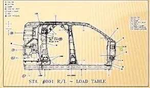
2) Part List - It consists for list of assembly of the part
3) CAD file or Part
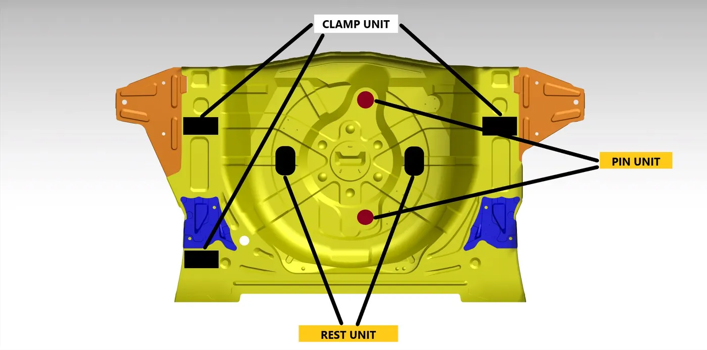
4) Clamp Plan - This gives where we gonna fix clamps or pins
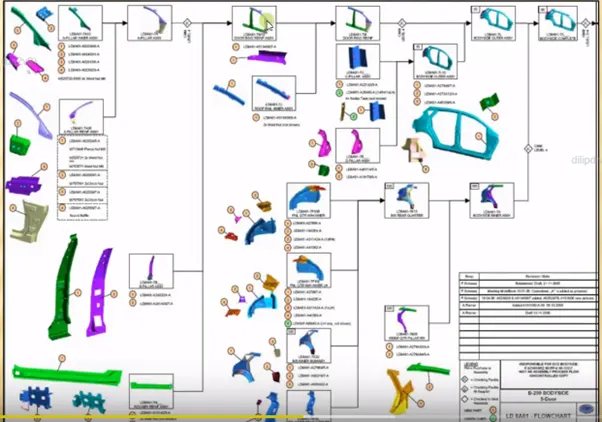
5) Product assembly Process Sheet
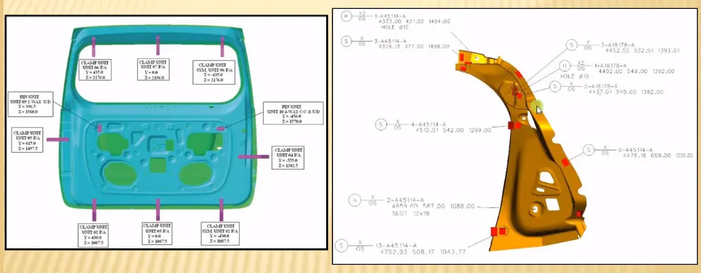
What is the Clamp plan?
This plan sheet gives you the excate coordinates where the parts are need to be clamped. Based on this sheet we will use clamps pins to hold the part and very important thing is we cannot change the clamp position if we need to change we need to confrim with customer and do it.
What is the purpose of a Layout?
This consists of entire layout of out assembly unit it is easy to understand the worrkflow of unit. It also gives the entire information of out work space from which we can undestand and figure how many robot are there and postions of other parts too.
What is Ergo data?
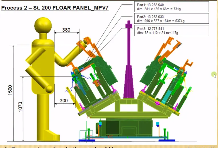
This gives the ergonomics data of manual operaters which links with fixture units. These data gives less error occurance and safety to opertators. From below image we can see the ergo data metioned for the fixture unit
What do you understand by Weld study?
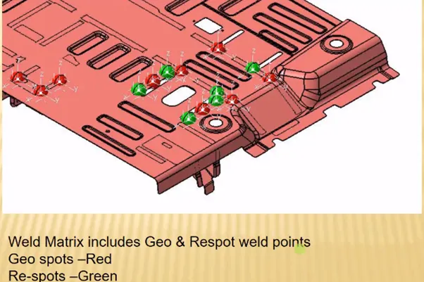
This study includes the study of weld gun, that is goning to be used while welding a fixture and which places are going to be welded. weld points are the points where welding is done. there are two type of points are geo weld point(red) and re spot point(Green). In geo weld point are the points welded in GEO tool and re spot point are points which are goinig to be welded in respot tool.
What are the criteria for percentage completion in the designing stage? Explain it in detail
There are totally four criteria of percentage completion
1) Input and concept design - 0 - 25% - Here concept design of the fixture will be built
2) Concept aprroval and simulation check - 25% - 40% - In this stage concept design will get approved and stimuation of the design will be done.
3) Design Freezing and Detailing - 40% - 85% - In this criteria deisgn will be finalized and detaling will be done.
4) Check and final dispatch - 85% - 100% - In this criteria final check will be done and product will be dispatched to coustermer.
Brief about "Output" in design?
Output design consists of all 2D and 3D deisgn documents and other IGS and step files. The output is classified into two types
Unitised Tool: It consist of two types of drawing key sheet and layout sheet. key sheet shows location of every unit and layout sheet indicates the detailed drawing of particular unit.
Non Unitised Tool: It doesnt has keysheet it give complete detalis in Layout sheet.
What do you understand by structuring a design tree? How does it reduce errors during the design process?
Struturing deisgn tree in catia improves the designer to with with different units easily. The naming of the each unit is followed in specific way so that it wont cause any problem. If all the naming is done well for all unit then all can be easily accesible and also editable which decrease time for designing and ocurance of less error.
What are Units? Mention 5 types of units.
Fixed Pin Unit: Consists of fixed pinned which cannot be moved
Retract pin Unit: Consists of the Pins which can be retracted back like up and down movement of certain distance
Rough Locator Unit: Used for loading and unloading of thr panel and components etc.
Rest Unit: This is unit which is used to rest the component with help of rest mylers.
Base Unit: It is the base were all the components will mounted over it.
Describe Fixed Pin units & their purpose?
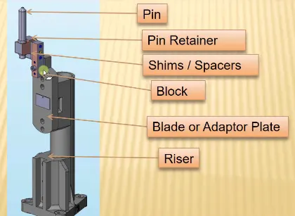
This is the unit which consists of fixed pin which is used to locate car panel and other components. If any component is fixed to the unit they all 6 DOF will get arrested for that component. Below mentioned are the parts of Fixed unit. So totally two directional shims is used to adjust the pi n position which can be fixed in panel or component.
What are the different parts of a fixed unit?
Riser : This the part which gives height to the assembly. Basically Risers will of L shape , frame type and square tube type.
Blade: Blades are called as adaptor plate in which other parts are get attached to it.
Block : Blocks are used to provide shimming adjustment. mostly they are in L shaped but they can be made in desired shape required for model
Shims : Shims are the tolarance spacers which is used for small adjustment of pins which is get fixed to the panel.
Pin retainer : Pin retainer is used to support , hold, rest the pins
Pins: It is the part which is going to fixed to the panel and locks the DOF of the panel there are two types of pin Round pin, diamond pin
What is the purpose of making a Rest unit & describe its parts?
This is the unit which is designed to support the car panel using Mylers
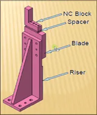
Riser : This the part which gives height to the assembly. Basically Risers will of L shape , frame type and square tube type.
Shims : Shims are the tolarance spacers which is used for small adjustment of mylers which rests panel.
Blade: Blades are called as adaptor plate in which other parts are get attached to it.
Mylers : This is part which wll rest or holds the panel or component.
What are the basic fundamentals to design a Sensor unit?
Sensor unit is sued to sense the car panel using electric signals and this signals is fedback to PLC then it will do next process.
Fundamentals to design a sensor unit:
1) The unit should be designes in a way as each panel which are beign welded should be sensed by sensor
2) If the panel size are larger then two sensors must be included in the design
3) The unit should be designes in a way as every sensor should be mounted in a 3 directional adjustment way.
What is a Rough locator unit & what are the basic fundamentals to consider while designing it?
It is the unit which is used to guide the operator to locate car panel onto the pins.
Basic fundamentals to consider while designing:
1) It should be placed at the edges of the car panel
2) It should guied the panle to pin arresting directrion
3) It should be designed with two slots for easy mounting
4) The slots should be in direction of car part guiding
5) It should be placed in same angle and from distance of 2-5mm from edge of car part.
What is a Base unit and describe it's parts?
From the name itself we can say that this is the base for all other units. This unit is used to mount all other units in it like rest unit, pin unit etc and also necessary parts like valve box and trunking cable will also be mounted over it.
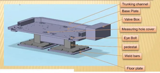
Base plate: This is the plate were all other units mounted over base unit and tickness of the place will be high to sustain all the units.
Floor plate: This the plate which is used to mount fixture on the floor
Pedestal: It is the support on which fixture is mounted
Eyebolt: It is the bolt which is used to move the fixture from one place to other using cables and ropes.
Measuring hole cover : This is the cover which is used to cover tooling holes
valve box: It consisits of solinoid values in it
Trunking channel: It is used to protect the inlet pressure in pneumatic device like cylinders etc
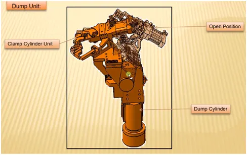
What is a Dump Unit and what are its functions?
It is the unit which is used when we have several constrain in unsing normal way then the panel with get attached in this unit. This unit has Dump cylinder for clamping car panel and its a complex unit
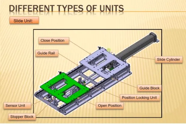
What is a Slide unit? Mention where Slide units are commonly used.
This unit is used when we have place constrains were we cannot use many units. parts of this unit are Guide rail, Guide block, Stopper unit, position locking unit and close, open position.