Week 3:- BiW Fixture Design Methodologies Challenges
1.DESIGN METHADOLOGY-
The design methadology is nothing but the steps followed during the concept design stage of fixtures design.
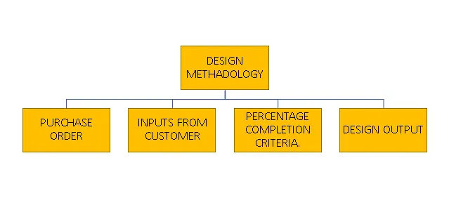
PRUCHASE ORDER
A purchase order (PO) is a commercial document and first official offer issued by a buyer to a seller, indicating types, quantities, and agreed prices for products or services. It is used to control the purchasing of products and services from external suppliers. Purchase orders can be an essential part of enterprise resource planning system orders.
INPUTS FROM CUSTOMER:
Each stage as the particular operation to be followed.in this design methodology stage.
PERCENTAGE COMPLETION CRITERIA-the amount of process is completed as per the given input is calculated & simulated & conforms it & sends to the next step.
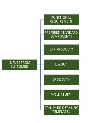
2.INPUTS REQUIRED FROM THE CUSTOMER TO START THE DESIGNING A FIXTURE.
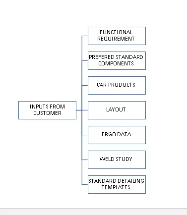
- FUNCTIONL REQUIREMENTS- the required opertaions to be done like welding,riveting,fastening etc.that information is given here to be followed in that particulr sequence to obtained the accurate product output.
- Weldimg fixtures-what type of welding to be used like stop or seam.
Hemming fixture
Checking fixture
Storage racks.
- PREFERRED STANDARD COMPONENTS- The design what is going to be done as per their previous data is already there with them because noone will attain to buy the same product that is already there .it will cost more. it save the time as well ass the cost also to reduse that the standard data is given as input which is to be design according to there components.
standards like ABB,NAAMS,DESTACO,ZYTRAN,TUNKERS.(tunkers are used in our biw em standards.)
standard parts like rizers,l blocks,retainers,pins.
components like clamps,cylinders,sliders,switches sensors.
weld guns tip dresses,tool changers.
- CAR PRODUCTS- the study of 3d & 2d data which is present with them like gd&t ,plp that car product has.(PLP) principle locating points.
- LAYOUT-The layout is the process of work tobe done in sequence to be followed to complete the work design.properly.
- ERGO DATA-It involves the required workers at the particular points to be done recieved as input its a standard data.
- WELD STUDY- it is a very imp input get's from the customer is like to do the operation welding, it requires the instruments like gun,gas,no of welds points, its position,coordinates etc, will get as input.
- STANDARD DETAILING TEMPLATE-Every company as their own standard it is like how to study the particular component to work on it in detail will be given as input by the customer.
3. INPUTS FROMCAR PRODUCTS-
- CAR PRODUCTS- the study of 3d & 2d data which is present with them like gd&t ,plp that car product has.(PLP) principle locating points.
- GD&T:geometric dimensioning tolerancing o the particular part.
- PART LIST: here what king of assembly is to be done & peerformed.
- CAD FILES OF CAR PART
- CLAMP PLAN
- PRODUCT ASSEMBLY PROCESS SHEET.
GD & T- provides he input of
- locating pins, rest,clamp,dumps & slide information of each station.
- sequence of opening of clamps dumps & slide stroke information.
PART LIST:
- here the part names &part no are mensioned in the table to make revision.
- tools revision.part thick what isthe thickness of the part.
- what type of gun used to design.
CAD FILES OF CAR PART: the file of the car part like 3d &2d models.
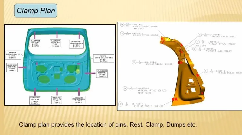
CLAMP PLAN:
It is a imp input that isused where the product to be placed the clapming units orthe pin units.
The position of the clamp should not be changed.it should be kept stable at that first position only (pin unit)
as per the given input.
we can change the desgn created by us but never has the permission to change the positon of the clamp input given by the customer it may faces the lot of errors.like it may damages the tool or the clamp while changing.
PRODUCT ASSEMBLY PROCESS.
There will be a product assembly process sheetin that sheet shows how the prduct assembly is to be processed from one assembly to the next stageas shown in the picture.
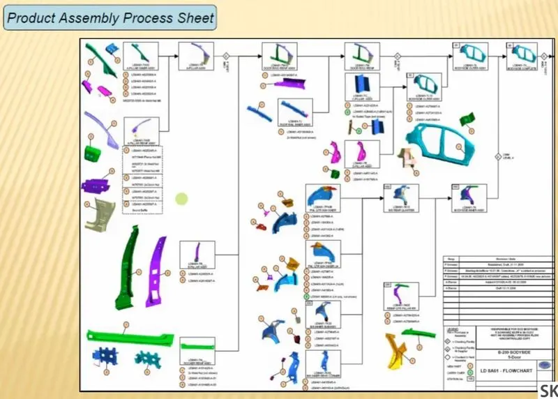
The process sheet shows the details information how to do & should follow it without any restrictions from starting till end (complete assembly.)
4.CLAMP PLAN:
It is a imp input that isused where the product to be placed the clapming units orthe pin units.
The position of the clamp should not be changed.it should be kept stable at that first position only (pin unit)
as per the given input.
we can change the desgn created by us but never has the permission to change the positon of the clamp input given by the customer it may faces the lot of errors.like it may damages the tool or the clamp while changing.
5.PURPOSE OF LAYOUT-
The purpose of layouts is to distribute the amount of space given to the view on which they are installed among the children of that view. Each subclass of Layout has a specific pattern of space distribution (a line, a 2D grid, etc.). See their documentation for details.
The layout sheet is the plan of arrangement of the robots, fixtures, assembly parts, jigs work space etc. on a specified area. so that the robots should have some rotational free space to move freely the robot will move about some distance from it position to do the operation like welding fixing, assembly etc. the robot reachable area is called as swept area of that robot.each robot has its own swept area.
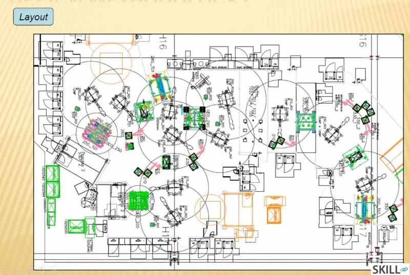
Layout provides information of
- Flow of parts
- Station pitch
- Robot stations
- Acessories like tool changer & tip dresser
- Sub assembly links
- Plat form height
- Loading unloading sequence /heights
FLOW OF PARTS: It is used to move the part from one station to the other station for doing the required operation
STATION PITCH:The distance b/w the two stations
ROBOT STATIONS:The position of the robot which is fixed at that particular position.
ACCESSORIES LIKE TOOL CHANGER & TIP DRESSER:
The required tool is changed accordingly as per the need by the movement of the robot The tip dresser is used to shapen the weld gun required.
SUB ASSEMBLY LINKS
PLAT FORM HEIGHT
LOADING UNLOADING SEQUENCE /HEIGHTS.
6.ERGO DATA:
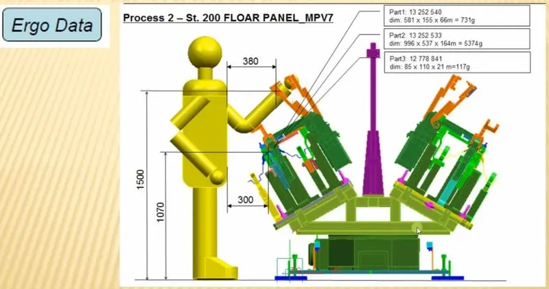
- Ergonomics refers to the study of humanbehaviour & movements
- Ergo dataprovides information of loading ,height ,working safety zone of operator etc.
- ergo data is given where the manual operation is required according to the height of the machine & distance b/w the machine & operator.
- It also provides the safety zone while the operation.
- this data has the information of the rues to be followed for the designing like the distance b/w the operator & machine height,etc. so that the operator sjould not feel risk while doing the work & it also effects his heath condtion,which is not good.
7.WELD STUDY:
WELD UN INCLUDES
weld gun details
weld matrix & weld points
Geo weld points
Respot weld points
A welding gun is a portable device used to achieve semi-automatic or automatic welds on pieces of metal. this gun is usd to join the two sheet metal parts to geather.weld study is used to study the positions of the weld points to be done & how many points tobe done & what king of is it. in detail.
these wed point will be done in 2 stations like geospot stations & respot welding .
which are pre planed station to be welded at that particular points.
8.PERCENTAGE COMPLETION CRITERIA:
Percentage completion criteria is followed in the designing stages & dispatch stages of the welding fixtures.
0-25% - Input & concept design
25-0% - Concept approval & simulation check
0-85% - Design freezing & detailing.
85-100% Check & final dispatch.
Percentage of completion (PoC) is an accounting method of work-in-progress evaluation, for recording long-term contracts. GAAP allows another method of revenue recognition for long-term construction contracts, the completed-contract method.The percentage of completion method falls in-line with IFRS 15, which indicates that revenue from performance obligations recognized over a period of time should be based on the percentage of completion. The method recognizes revenues and expenses in proportion to the completeness of the contracted project. It is commonly measured through the cost-to-cost method.
- 9.DESIGN OUTPUT:
- The output i 3d modes & the 2d drawings of the tools
- Utilized tools(multiple units on a common base) require two types of drawing sheets.
- key sheet - an index of unnits & their placements on the tool base.
- layout sheet -a detailed drawing of individual units rto include all their components
- Non -utilizedtools: tools that can stand alone & can be detailed compltly on a layout sheet.
A design output is a drawing or specification or manufacturing instruction. Design outputs describe all the components, parts, and pieces that go into your medical device. Design outputs describe all assemblies and subassemblies of your product.
- the output should compile following point;
- Approved standard components are to be used where ever possible.
- Design must be as simple & economical as possible.
- Design must complay with all current safety & ergonomic requirements
- Design must provide for controlled & damage free handling of product
- Adequate error proofing provision must be incorporated into each design by providing proximity switches,rough locators etc.
- The weight of the moving parts must be kept to a minimum while maintaining maximum strength.
- Frames & structures are to be simple & study.
- Design clearance & accessibilitry for routne maintanance & servie.
- Motion control must be considred on any moving equipments.
- Designer is responsible to validate clamps & all weld guns.
10 DESIGN TREE:
- Structuring a design tree implies to aprocess where all the assemblies & parts are named inaspecfic standard ,different customers hve diffrent set of standards t structure a design tree.
- It is an importsnt roces which helps isus to identify a specific part to assembly as to which project,tool or unit it= eblng to
- This helps us oavoid the errors during design study ,manufat=cturing ,assembly,inspection.
- If the parts or assemblies are not name properly ot the design tree uis not structires properly,it will create confusion to understand the design& may create major possibilities of making an error.
- Naming of fixture or a unit or apart ,gives the information as to which project or zone or assembly d do they belong.
- It can helps us to identify the quantity of items of same tye or different types that are being used in an assembly.
The main thing we have to do to over come with errors make sure the proper creation of the cmponents name & assembly name in the design itself. no error will come.
11.UNITS:
A unit is a evice that has a specified function,espically one forming of a comlex mechanism multiple units are joined togeather in order o form a ixture & are attached to a common base which serves as a common spport to this nits where they are fixed,
Awelding fixture is assembly of diff types of units
units are classified as
UNITISED TOOLS
1.UNITISED TOOLS:
unitised tools are basically tools which are a art of multiple tools inside of it.these are the tools which has to be represented by two formatsi,e. sheets & layout sheets ,unitized tools are basically two types.
- simple units
- simple unit will have a very simple design to it,that the apporach of the designing & manufacturing is also very simplistic ,simple units are classified as.
- REST UNIT :Rest unit is basically a unit where the component is tested there is no upper clampto it, no force applied to ot there is no cylinder attached to it usually it will have a riser a blade & few rest mylers.
- FIXED UNIT:fixed pin unit is basically aunit which has apin which is already fixed it cannot be removed.
- RETRACT PIN UNIT:Retract pin unit isoppsosite ti fixture which can be moved up& down by uing aetracablepneumatic cylinder ,so it can be retracted t a certain distance.
- ROUGH LOCATOR:A rough locator is a part designed to guide the operator to locate the car panel on the pins according a rough locartor can be of standard part or make part.
- SENSOR UNIT: A sensor units are used in actually sensing wheather the panel or a particular components is there or ot for example we will assemble the parts to ajoin to geather in the main ssembly component there will b emany of the parts which cant be rememer ass we are human , if we miss any part there will a loat of error in as cost time ,which will be effect to loss, thatthat why we provide semnsors to inform us.
- Baseunit: A base unit is a unit designed to mount all the other units.
b. COMPLEX UNITS:
- Complex units like slide unitis an example of a cmplex unit that design it self a lite complex in design aspect.
- SLIDE UNIT: the slide units are basically where the sliding mechaniss is involved.
- DUMPU UNIT: dunp unit is basically like a conveyor where we assemble a component id we have particular constraint.
NON UNITIZED TOOLS:
non unitized tools are basically one unit itself, which don't have any processes functionally to it is ajust to keep the component on it as a stable like grippers. trunk table,stands etc,nn unitized tools are
- Stands
- Take out trollys
- Conveyors
- Turn tables
- Some gripper.
12.FIXED PIN UNITS & THEIR PURPOSE.
It is designed to locate car panel using pins.it is already fixed & it can' move up & down.
- PIN
- PIN RETAINER
- SHIMS/SPACERS
- BLOCK
- BLADE/ADAPTOR PLATE.
The block is used to munt entire pin unit shimes are used to avoid stacku tlerance while ssembling entire components shims come in pack of 0.1,0.2 &0.5.
PURPOSE OF FIXED UNITS ARE
pin is most importsnt part of fixtures & used to restrict rotational as wel,as translational degrees of freedom of that particluar component purpose of fixed pin unit is to fix tht panel stanle f not it may cause many errors.motion along tw axis & to prevent rotational of panel in the axis of panel.
13.FIXED UNITS types:
- locating pin
- pin retainer
- shims
- blade
- riser.
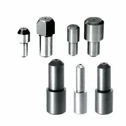
locating pin:Typically, locating pins are used for controlled, fine tolerance positioning of a work piece. For example, a pallet that is moved along one axis, where the drive mechanism is not accurate and stable enough to place it in a position sufficiently accurate to execute a particular process, the use of locating pins may be the best solution.
RISERS: Riser isa structre generallu used to mount the toggle clamp & rest ,clamp mylars & location pin.
it is not necessary to have one riser where all the parts of clamp or rest location units are mounted.
these are designed & manufactured to give height to the assembly.
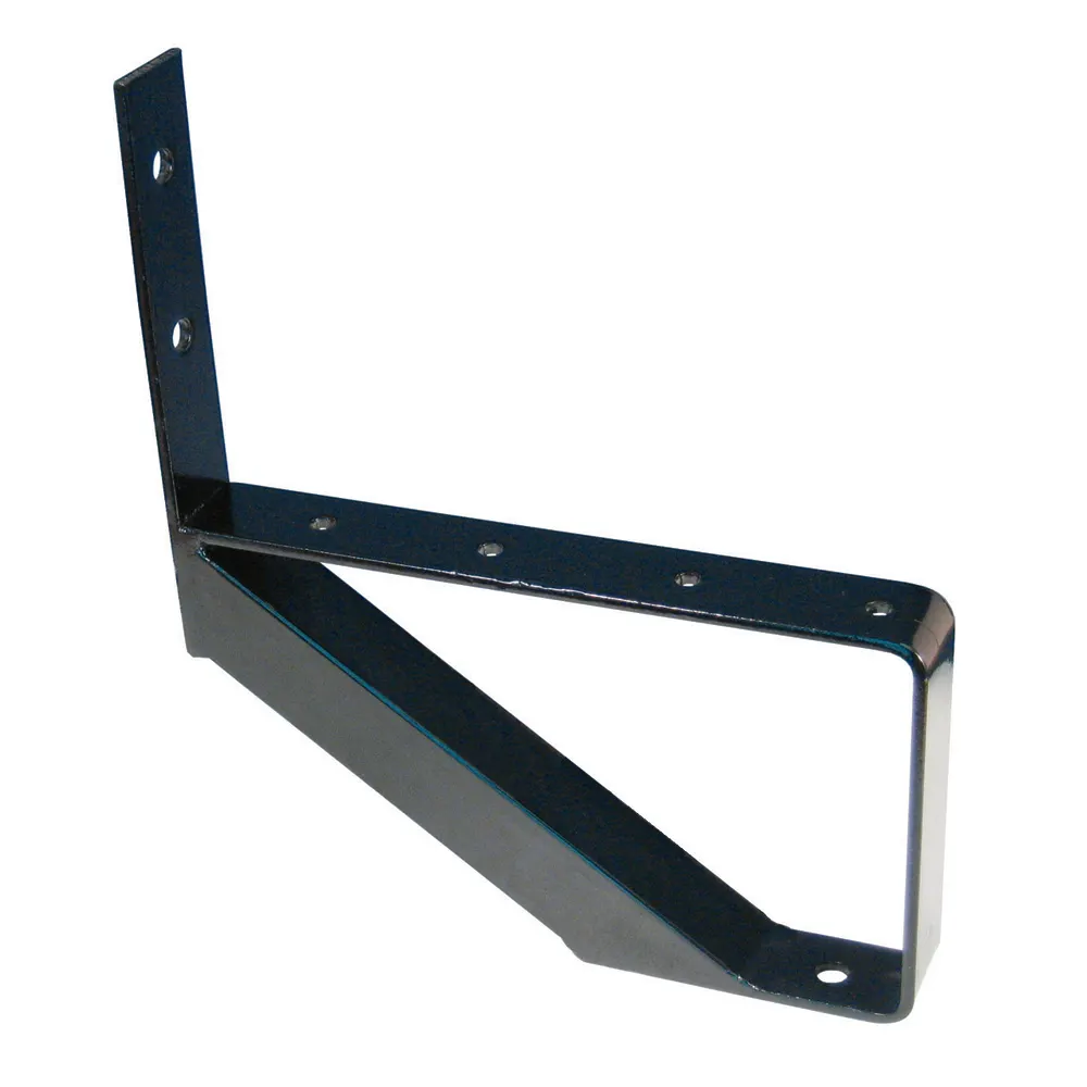
BLADE:Blade are the plates attached t the riser .parts like cylinder,arms etc, are monted on the blad,chamfer is given to straight the blade.
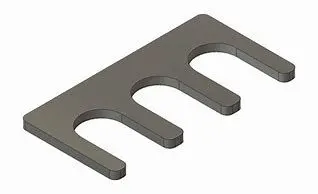
SHIMS:metal shims are used t finely adjust the location of how the fixture holds the product so that it welded togeather within the dimensions set for the product to work well.
A pack of thin metal shims is placed b/w the two components in the fixture the first component is fixed in place & the second component is attched to the first component with the pack of shims in b/w removing one shim or adding one shim slightly adjusts the location of the second compnent This is imprtsnt to manufacture who ant to their products parts assembly easily after beng weded.
PIN RETAINERS:
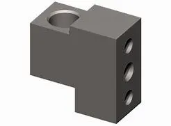
A pin retaier is a part which holds the pn in position ,the pin retainer can be either a make part or a standard part also .pin retainer is used to hold the locating pins.
14.PURPOSE OF MAKING A REST UNIT: Rest unit is unit designed to support car panel using ,yler/NC book rest component is rested only no upper clamp r force applied there it is the simplest unit to designbecause it has some parts to design & the puspose is only resting of the car panel.
it can be combined with the clap unit as well as to rest the car panel. also locating clamping, &test unit can be combned together in one unit to reduce cost.
There is no cylinder attched to it. has rest myler blade & riser & below is diff parts of the rest unit.rest unit is also divided into simple support unit multiple support units & retractable support unit.'
types of rest units
- NC blocks/mylor
- Spacers
- blade
- riser
15.BASIC FUNDAMENTALS TO DESIGN A SENSOR UNIT:
NC block/mylors
MYLAR is one kind of block that touches the panel and holds or clamps the panel. Mylars are always designed in CAR LINE. Mylar is also called NC(Numerically Controlled)Block. Mylars are mounted on
any block or plate with Shimming, So that height of mylar can be adjusted accordingly at the assembly level
RISERS: Riser isa structre generallu used to mount the toggle clamp & rest ,clamp mylars & location pin.
it is not necessary to have one riser where all the parts of clamp or rest location units are mounted.
these are designed & manufactured to give height to the assembly.
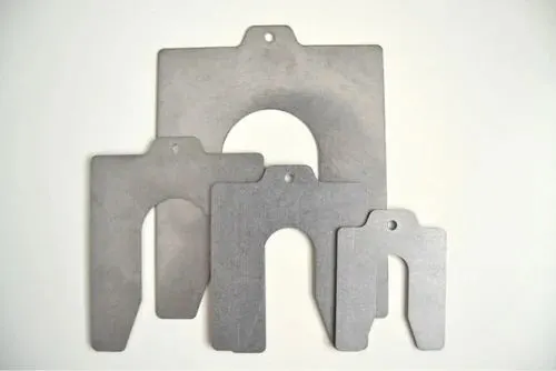
SHIM:
- Vision and Imaging Sensors
- Temperature Sensors
- Radiation Sensors
- Proximity Sensors
- Pressure Sensors
- Position Sensors
- Photoelectric Sensors
- Particle Sensors
- Motion Sensors
- Metal Sensors
- Level Sensors
- Leak Sensors
- Humidity Sensors
- Gas and Chemical Sensors
- Force Sensors
- Flow Sensors
- Flaw Sensors
- Flame Sensors
- Electrical Sensors
- Contact Sensors
- Non-Contact Sensors
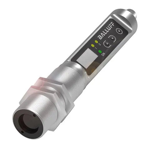
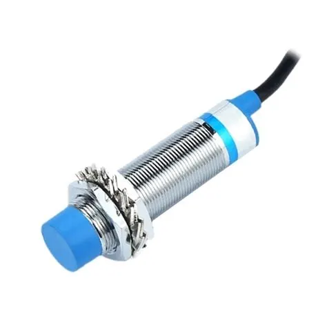
Proximity Sensors
Proximity Sensors are electronic devices used to detect the presence of nearby objects through non-contacting means. A proximity sensor can detect the presence of objects usually within a range of up to several millimeters, and, doing so, produce a usually dc output signal to a controller. Proximity sensors are used in countless manufacturing operations to detect the presence of parts and machine components. Key specifications include sensor type, maximum sensing distance, minimum & maximum operating temperatures, along with dimensions of diameter and length. Proximity sensors are generally short-range devices but are available too in designs that can detect objects up to several inches away. One commonly used type of proximity sensor is known as a capacitive proximity sensor. This device uses the change in capacitance resulting from a reduction in the separation distance between the plates of a capacitor, one plate of which is attached to the object being observed, as a means of determining motion and position of the object from the sensor.
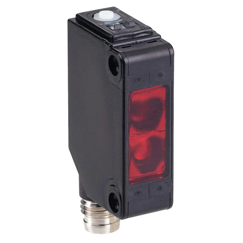
Photoelectric Sensors:
A photoelectric sensor is a device used to determine the distance, absence, or presence of an object by using a light transmitter, often infrared, and a photoelectric receiver. They are largely used in industrial manufacturing. There are three different useful types: opposed (through-beam), retro-reflective, and proximity-sensing (diffused)
 .
.
LASERSENSORS:
Laser sensors are used where small objects or precise positions are to be detected. They are designed as through-beam sensors, retro-reflective sensors or diffuse reflection sensors. Laser light consists of light waves of the same wave length with a fixed phase ratio (coherence)
FUNDAMENTSLS OF SENSOR DESIGN:
every single loose panel,which are being welded in a tools should be sensed.
Each panel should be sensed by one or two sensors depending on the size of the panel prefered to be in diagonally opposite ends of the panel.
If a component is really small,we need not use two or three sensrs for that you can use one sensors to detect the particular panel.
If the panel is really big we will use two sensors in opposite directions to sense the panel.
So every sensor should be mounted in three directonal adjustable ways in general.
Sensor manufacturing are IFM ,peperl, fuchs ,OMRON etc.
16.ROUGH LOCATORS & ITS FUNDAMENTALS:
rough locators are elements thataid the operator guide the car panels while loading onto the fixtue & ensure of fool-proof assembly
FUNDAMENTSALS OF ROUGH LOCATORS:
- Rough locators should be placed at the edges of the car panel which it has to guide.
- Rough locators has to be place at the same angle of the acr part edge with a minimum distance of 2.5 mm from the edge of the car part.
- Rough locators shuld be guided the panel in the pin arresting direction.
- Rough locators should guide the panel bbefore 10-15 mm to start of the pin engage ment.
- Rough locators should be designed with entry angle for the car panel generally it ranges b/m 30-5 deg.
- The locators should be in the direction of car part guiding.
17.BASE UNIT & ITS PARTS.
A base unit is the unit designed to mount all the other units (clamp unit,pin,unit, rest unit etc.) of the tool ,also other parts necessary for tool pneumatic vaue box,trunking cable,pat will also be mounted onto a base unit.
parts of base unit.
- valve box
- Trunking channel
- Measuring hole cover.
- Eye bolt
- Pedestal.
- Foor plates.
Value box which supplies air toall pneumatic ctlinders assembled in the fixture.value box consists of one solenod vaue isused to collect the air from the pneumatic cylinders to value box.
Trunking channel:Trunking channel is a kind of cable duct,which helps to guide & protect the wirings /tubes used in the fixtures.
Meauring hole cover.In the measuring hole cover the coordinates points are engraved n it.
The hole which mention the coordinates gives the position placements of the particular unit.
The measuring hole helps in CMM inspection & QC inspection.
Eye bolt: An eye blt is a bolt with a lop at one end, they are used to firmly attch a securing wye to astructure so that ropes of cables may then be tied to it for lifting purpose.
Eye bolt is used to frag ot lift the base unit while relocating.
PEDESTAL: Pedestal is a stand like structure where the entire unit of the base will be mounted.
Floor plates:Floor plates is used to mount the entire base with the floor Also helps to achive the flatness of the fixture Hence the base unit & their parts are explained in detail.
18.DUMP UNIT: Dump unit is where you assemble compnent if you have certain constraint here you will have clamp unit pin unt attached panel will be assembled so if you have certain constraints you cannot assemble in normal way dump unit use in diff way.it has dum cylinders& complex design it consists dump cylinders to perform the operation of clamping & unclamping car panel. a dump unit can have more than one cylinder toperform such operations the first cylinder dumps the assembly carrying the clamp .mylo=ar pins & them this assembly performs the reqired operation n this unit. we should mae sure that in the open position of panel we should be able to remove the panel.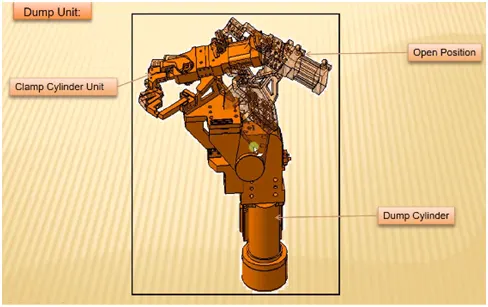
FUNCTIONS OF DUMP UNIT:
if e have a prticular constraint & we can't assemble in a normal way to use this it in diff ways again it has same dump cylindr & it has open position & closed position & it has clamp cylinder unit to.
if we have aby geomentrical consraints can use this dampener to constrain the components.
19.SLIDE UNITS & WHERE HE SLIDE UNITS ARE USED COMMONLY.
Slide units: slide units are positioning units which are used topositio the car part or panel units weld gun, robots for the further perations.
Slide units may be classified into two types based on the types of guide ways. they are
Hardened guide ways.
LM guide way.
Slide units may further classified in to theree types based on the prime mover they are.
Manual slides
Hydraulic/pneumaticslides
CNC slides.
It may be further classified depending on the application as
Horizontal slide unit
Vertical slide unit
Angular slide unit.
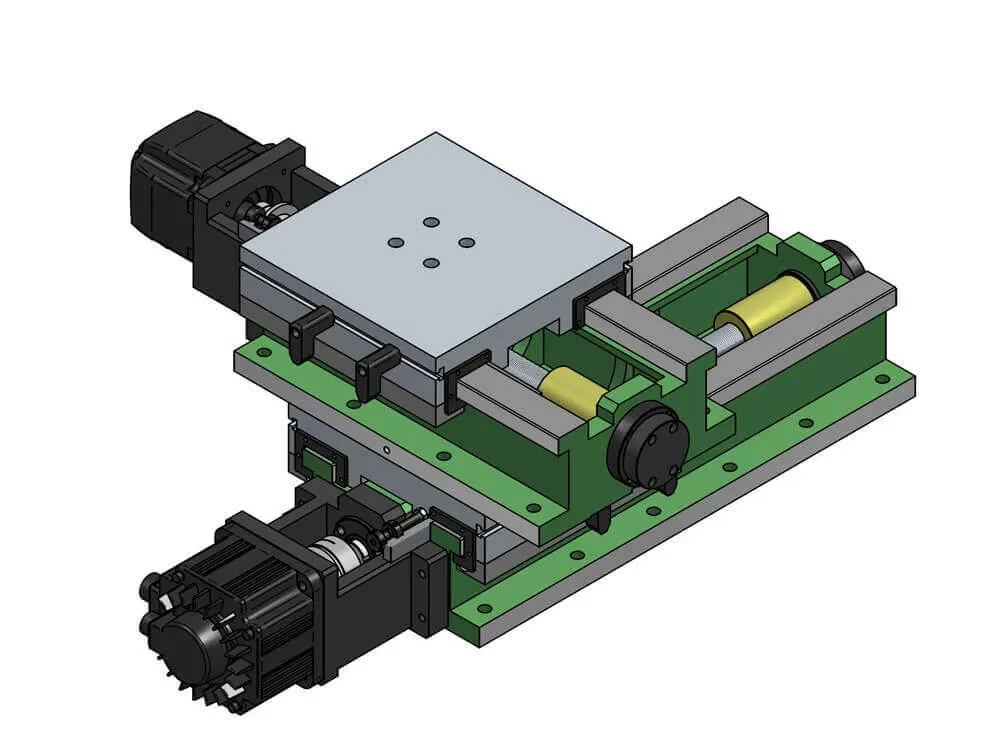
Linear slides, also referred to as linear guides or linear-motion bearings, are types of bearings that allow smooth and near-frictionless motion in a single axis. Machine tools, robots, actuators, sensors, and other mechanical equipment often require moving components in a straight line in any of the three-dimensional axes. Free translational motion while being in contact with another object is countered by friction. Friction is the force exerted by two bodies against each other which are always against the direction of motion. The amount of frictional force exerted is governed by the load acting on the surface in contact and the surface property known as the coefficient of friction.