Week 3:- BiW Fixture Design Methodologies Challenges
INTRODUCTION TO BIW FIXTURE DESIGN METHODOLOGIES
OBJECTIVES: The main objective of this challenge is to understands the theory related to BIW fixtures design and how it,s designed using softwares and to answers questions that are asked in the challenge and to preparea detailed report fot the same.
1. DESIGN METHODOLODY: Design Methodology is nothing but the steps followed during the concept designing stages of fixture design.
The design methodolody is divided into four sub categories, they are mentioned in the below steps,
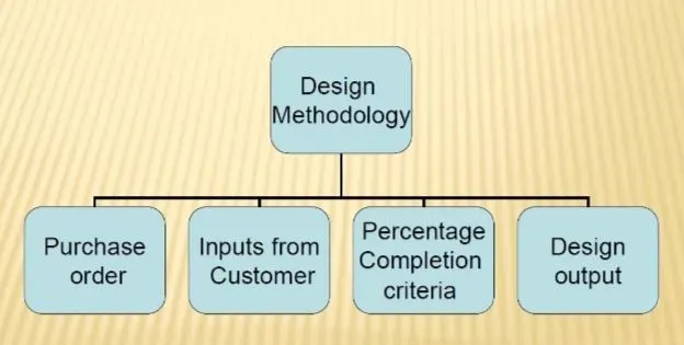
DESIGN METHODOLOGIES:- 1. Purchase order
2. Inputs From Customer
3. Percentage Completion Criteria
4. Design Output.
PURCHASE ORDER: Purchase order is the start of the work, it is the confirmation of order from the customer. The customer confirms the order once we have submitted our design concept. Once he given the purchase order then we will start working. Purchase order is also called as letter of intent.
INPUTS FROM CUSTOMER: In this customer describes his requirments and specification what he needs to be included in the desig of fixture. The specifications are like functional rquirements, space available, layout etc.,
PERCENTAGE COMPLETION CRITERIA: Percentage completion criteria is followed in the designing stages and dispatch stages of the welding fixtures.
DESIGN OUTPUT: The design output is the 3D desig output and the 2D drawings what we get from the design software.
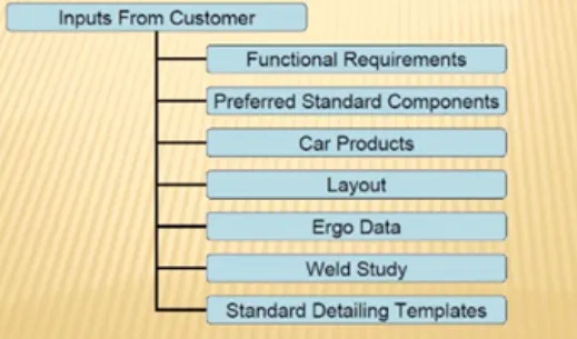
2. Inputs required from the customer to start designing a Fixture: The inputs which are required from the custmer side to start designing a fixture are given below,
- Functional Requirements
- Preferred Standard Components
- Car Products
- Layout
- Ergo Data
- Weld Study
- Standard Detailing Templates.
These inputs will help us and ease our efforts in designing the components and also saves time for us.
FUNCTIONAL REQUIREMENTS: The informations that we get from functional requirements are as listed below,
- Welding fixtures
- Hemming fixtures
- Checking fixtures
- Storage racks.
These requirement helps in to describe the function of the fixture i.e for which purpose we are using the fixture is what we can get from this requirement.
PREFERRRED STANDARD COMPONENTS: Different companies follow different different stadards, so our customer follows one or two standards in order to detail the product completely, The examples of standards are given elow,
- Standards like ABB, NAAMS, DESTACO, ZYTRAN, TUNKERS.
- Standard parts like Risers, L-Blocks, Retainers, Pins
- Components like Clamps, Cylinders, Slides, Switches, Sensors
- Weld guns, Tip Dressers, Tool changers.
CAR PRODUCTS: Car products include,
- GD&T
- Part list
- Cad Files of car part
- Clamp plan
- product assembly process sheet
LAYOUT: Layout provides information about
- flow of parts
- station pitch
- robot stations
- accessories like tool changer and tip dresser
- sub assembly links
- platform height
- Loading/ Unloading Sequence/heights.
ERGO DATA: Ergonomics is the process of designing or arranging workplaces, products and systems so that they fit the people who use them. Ergonomics aims to improve workspaces and environments to minimise risk of injury or harm.
WELD STUDY: Weld study includes
- Weld Matrix & Weld points such as Geo weld points and Re-spot weld points.
- Weld gun details.
3. INPUTS WE GET FROM CAR PRODUCTS :
Car products include,
- GD&T
- Part list
- Cad Files of car part
- Clamp plan
- product assembly process sheet.
GD & T : GD & T stands for geomentric dimensioning and tolerance which gives the geomentric dimenssions of the parts and tolerance which we have to use for the holes and other parts.
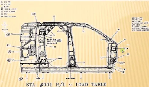
GD & T provides information of,
- Locating pins, Rest clamp, Dumps & Slide information each station.
- Sequence of opening of clamps, dumps & Slide stroke information.
PART LIST: Parts list , also known as a bill of materials (BOM) is a tabular list of the items used to make an assembly. Parts list is usually combined with the assembly drawing, but it is a separate and individual document and can be and provides a complete list of all parts needed to build the complete project.
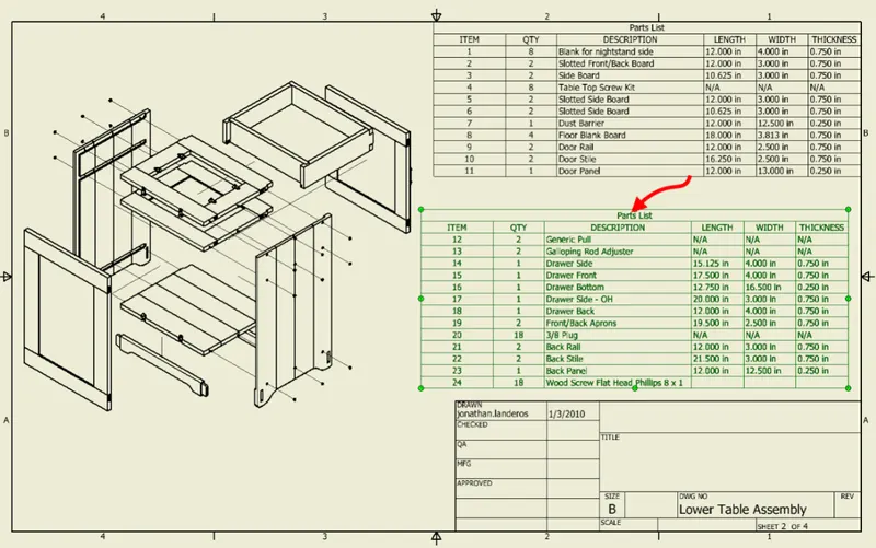
CAD FILES OF CAR PARTS: The cad files include 3d part files and 2d drawings which are required for the design. The cad files may include class A surfaces of the parts.
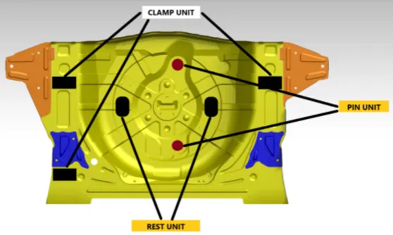
CLAMP PLAN: Clamp plan provides the informtion of location of pins, Rest units, clamp unit, Dumps etc. It is the important input from customer. The clamp plan/position should not be changed without the knowledge of customers.
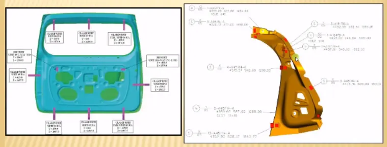
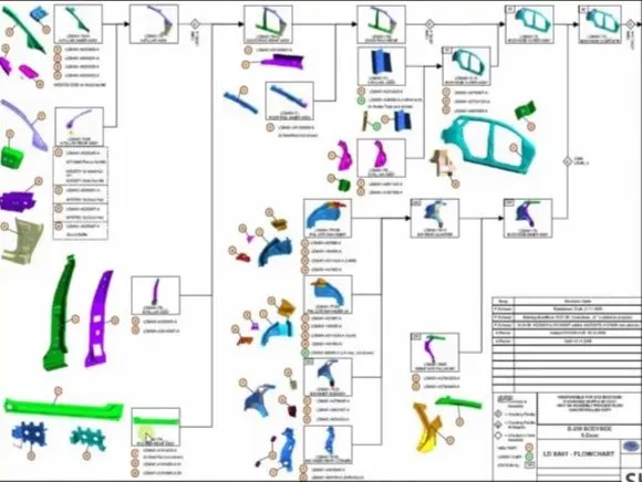
PRODUCT ASSEMBLY PROCESS SHEET: The product assembly process sheet shows how the products are going to move from one assembly to another assembly. The prodcut assembly process sheet also gives a detailed information or plan about how the components are welded.
4. CLAMP PLAN: Clamp plan provides the informtion of location of pins, Rest units, clamp unit, Dumps etc. It is the important input from customer. The clamp plan/position should not be changed without the knowledge of customers.
5. PURPOSE OF LAYOUT:
Layout planning is deciding on the best physical arrangement of all resources that consume space within a facility. These resources might include a desk, a work center, a cabinet, a person, an entire office, or even a department.
Decisions about the arrangement of resources in a business are not made only when a new facility is being designed; they are made any time there is a change in the arrangement of resources, such as a new worker being added, a machine being moved, or a change in procedure being implemented. Also, layout planning is performed any time there is an expansion in the facility or a space reduction.
The arrangement of resources in a facility can significantly affect the productivity of a business. A lot of wasted time, energy, and confusion can result from a poor layout. There are also other reasons layout planning is important. In many work environments, such as office settings, face-to-face interaction between workers is important. Proper layout planning can be critical in building good working relationships, increasing the flow of information, and improving communication. Similarly, in retail.
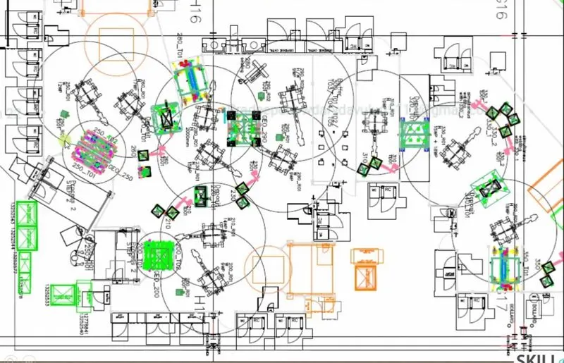
Layout provides information about
- flow of parts
- station pitch
- robot stations
- accessories like tool changer and tip dresser
- sub assembly links
- platform height
- Loading/ Unloading Sequence/heights.
6. ERGO DATA AND IT'S IMPORTANCE:
In ergonomics, the worker is the central figure. That means fitting the job to the worker’s capabilities. Ergonomics is NOT implementing the latest stretching program (although that may play a role in decreasing injuries), but it IS about looking at the tasks that are being performed and matching them with the capabilities of the worker to minimize injury risk and maximize quality and efficiency.
BENEFITS OF EFFECTIVE ERGONOMICS:
- Improved saftey of the operator or manufacturer.
- Workers health.
- Improved productivity.
- Improvement in the quality of the product
- Decreases the cost of the product, so that the profit will increase automatically.
- A better workforce can be achieved by efffective ergonomics.
Ergo data provides information of loading hieght, working saftey zone of operator etc.,
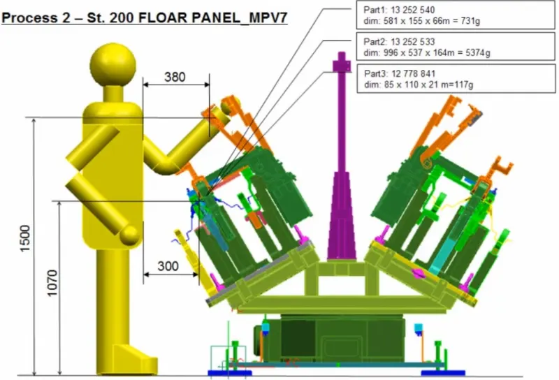
7 . WELD STUDY : Weld study is a study which involves the study of weld guns, the weld study includes
- Weld Matrix & Weld points such as Geo weld points and Re-spot weld points.
- Weld gun details.
Weld point is a point or coordinates where the welding is going to happen. The below image shows the weld matrix and weld points
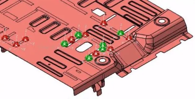
In general the data of weld points is given in the form of sphere's. The point's which are in red colour are geo spots and the sphere's which are in green colour are re-spot weld points.
8. CRITERIA FOR PERCENTAGE COMPLETION IN DESIGN STAGE:
Percentage completion criteria is followed in the designing stages and dispatch stages of the welding fixtures.
- 0 - 25% - INPUT AND CONCEPT DESIGN
- 25 - 40 % - CONCEPT APPROVAL AND SIMULATIONS CHECK
- 40 - 85 % - DESIGN FREEZING AND DETAILING
- 85 - 100 % - CHECK AND FINAL DISPATCH.
The main purpose of this percentage completion is to know how much the project has been completed and to know weather we are lying with the planned shedule or not.
9. OUT PUT IN DESGN :
The output of any design that we do is in the form of 3D models or 2D drawings of the tools or parts. Here we have two types of tools, they are
- UNITIZED TOOLS : These are multiple units on a coomon base and they require two types of drawing sheets and they are given below
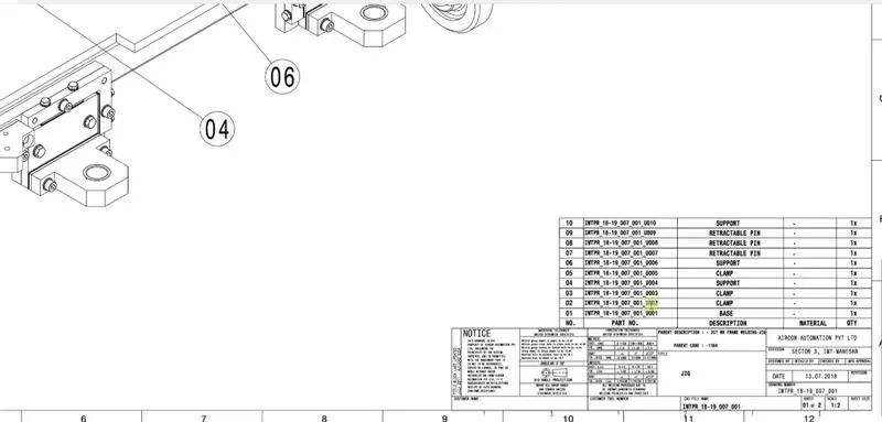
Key sheet : Key sheet is an index of units and their placements on the tool base.
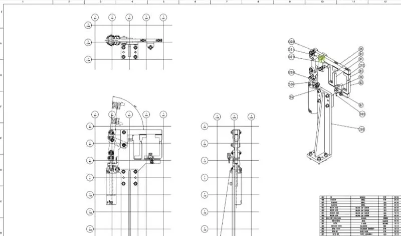
Layout Sheets: A detailed drawing of the individual units to include all of their components
- NON- UNITIZED TOOLS: Tools that can stand alone and can be detailed completely on a layout sheet.
An image of key sheet has been given in the below figure,
An image of layout sheet has been given in the below image,
The output should compile the following point:
- Approved standard components are to be used wherever possible
- Design must be simple and economical as possible
- Design must comply with all current saftey and ergonomics requirements
- Design must provide for controlled and damage free handling of product
- Adequate error proofing provision must be incorporated into each design by providing proximity switches, rough locators etc.,
- The weight of the moving parts must be kept to a minimum while maintaining maximum strength
- Frames and sructures are to be simple and study
- Design clearance and accessibality for routine maintanance and service
- Motion control must be considered on any moving equipments
- Designer is responsible to validate clamps and all weld guns.
10. STRUCTURING OF DESIGN TREE AND IT'S IMPORTANCE:
- Structuring a design tree implies to a process where all the assemblies & parts are named in a specific stndard. Different customers have different set of standards to structure a design tree.
- It is an important process which helps us to identify a specific part or assembly, as to which project, tool, unit, it belongs to.
- This helps us to avoid errors during design study, manufacturing, assembly, inspection etc.,
- If the parts or assemblies are not named properly or the design tree is not structured properly, it will create confusion to understand the design & may create major possibilitiesof making an error.
- Naming of a fixture or a unit or a part, gives the information as to which project or zone or assembly do they belong.
- It can help us to identify the quantity of items of same items of same type or different types that are being used in an assembly.
If we proceed further in the design without proper tree structure in the later stages of design it will create confussion and may lead to errors, so that maintaining a proper tree structure is necessary in designing a complex units like fixtures.
11. UNITS AND ITS TYPES :
A unit is nothing but a assembly is a assembly which has some special purpose or fucntion to do such as clamping, holding the panel, locating and resting etc.,
Different types of units are,
- FIXED PIN UNIT: Fixed pin unit is a unit designed to located the car panel using pins.
- RETRACTABLE PIN UNIT : A retractable pin unit designed to locate the car panel using pins, but the entire pin package parts will be mounted on the retractable pneumatic cylinder.
- REST UNIT : A rest unit is a unit designed to rest / support the car panel using NC blocks/ Mylar / Rest.
- CLAMP UNIT : A clamp unit is a unit designed to clamp / hold the car panel with NC blocks / Mylar / Rest by using a pneumatic cylinder.
- SENSOR UNIT : A sensor unit is a unit designed to sense the car panel by using electrical sensors. This signal from the sensors will be fed to the PLC and so the next process will be executed by this signal.
12. FIXED PIN UNIT AND ITS PURPOSE:
Fixed pin unit is a unit designed to located the car panel using pins. The image of a fixed pin unit is as shown in below figure,
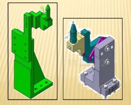
The purpose of fixed pin unit is to restrict the motion of the panel in respective direction and rotation of car panel in respective axis. The another purpose of fixed pins is to locate the car panel exactly by using pins.
13. DIFFERENT PARTS OF FIXED PIN UNIT:
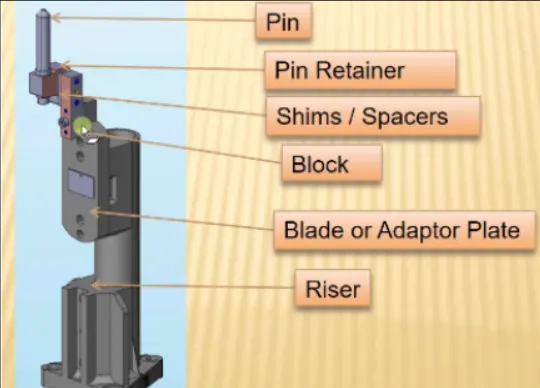
The various parts of fixed pin unit are
- PIN
- PIN RETAINER
- SHIMS/ SPACERS
- BLOCK
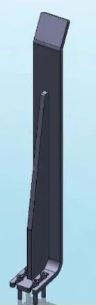
- BLADE OR ADAPTOR PLATE
- RISER
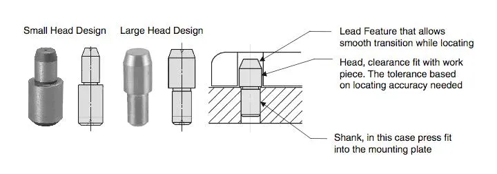
PIN: locating pins are used for controlled, fine tolerance positioning of a work piece. For example, a pallet that is moved along one axis, where the drive mechanism is not accurate and stable enough to place it in a position sufficiently accurate to execute a particular process, the use of locating pins may be the best solution.
Usually two locating pins are enough to properly locate the work piece on one plane.
There are dozens of styles of locating pins that can be utilized in a design. We will explain the structure and show an example of how each style can be applied.
One of the most common pins is a stepped pin with either small or large head.

- NC BLOCK
- SPACER
- BLADE
- RISER
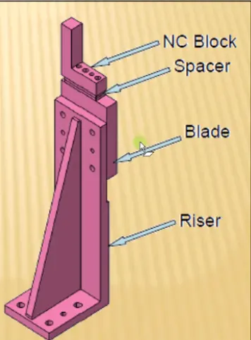
MYLAR is one kind of block that touches the panel and holds or clamps the panel. Mylars are always designed in CAR LINE. Mylar is also called NC(Numerically Controlled)Block. Mylars are mounted on any block or plate with Shimming, So that height of mylar can be adjusted accordingly at the assembly level. For ‘A’ class surfaces Nylon mylars are used. So that surface can be saved from scratches.
Shimming can be 1 directional, 2 directional, or 3 directional as per the NC cut.
- Every single loose panel which are being welded in a tool should be sensed.
- Each panel should be sensed by 1 or 2 sensors depend on the size of panel, preferred to be in diagonal opposite ends of the panel.
- Every sensor should be mounted in a 3 direction adjustable way in general.
Some major sensor manufacturers are IFM, Pepperl-fuchs, SICK, OMRON etc.,
Types of sensors used in general are;
- Proximity sensors
- LASER Sensors
- Photo electric sensors.
16. ROUGH LOCATOR & FUNDAMENTALS TO DESIGN IT:
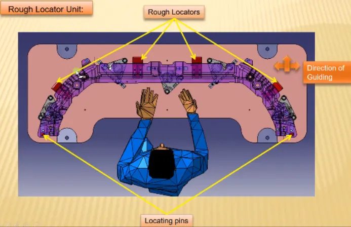
A rough locator is a part designed to guide the operator, to locate the car panel on to the pins accordingly. A rough locator can be of standard part or make part.
FUNDAMENTALS OF ROUGH LOCATOR DESIGN :
- Rough locator should be placed at the edges of the car panel, which it has to guide.
- Rough locators has to be placed in the same angle of the car part edge with a minimum distance of 2-5 mm from the edge of the car part.
- Rough locaators should guide the panel in pin arresting direction.
- Rough locators should start guiding the panel before 10 to 15 mm to the start of the pin engagement.
- Rough locators should be designed with entry angle for car part entry.
- Rough locators should be designed with two slots to mount for easy adjustaments.
- The slots should be in the direction of car part guiding.
17. BASE UNIT AND ITS PARTS :
A base unit is the unit designed to mount all the other units such as clamp unit, pin unit, rest unit etc., of the tool, also other parts necessary for a tool like pneumatic valve box, trunking cable path will also be mounted on to a base unit.
A base unit and its parts are given in the below image:
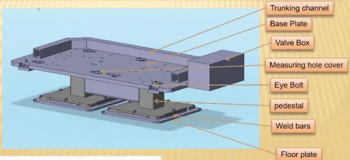
TRUNKING CHANNEL: Trunking Channel is a duct that carries all the electrical and pneumatic connections(wires and pipes) for units of the tool.
BASE PLATE : Base Plate is a machined plate made of steel or Aluminium of thickness 25mm to 40mm on which the holes are drilled to mount diffrent units like rest units, clamp units, pin units etc. Pedestal:Pedestal is a part or an assembly (welded structure) that joins the base plate to the oor plate.
VALVE BOX : A valve box is a device which supplies air to pneumatic cylinders and coils for the proper actuation of fixture parts.
MEASURING HOLE COVER : These are used to specify the exact position of the clamping unit or any other units in the for of co orf=dinates.
EYE BOLT: Eye bolts are used to lift the entire base securely and to fix the base firmly.
PEDESTAL : Pedestal is a part or an assembly (welded structure) that joins the base plate to the oor plate. Pedestal can be a standard part or a make part, depending on size and height of fixture Depending on the size of base plate,the number of pedestal for a fixture can vary for load distribution.
FLOOR PLATE : Floor Plates is grouted to the floor with xed bolt on the ground. Floor plates are also called foundation plates. There is a clearance of 10mm between pedestal base plate and oor plate. This gap is used to level the entire tool using leveling bolts. Weld bars are used to position the positions permanently.
18. DUMP UNIT AND ITS FUNCTION :
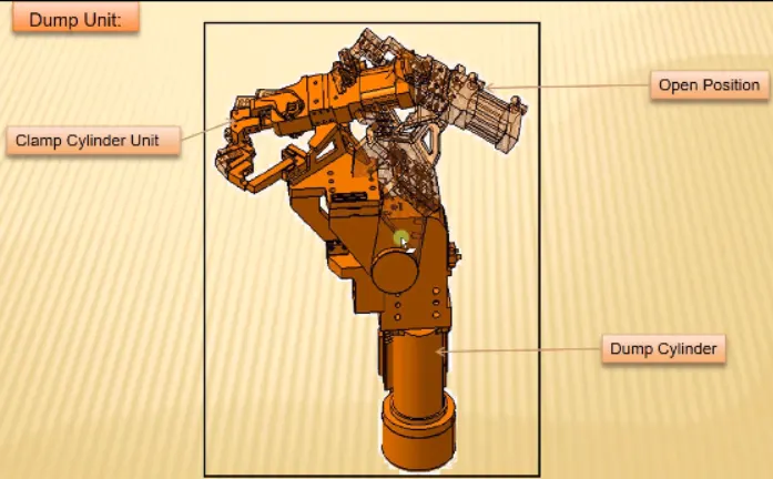
A dump unit is a unit where actually you can assemble a component if you have certain constraints which cannot be assembled in a normal way.
19. SLIDING UNIT:
A sliding unit is a unit which consists of a sliding cylinder which has guide rails to move the unit.
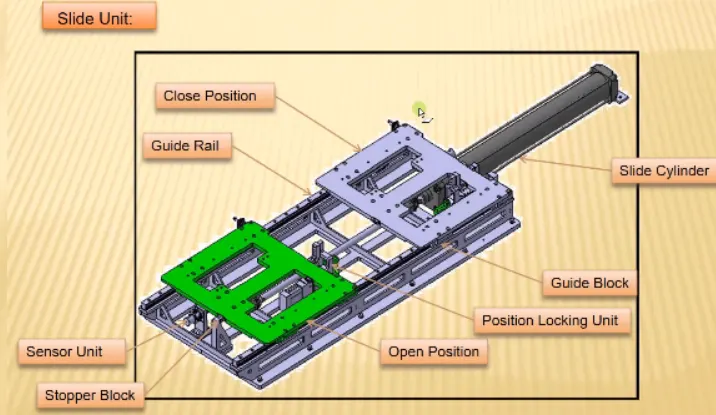
In general these sliding units are used where the space availabel is very less and it is not possible to use any other units.
CONCLUSSION
And hence we are concluding that a detailed report has been prepared to the questions asked in the challenge and images have been attached where ever and whenever required and possible.