Week 3:- BiW Fixture Design Methodologies Challenges
1) What is Design Methodology?
Design methodology states the method or process or steps to be followed while doing a design. Design methodology includes design tree in which the name the particular component or particular assembly, or the part of an assembly will be shown in particular order which will be easily understandable by anyone.
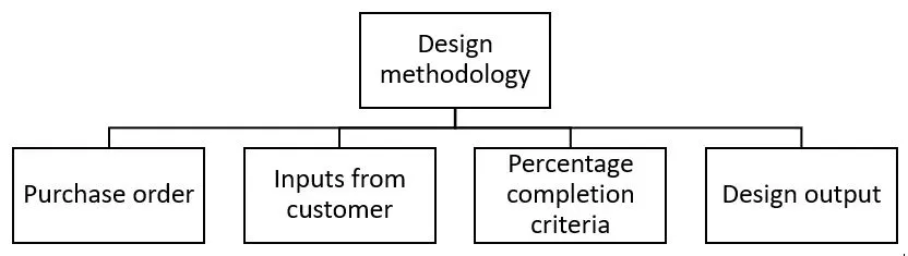
Image 1.0 : Design methodology and steps involved in it
1)Purchase Order
It is basically a confirmation from the customer side, that we are ready to start the designing.
2)Inputs from Customer
Input from customers are the major inputs/suggestions that we receive from the customers, These inputs we have to study and analyze those inputs.
3)Percentage Completion Criteria
Percentage completion criteria is a time plan / schedule which we define for completion of design. So, when we are going to complete the in entire designing, then we're going to move on to simulation on all these subcategories would be considered in percentage completion criteria like a probability to when we can complete the entire fixture design.
4)Design Output
In BIW fixture design or any industry. We don't only just design a particular component and just give the CAD file to the customer, you have to give a lot of documents like 3d documents,2d documents, which is the detailing part, and as well as other factors as well like BOM (bill of material) and other documents as well about this particular component and their standards, all has to be submitted to the customer.
2. What are the inputs required from the customer to start designing a Fixture?

Image 2.0 : Inputs from the customer
1) Functional Requirements
This basic functional requirement of the fixture which is to be designed are given here. The process which are involved in designing fixtures such as welding, gluing, riveting fastening are examples of functional requirements.
2) Preferred standard component
Preferred standard component are the standard components that the customer already have. And we have to design, according to the standard component itself. And this inputs actually saves a lot of time, money and efforts. So, if they have any component that we already have their standards, then we don't have to design those particular components.
3) Car products
Car products like 3d files, read files, geometrical tolerances of fixtures and PLP points are identified / designed in this step.
4) Layout
Layout is the arrangement and space of the entire assembly line which helps to understand the process and the flow of work.
5) Ergo Data
Ergo data involves manual operators and staff. Every company has different types of standards and aggregate ergo data. So, the particular inputs will be given by the customer. From the inputs we can design by considering safety, easy and fool proof designs
6) Weld Study
This involves the study of the particular gun that we are going to use for welding and where we are going to weld. Suppose if you're doing a spot welding what kind of spot welding, we are going to do number of welding to the particular component and all other details are studied here.
7) Standard Detailing Templates
Standard detailing template means every company has different types of standards, so they will give us detailing templates about how to detail the particular component and dimensions.
3) What is the input we get from "Car Products"?
The major inputs we get from car products are GD&T, Part list, Cad Files of Car Parts, Clamp Plan, Product Assembly Process Sheet.
1)GD&T:
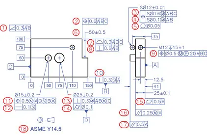
Image 3.0: Example for GD & T
In GD & T, the geometrical dimensioning and tolerances of the particular parts are provided. In addition, the information of Locating pins, rests, Clamps, Dumps, Slide information of each station and Sequence of opening of clamps, dumps and Slide stroke information are also provided.
In GD & T we will be learning about locating pins so where we can actually locate our pin units and best clamp. How the entire component is going to rest, or it's going to get clamped and dumb and slide information in each station sequencing and opening of clamp and slide Stroke information.
2) Part list:
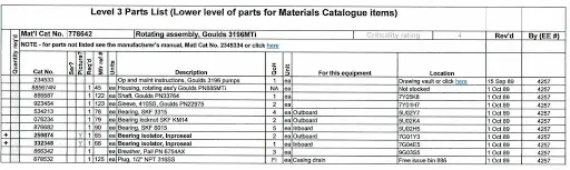
Image 3.1: Example for Part list
Part list states about the parts and assembly style. For example, first assembly is going to be between put in a panel and that which is going to get attached. And then the next one will be the hinge. So, every assembly will have a different section in it. So, we have to design different assembly parts. In the part list they are part numbers, part names are mentioned. Every part having different name.
3) Cad Files of Car Parts:
CAD files of cad products means the 3d component that we required from all the Cad parts.
4) Clamp Plan:
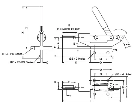
Image 3.2 Example for clamp plan
Clamp Plan is very important input that we get in the car products is where exactly we can place those clamping units are the particular pin Units. We should never change the position of the particular clamp or the pin, which is given in these data. We can change our design a little bit here or there, but we should not change the input design data about the clamp position or the pin position.
5) Product Assembly Process Sheet:
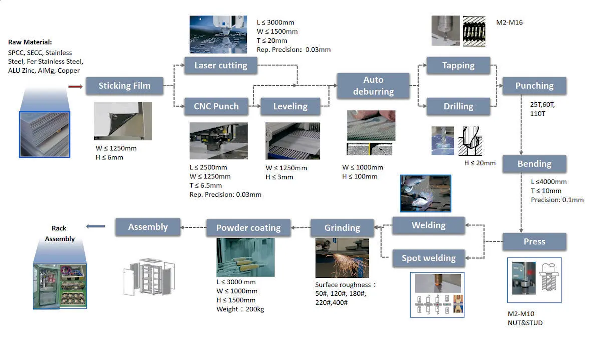
Image 3.3 : Example for product assembly process sheet
In the Product Assembly Process Sheet we find what kind of products we are going to assemble in that particular component or the particular Unit. The sequence of the assembly and stages of the assembly are properly mapped in this sheet.
4)What is the Clamp plan?
A clamp is a force-actuating mechanism of a fixture. The forces exerted by the clamps hold a part securely in the fixture against all other external forces. Clamping surfaces are subjected to the clamping forces for obtaining invariant location.
The Clamping plan of the part is the plan which defines the location of the clamp while doing the operation to ensure the geometry of the assembly. We can not change the clamp plan without the permission of the customer. We have to design fixture which should not required change in the clamp plan. Clamp plan provides information regarding to the location of pins, Rest, Clamps, Dumps and the coordinates of the clamp plan. which helps the design team while assembling and working with the fixture.
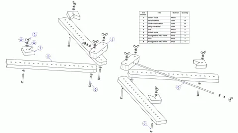
Image 4.0 : Typical clamp plan
5)What is the purpose of a Layout?
Layout is the physical arrangement of machines, processing equipment and service departments to achieve greatest co-ordination and efficiency of 4 M’s (Men, Materials, Machines and Methods) in a plant., either existing or in plans of industrial facilities.
Plant layout is a floor plan for determining and arranging the designed machinery and equipment of a plant in the best suitable place which allows the easy flow of material, at the lesser cost and time which improves efficiency of the work place
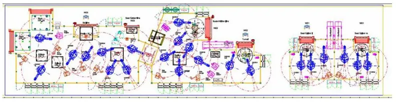
Image 5.0: Typical layout in a shop floor
The above image shows all the objects of manufacturing line like robots, Fixtures, Racks etc. & also shows the reachability of the robot to the fixtures also called the swept area of the robot. It also shows the constraint of space or the space available for the fixture that we are designing. Layout provides information about Flow of parts, Station pitch, Robot stations, Tool changers, Tip dressers, Platform height, Sub assembly links & loading/Unloading sequence.
6)What is Ergo data?
Ergonomics is the application of psychological and physiological principles to the engineering and design of products, processes, and systems. The goal of human factors is to reduce human error, increase productivity, and enhance safety and comfort with a specific focus on the interaction between the human and the thing of interest.
Ergo data is studied to identify and quantify ergonomics working postures that contributed to the serious development of muscle skeletal injuries and thus investigated possible contributory their related causes.
Let us take the final assembly of an automobile, it involves several processes. Manual labor is involved in some assembly operations. All the processes have to be improved continuously in order to reduce the costs and increase productivity. The workers attain various postures, exerts force and works continuously in cycle time to accomplish the assembly task. so, by taking all the ergo data and the work place layout and fixtures are to be designed to increase the productivity of manual labour and ensure labour safety.
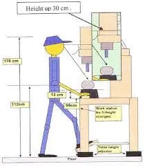
Image 6.0 Typical ergonomics data in a manufacturing process
7) What do you understand by Weld study?
weld study is a study of the particular gun that we are going to use for welding and where we are going to weld. So, if we doing a spot welding what kind of spot welding, we are going to do number of welding to the particular component. Weld study includes Weld Gun Details, Weld matrix and weld points and Geo weld points and Re-spot Weld Points.
1)Weld Gun Details:
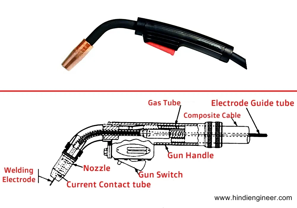
Image 7.0 Typical weld gun
This involves the study of the weld gun which includes weld gun details such as how to use where to use etc.
2)Weld matrix and weld points:
Weld points are the points where the welding is to be done and at which point i.e. at which coordinate.
3) Geo weld points and Re-spot Weld Points:
The data of weld matrix and weld points will be given to you in the form of spears i.e. Green and red spheres. Geo spots are Red in Color and Re spots are Green in color. All the red spheres are going to happen in geostationary. In the res-pot station where the green welding is going to happen. This happens when one component is to be assembled this particular component in one station and in the other station, the other component is to be attached.
8) What are the criteria for percentage completion in the designing stage?
Percentage completion criteria is a time plan / schedule which we define for completion of design. So, when we are going to complete the in entire designing, then we're going to move on to simulation on all these subcategories would be considered in percentage completion criteria like a probability to when we can complete the entire fixture design. The percentage completion criteria is categorized as follows
- 0-25% Input and concept design
- 25-40% Concept approval and simulation
- 40-85% Design freezing and detailing
- 85-100% Check and Final dispatch
Input and concept designing
In this they given four days to design the fixtures that means we have to complete 25% of the task within four days.
Concept approval and simulation
The concept of design is approved here, and the simulation check is done here, which is 25 to 40% of your design is complete in Concept approval and simulation.
Design freezing and detailing
In this process the design gets finalized. And the detailing is going to start again. Once the detailing is finished, and the design is also feezed that means you have completed at least 40 to 85% of task.
Check and Final dispatch
In this stage this is final stage, Here checking the quality check usage and the final dispatch, which is the output that we are going to give to the customer, which is from 85 to 100%.
9) Brief about "Output" in design?
In BIW fixture design or any industry. We don't only just design a particular component and just give the CAD file to the customer. We have to submit a lot of documents like 3d documents, 2d documents which details the part and other factors as well, like bill of material and other documents and the standards followed etc.
To be specific outputs in design should
- a) meet the input requirements for design and development,
- b) provide appropriate information for purchasing, production, and for service provision
- c) contain or reference product acceptance criteria, and
- d) specify the characteristics of the product that are essential for its safe and proper use.
The basic output are 3D models and the 2D drawing of the tools
1.Unitized Tools
In the unitized tools testing requires two types of drawing sheet, which is one key sheet and layout sheet. These sheets are an index of units and placements on the tool base. Layout sheet is a detailed drawing of that particular tool which shows details of components and how and where it is to be placed. Key sheet shows the placement and the location of that particular tool on the tool base where exactly the tool is placed. And what is his exact position in a particular place.
2.Non-Unitized Tools
Non unitized tools are basically tools like Stands and tool changers where you don't need key sheet. Tools that can stand alone and can be detailed completely on a layout. We can use to layout sheet and complete the entire documentation of the particular component.
10) What do you understand by structuring a design tree? How does it reduce errors during the design process?
Structuring a design tree implies to a process where all the assemblies & parts are named in a specific standard. Different customers have their different set of standards to structure a design tree. It is an important process which helps us to identify a specific part or assembly as to which project, tool or unit, it belongs to. This helps us to avoid the errors during design study, manufacturing, assembly, inspection etc.
If the parts or assemblies are not properly or the design tree is not structured properly, it will create confusion to understand the design & may create major possibilities of making an error. Naming of a fixture or a unit or a part, gives the information as to which project or zone or assembly do, they belong. It can help us to identify the quantity of items of same type or different types are being used in assembly.
The basic structure followed in structuring tree design was under the product there are main assemblies, Sub-assemblies, Child part, Standard parts etc. these all parts are provided with specific no, Zone etc. to identify easily.
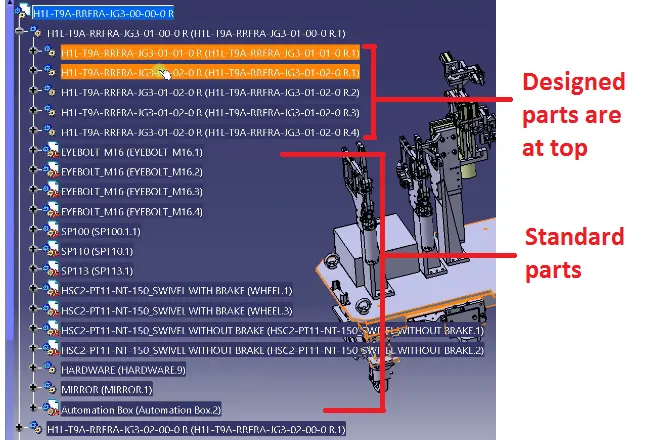
Image 10.0: Typical Design tree
From the above image the title is given as H1L-T9A-RRFRA-JG3-00-00-00 in which
H1L-T9A- The project name
RRFRA- Panel name
JG3- Jig no. 3
00- Unit no.
00- part no.
00- Component no.
11) What are Units? Mention 5 types of units.
A unit is a device that has a specified function, especially one forming part of a complex mechanism. The BIW fixtures is the assembly of different units which are designed to fulfill different purpose. In units they are two types one is unitized tools and non-unitized tools.
The unit have the specified function like resting the panel, clamping the part, Locating the part etc. According to the 3-2-1 principle of fixture design the units are designed to locate & clamp the car panel to its specified position in fixture while operation is going on.
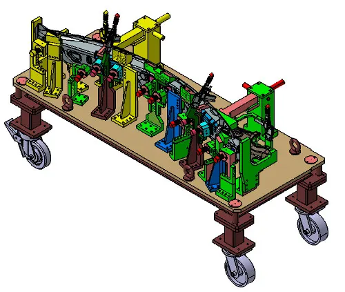
Image 11.0: Typical units in BIW fixture assembly
The basic units in BIW fixture design are as follows:
1) Fixed pin unit:
It is non movable locating unit used for proper location of the part and arrests the movements as well
2) Retract pin unit:
It is movable locating unit which have retracting mechanism. Which creates ease in assembling two components placed in different directions
3) Rough locator unit:
It roughly guides the operator for locating the part on the fixture.
4) Rest unit:
The panel is rest on this unit.
5) Base unit:
It is the unit on which all other units are mounted.
12) Describe Fixed Pin units & their purpose?
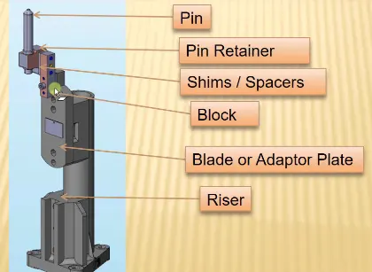
Image 12.0: Fixed pin unit
Fixed pin unit consist of riser, blade, block, shims or spacer, pin retainer & pin. Riser is the standard part which is used to rise up the height of the while unit. Blades are plates mounted on the riser. Other parts like cylinder, arms etc. are mounted on the blade. Shims are the small part which comes with the thickness of 0.1mm, 0.2mm, 0.5mm etc. These will compensate the stack up tolerance which reflects at the panel holding part called Mylars. In fixed pin shims are used to adjust to translational motions. Pin retainer will support the pin & the locating pin which restricts movement of the car panel.
Purpose of fixed pin unit:
- Fixed pin unit is a unit designed to locate the car panel using pin.
- The fixed pin unit is the part of the 3-2-1 principle. It restricts 6 degrees of freedom of the car panel.
- It is necessary to have 2 pins to locate car panel. one pin must arrest 4 way (4 translational) & other must arrest 2 way (2 rotational) of a car panel.
13) What are the different parts of a fixed unit?
Fixed unit consist of riser, blade, block, shims or spacer, pin retainer & pin.
1) Riser: Riser is the standard part which is used to rise up the height of the whole unit. Generally, risers are either made of plate fabrication or plate and tube welding together or from single gas cut plate.
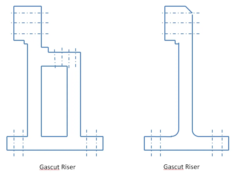
Image 13.0: Riser
2) Blades: These are plates mounted on the riser. Other parts like cylinder, arms etc. are mounted on the blade.
3) Block: Blocks can be machined to any desired fixture component. Because they come as a blank block, the possibilities are endless. Adding new tap holes or grinding down to your specifications are quick and simple.
3) Shims: These are the small part which comes with the thickness of 0.1mm, 0.2mm, 0.5mm etc. These will compensate the stack up tolerance which reflects at the panel holding part called Mylars. We give tolerance to all the parts of the fixture. Due to this tolerance the Mylars will either lift up or goes down from its defined position. If the Mylars goes down from the defined height it will make impression or dent on the panel. If the Mylars lift up then there will be a distortion due to welding stress. To adjust the Mylars At its defined position we use shims so the panel won't deformed & also don’t get any impression on it.
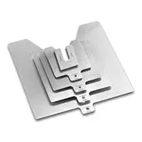
Image 13.1: shims
4) Pin retainer: It will support the pin.
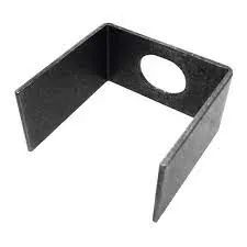
Image 13.2: Pin retainer
5) Locating Pin: Typically, locating pins are used for controlled, fine tolerance positioning of a work piece. For example, a pallet that is moved along one axis, where the drive mechanism is not accurate and stable enough to place it in a position sufficiently accurate to execute a particular process, the use of locating pins may be the best solution. The Diamond Shape is a critical feature that helps with machining inaccuracies and smoother locating operation. When two round head pins are installed onto one plate, the distance between two mounting holes must be extremely precise and even then, the work piece will not be placed on the base as easily as it would with the use of a diamond shape pin.
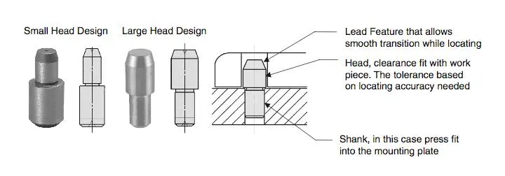
Image 13.3: locating pin
14) What is the purpose of making a Rest unit & describe its parts?
The rest units are designed to rest/support the car panel by using NC blocks/Mylar/Rest. It is the simplest unit to design with less parts. Because of this simplicity the rest unit is combined with other unit to reduce the cost of the overall project. It can be combined with clamp unit to clamp as well as to rest the car panel. It can be combined with locating unit to locate as well as to rest the car panel. also locating, clamping & rest unit can be combined together in one unit to reduce cost.
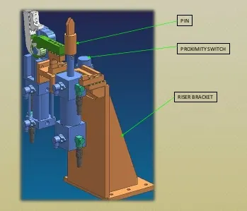
Image 14.0: Rest unit
The major parts in rest unit are
1) Riser: Riser is the standard part which is used to rise up the height of the while unit.
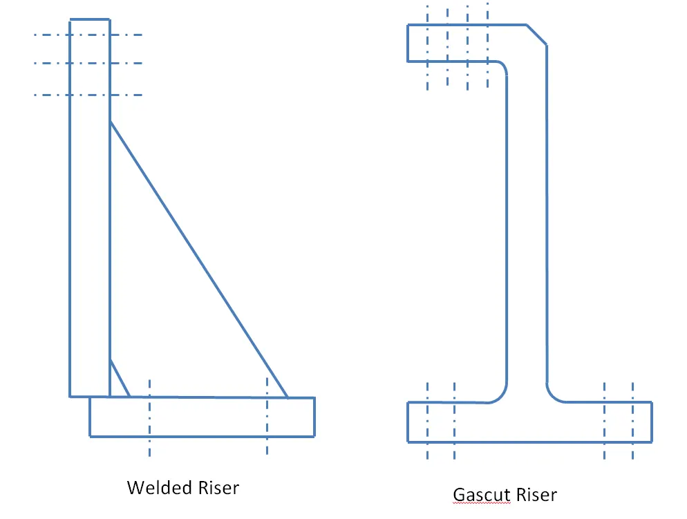
Image 14.0: Riser
2) Blades: These are plates mounted on the riser. Other parts like cylinder, arms etc. are mounted on the blade.
3) Shims: These are the small part which comes with the thickness of 0.1mm, 0.2mm, 0.5mm etc. These will compensate the stack up tolerance which reflects at the panel holding part called Mylars. Shims are used in one in direction in rest unit which is up & down because it requires adjustment in height only.
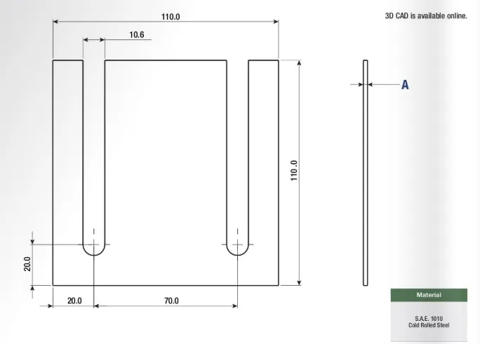
Image 14.0: shims
4) Mylars: Mylars is the component which holds the panel while operation. These are placed from top side & from bottom side also. The top side Mylars called as Clamping Mylars & the bottom side Mylars called as Resting Mylars. Every clamping Mylars have resting Mylars. It don’t allow deformation of the part due to welding stresses.
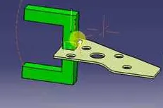
Image 14.0: Mylars
15) What are the basic fundamentals to design a Sensor unit?
Sensor is a device which detects or measures a physical property and records, indicates, or otherwise responds to it. A unit designed to sense car panel using electrical sensors is called sensor unit. The from the sensors is send to the PLC so the next process is executed by this signal.
There are different types of sensors such as proximity sensor, laser sensor, photo electric sensor, infrared sensor etc.
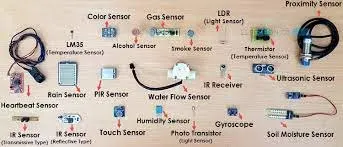
Image15.0: sensors
Fundamentals of Sensor Unit Design
Every single Loose panel, which are being welded in a tool should be sensed. So, every single panel that we are going to assemble in that particular panel.
For example, if there are nine different panels to assemble in one panel. Every single one of those panels should have one sensor attached to it. Each panel should be sensed by one or two sensors depending on the size of the panel. If a component is really small one sensor is sufficient to detect that particular panel. If the panel is really big. we will use two sensors towards the opposite directions of each to sense their particular panel. Hence every sensor should be mounted in three directional (upward, downward, right and left) adjustable ways.
16) What is a Rough locator unit & what are the basic fundamentals to consider while designing it?
A rough locator is a part designed to guide the operator, to locate the car panel on to the pins accordingly. A rough locator can be of standard part or make part. It can be called as fool proofing method also. Because due to the rough locator the part cannot be loaded in correct position. The rough locators are set according to the angle of the respective panel hence part can only be loaded in defined direction & orientation.
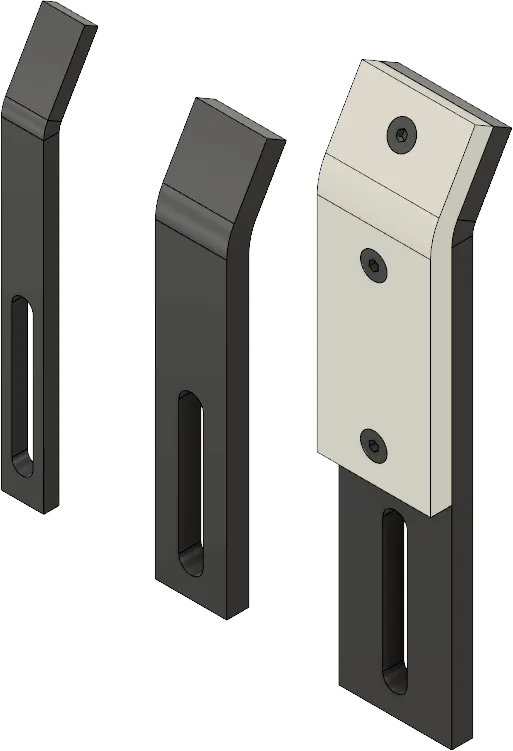
Image 16.0: Rough locators
Fundamentals of rough locator design
- Rough locator should be placed at the edges of the car panel, which it has to guide.
- They should be placed in the same angle of the car part edge with a minimum distance of 2-5 mm from the edge of the car part.
- It should guide the panel in pin arresting direction.
- Rough locator should start guiding the panel before 10 to 15mm to the start of the pin engagement. Rough locator should be designed with entry angle for the car panel. Generally, it ranges between 30-45 degree.
- Rough locator should be designed with two slots to mount the easy adjustments.
- The slots should be in the direction of car part guiding.
17) What is a Base unit and describe it's parts?
A base unit is the unit designed to mount all the other units such as Clamp unit, Pin unit, rest unit etc. and also other parts necessary for a tool like pneumatic valve box, trunking cable path will also be mounted on to a base unit.
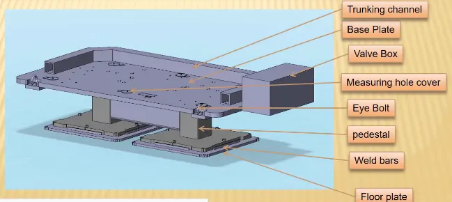
Image 17.0: Base unit
Base unit’s parts are as follows
1) Floor plate: It is the plate which join the fixture to the floor by using some nut bolts. This plate surface is machined for maintaining the horizontal position of the fixture.
2) Weld bars & pedestal: Pedestal is the base or support on which the fixture is mounted.
3) Eyebolt: An eye bolt is a bolt with a loop at one end. They are used to firmly attach a securing eye to a structure, so that ropes or cables may then be tied to it. Machinery eye bolts are fully threaded and may have a collar, making them suitable for use with angular loads up to 45°. Eye bolts without a shoulder should not be used for angular loads.
4) Measuring hole cover: The base plate has some drills to mount various units like clamp, rest, pin etc. & every drill have some coordinates to define the exact location of the hole. Due to irregular shape of the car panel the drilled holes coordinates are not like 110.0, 150.0 But it like 110.62,150.84. The measuring hole is drilled over the base plate which having exact coordinates so that all other holes can take reference from it. The measuring hole no. depends on the size of base plate. These holes are covered by using some plate to protect against dust, damage etc.
5) Valve box & trunking channel: The valve box is the box which includes different solenoid valves. The pneumatic fixtures work on air pressure provided to it. So, the arrangement of air pressure inlet & outlet is done within this valve box. The trunking channel includes all the pressure inlet cables going to the pneumatic parts of the fixture & protects them from damaging while operation is in process.
6) Base plate: Base plate is the heavy plate of large thickness because it carries all the weight of the mounted parts. So, it must be able to bear the load. Base plate is machined to maintain the parallelism within the tolerance. It also consists some drilled holes to mount the different units over it.
18) What is a Dump Unit and what are its functions?
Dump unit is the complex unit to design due to space constrains there is less space available & have to adjust all the parts in available space. It consists of dump cylinder to perform the operation of clamping & unclamping car panel.
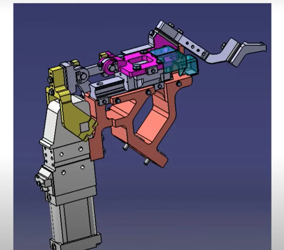
Image 18.0: Damp unit
Functions of Dump Unit
if you have particular constraint and you cannot assemble in a normal way then dump unit comes into action. It has dumb cylinder and it has open position and closed position. And it has Clamp Cylinder Unit too. That is why this are very complex and design. if you have any geometrical constraints, you can use this dampener to constrain your components.
19) What is a Slide unit? Mention where Slide units are commonly used.
Slide units are positioning units which are used to position the fixture, weld gun, units, robots into position for further operations. Slide unit consists of sliding cylinder which has one open position and one closed position, which has to guide rails direction to the entire panel is going to move, Position locking unit which will lock the position at that particular point doesn't allow the entire plate to move, sensors to sense whether this entire component has reached here or not. stopper blocks restrict the motion at the ends. These are commonly used in automotive assembly where different sized components can e worked on single unit
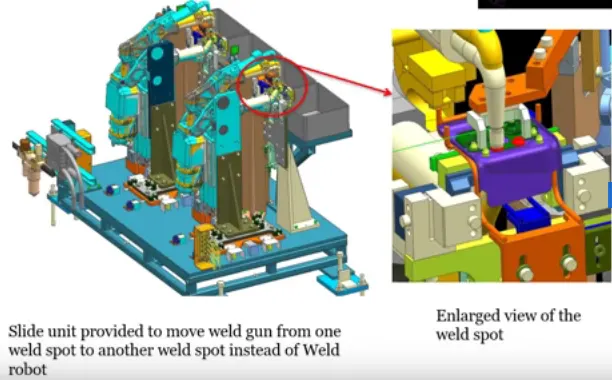
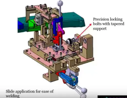
Image 19.0 Slide unit