Exo-skeleton suite Assembly
Modeling and Assembly of Exo-skeleton Suit
What is Exo-Skeleton suit?
- It is a wearable mobile machine
- It works on Pneumatics/Hydraulics/Motors
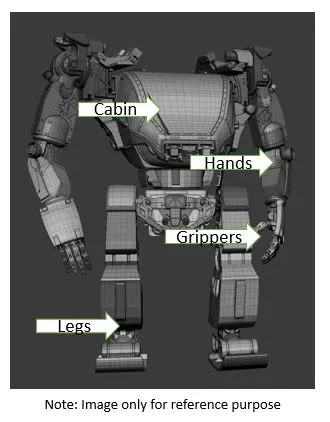
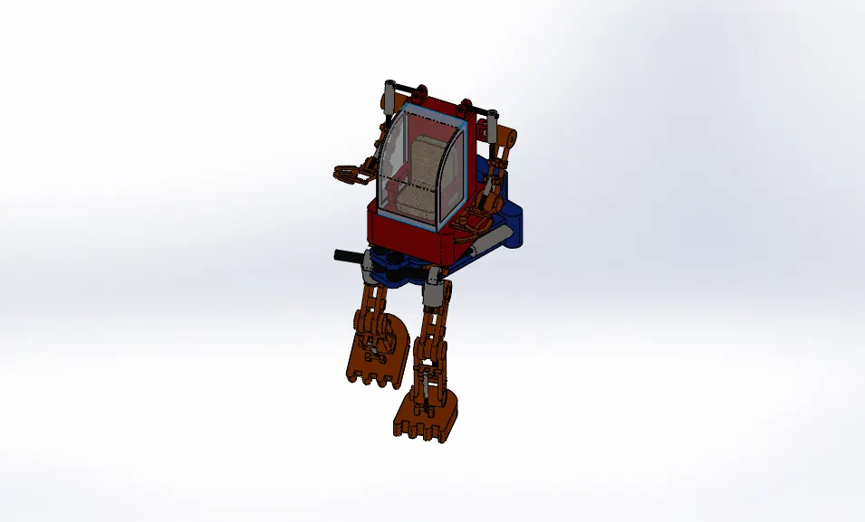
- It consists of a cabin, pair of legs and hands and grippers
Aim and Objective:
- To model the cabin, pair of legs and hands, grippers along with the pneumatic cylinders and assemble the parts
- The objective of the project is to understand and simplify the complexity in assembly of multiple small parts
Details of the project:
- Upper arm is fixed to the body and lower arm is connected to the upper arm at the elbow joint. A piston cylinder is connected to both the upper arm and lower arms for their movements.
- Grippers are attached to the hand i.e. at the end of lower arm and their movements are handled by piston cylinders
- The whole upper main body is connected to the base with the help of the shaft. Two pistons will be connected to the upper body on base for sideward movements of the upper body
- Leg joints are connected to the base and piston cylinders connected to the legs allow the movements for walking
Introduction of software:
Solid works: Solid works is a product of Dassault systems company. It is a software used for designing, assembling and real time rendering of the real time models. Any kind of complicated and sensitive designs can be easily modeled using the tools and interface of this software. The basic tools and its usage is explained in the description section
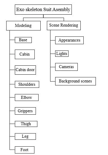
Design methodology:
Description:
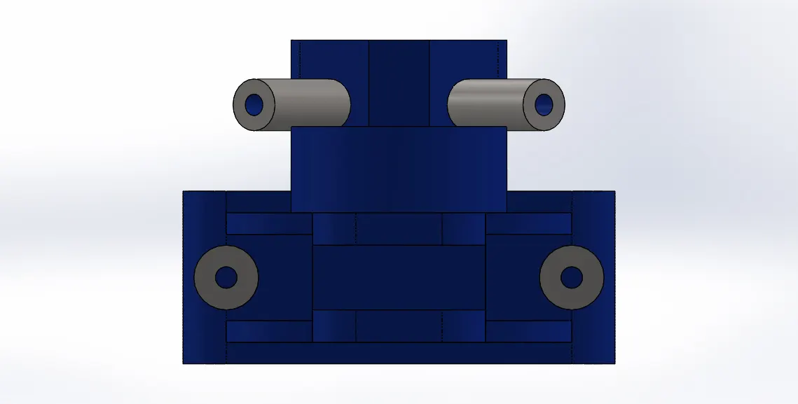
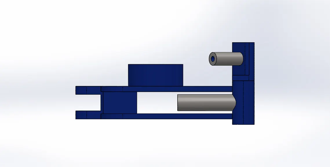
Base:
Front view
Side view
Isometric view
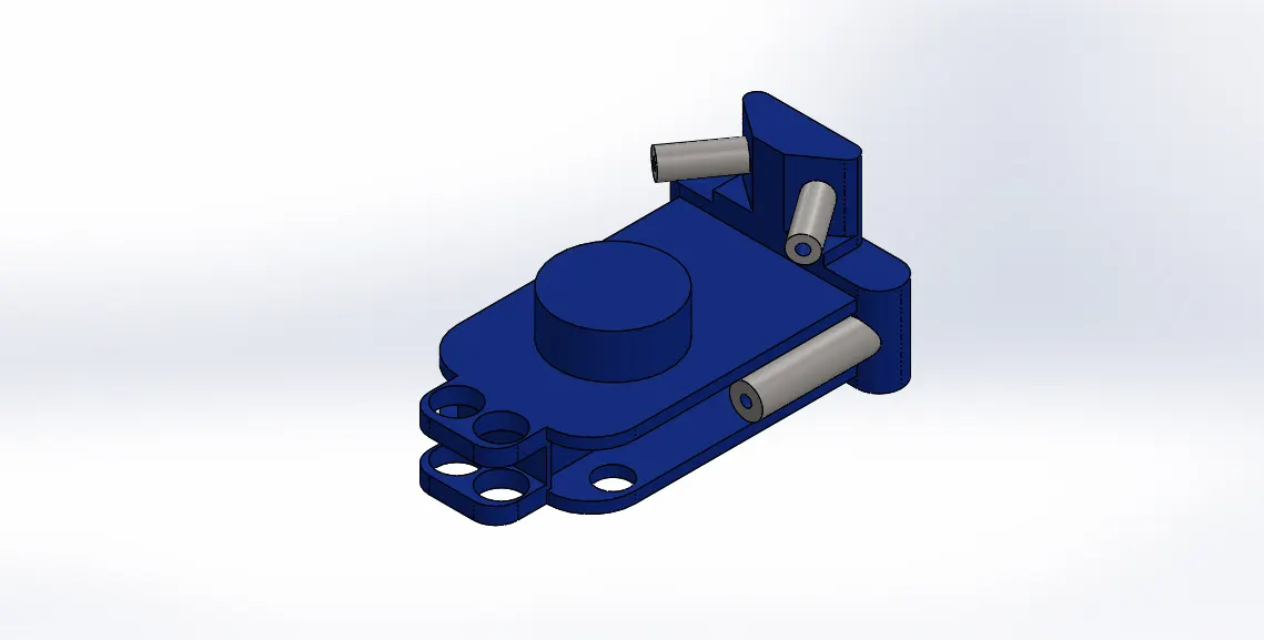
Tools & Features used:
Sketch: To create required sketches
Line: To drawing lines and construction lines
Circle: To draw circles
Boss-Extrude: To obtain 3d solid from 2d sketch
Cut-Extrude: To subtract a solid portion from a solid using 2d sketch
Reference plane: To construct a reference plane if existed references are not suitable or far away
Mirror: To mirror features or sketches along the selected reference
Fillet: To convert sharp internal or external edges into smooth or round edges
Smart dimensions: To add or edit dimensions of sketches
Cabin:
Front view
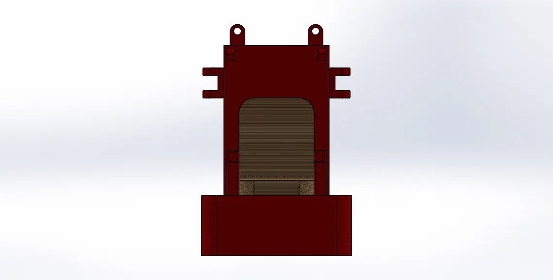
Side view
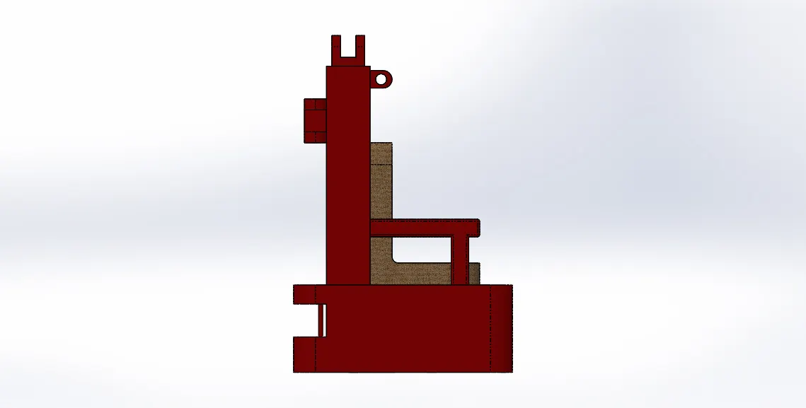
Isometric view
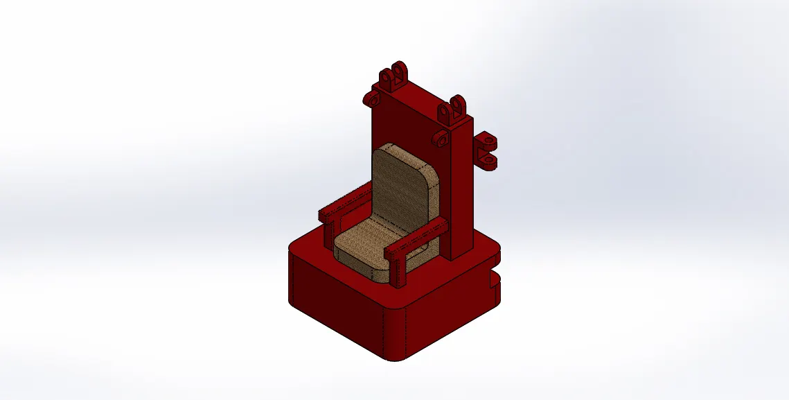
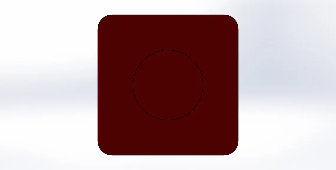
Bottom View
Tools & Features used:
Sketch: To create required sketches
Line: To drawing lines and construction lines
Circle: To draw circles
Boss-Extrude: To obtain 3d solid from 2d sketch
Cut-Extrude: To subtract a solid portion from a solid using 2d sketch
Reference plane: To construct a reference plane if existed references are not suitable or far away
Mirror: To mirror features or sketches along the selected reference
Fillet: To convert sharp internal or external edges into smooth or round edges
Smart dimensions: To add or edit dimensions of sketches
Cabin door:
Front view
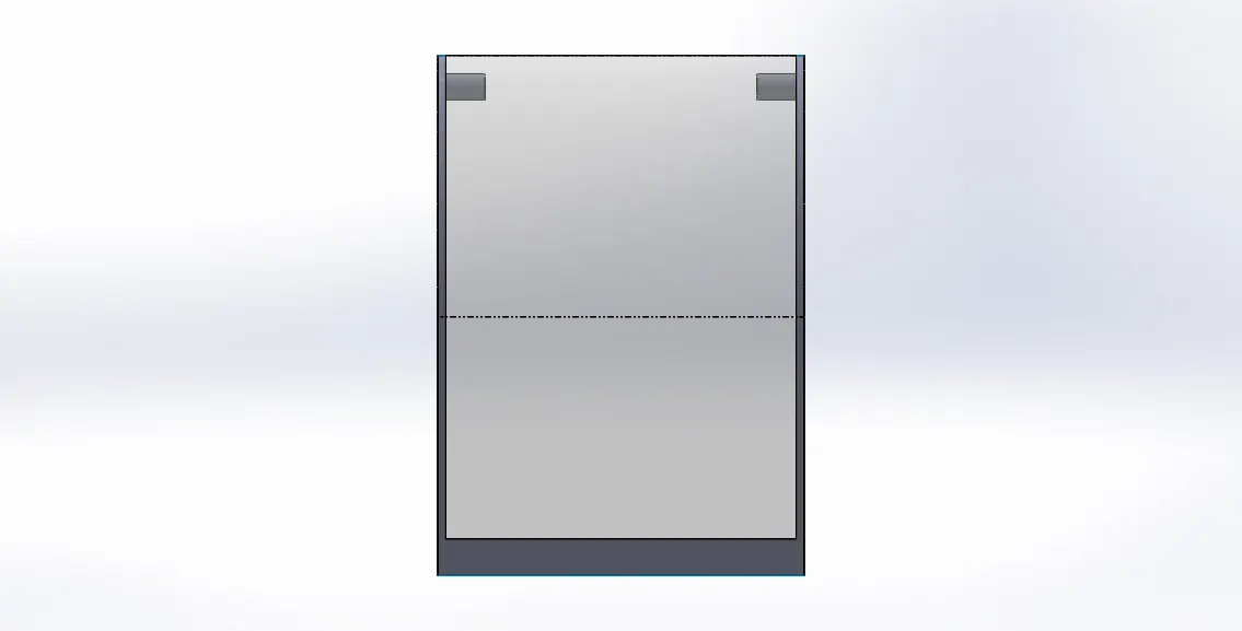
side view
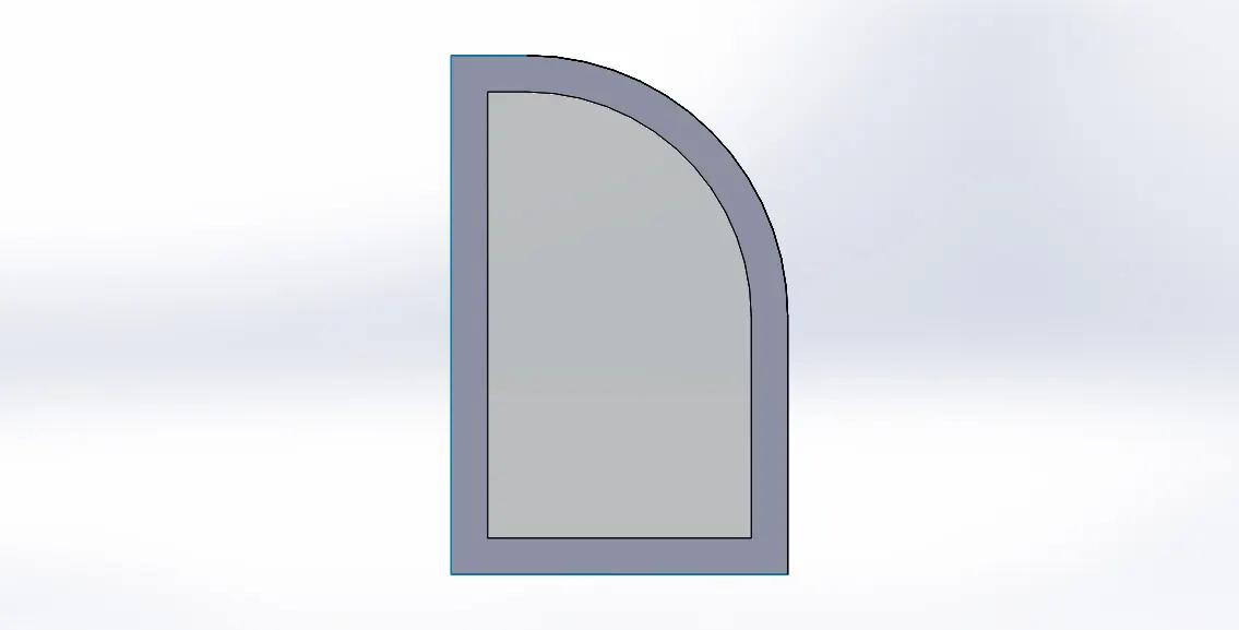
Isometric view
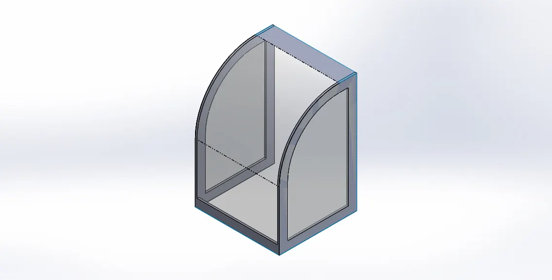
Tools & Features used:
Sketch: To create required sketches
Line: To drawing lines and construction lines
Arc: To draw arcs
Boss-Extrude: To obtain 3d solid from 2d sketch
Cut-Extrude: To subtract a solid portion from a solid using 2d sketch
Reference plane: To construct a reference plane if existed references are not suitable or far away
Mirror: To mirror features or sketches along the selected reference
Fillet: To convert sharp internal or external edges into smooth or round edges
Ruled surface: To create new suface from selected edges
Smart dimensions: To add or edit dimensions of sketches
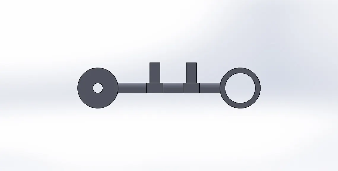
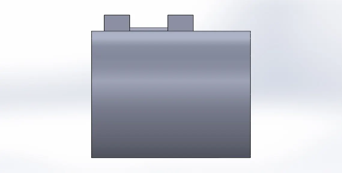
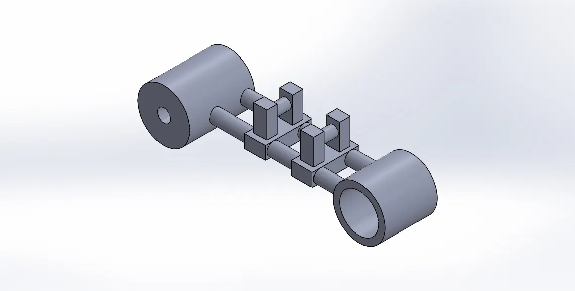
Shoulder:
Front view
side view
Isometric view
Tools & Features used:
Sketch: To create required sketches
Line: To drawing lines and construction lines
Circle: To draw circles
Boss-Extrude: To obtain 3d solid from 2d sketch
Cut-Extrude: To subtract a solid portion from a solid using 2d sketch
Reference plane: To construct a reference plane if existed references are not suitable or far away
Smart dimensions: To add or edit dimensions of sketches
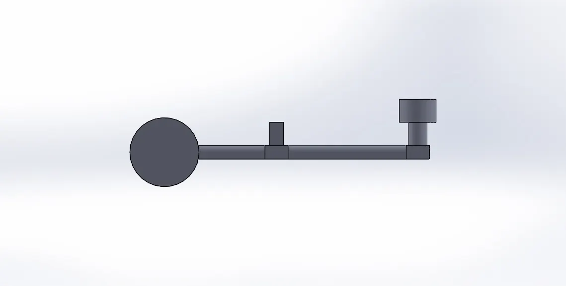
Elbow:
Front view
side view
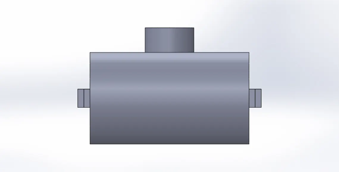
Isometric view
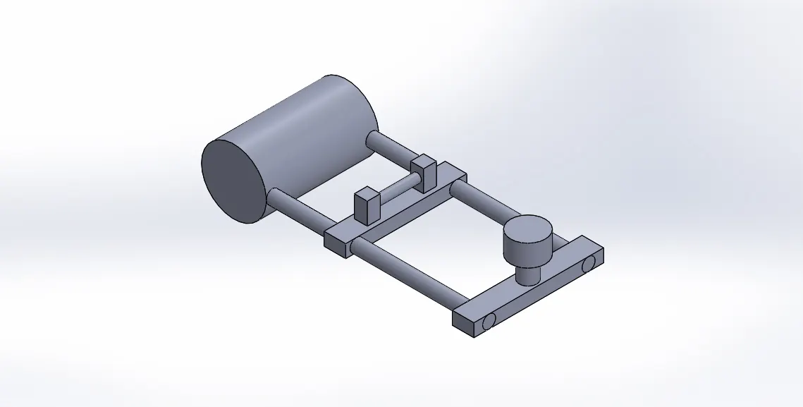
Tools & Features used:
Sketch: To create required sketches
Line: To drawing lines and construction lines
Circle: To draw circles
Boss-Extrude: To obtain 3d solid from 2d sketch
Cut-Extrude: To subtract a solid portion from a solid using 2d sketch
Reference plane: To construct a reference plane if existed references are not suitable or far away
Smart dimensions: To add or edit dimensions of sketches
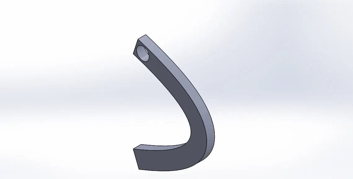
Gripper:
Front view
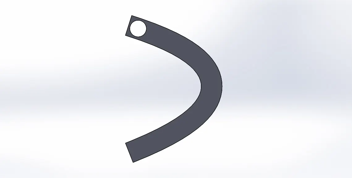
side view
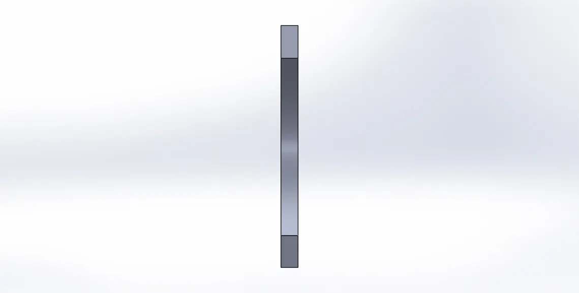
Isometric view
Tools & Features used:
Sketch: To create required sketches
Line: To drawing lines and construction lines
Circle: To draw circles
Boss-Extrude: To obtain 3d solid from 2d sketch
Cut-Extrude: To subtract a solid portion from a solid using 2d sketch
Reference plane: To construct a reference plane if existed references are not suitable or far away
Smart dimensions: To add or edit dimensions of sketches
Thigh:
Front view
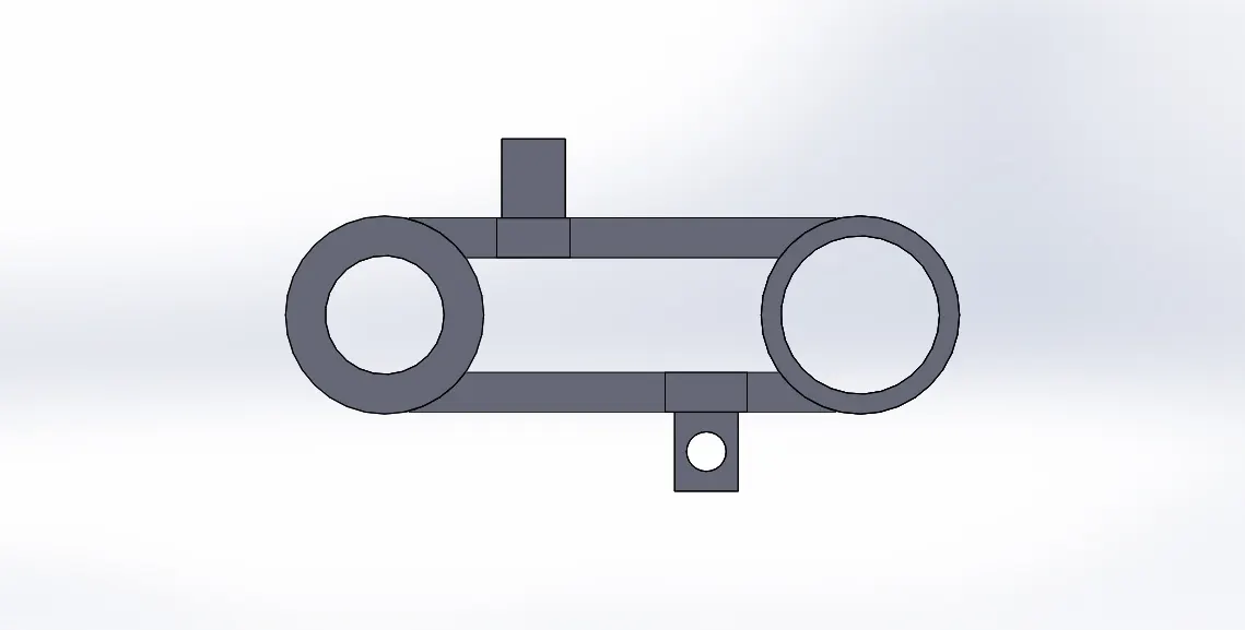
side view
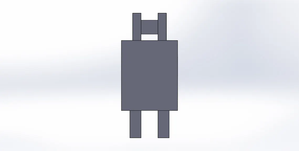
Isometric view
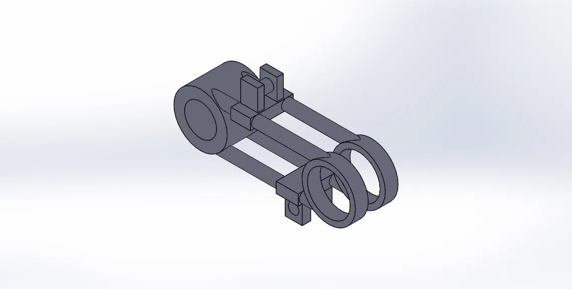
Tools & Features used:
Sketch: To create required sketches
Line: To drawing lines and construction lines
Circle: To draw circles
Boss-Extrude: To obtain 3d solid from 2d sketch
Cut-Extrude: To subtract a solid portion from a solid using 2d sketch
Reference plane: To construct a reference plane if existed references are not suitable or far away
Smart dimensions: To add or edit dimensions of sketches
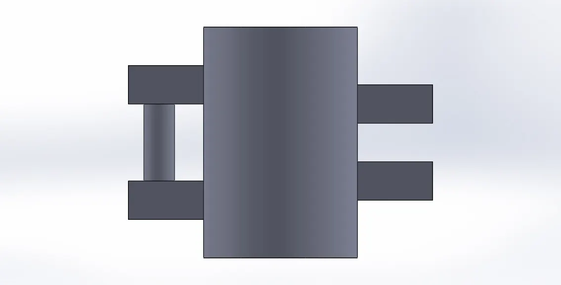
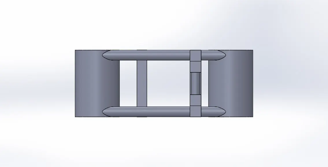
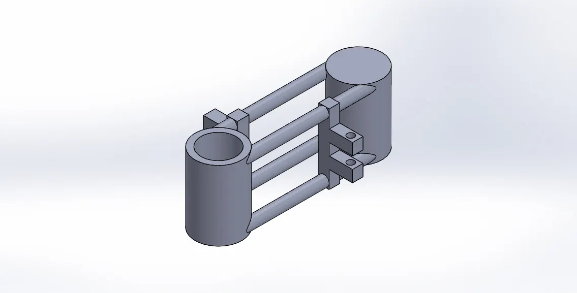
Leg:
Front view
side view
Isometric view
Tools & Features used:
Sketch: To create required sketches
Line: To drawing lines and construction lines
Circle: To draw circles
Boss-Extrude: To obtain 3d solid from 2d sketch
Cut-Extrude: To subtract a solid portion from a solid using 2d sketch
Reference plane: To construct a reference plane if existed references are not suitable or far away
Smart dimensions: To add or edit dimensions of sketches
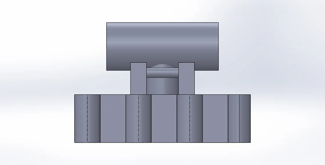
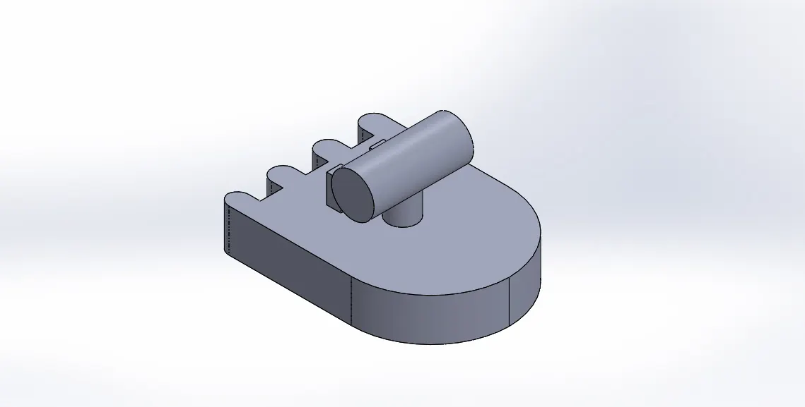
Foot:
Front view
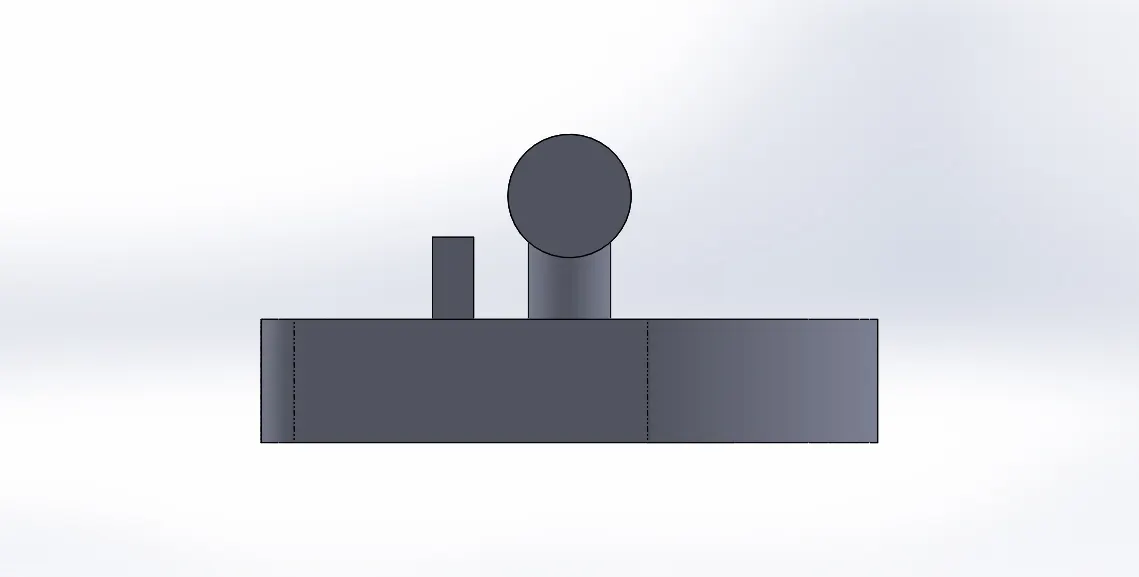
side view
Isometric view
Tools & Features used:
Sketch: To create required sketches
Line: To drawing lines and construction lines
Circle: To draw circles
Boss-Extrude: To obtain 3d solid from 2d sketch
Cut-Extrude: To subtract a solid portion from a solid using 2d sketch
Reference plane: To construct a reference plane if existed references are not suitable or far away
Smart dimensions: To add or edit dimensions of sketches
Assembly:
Front view
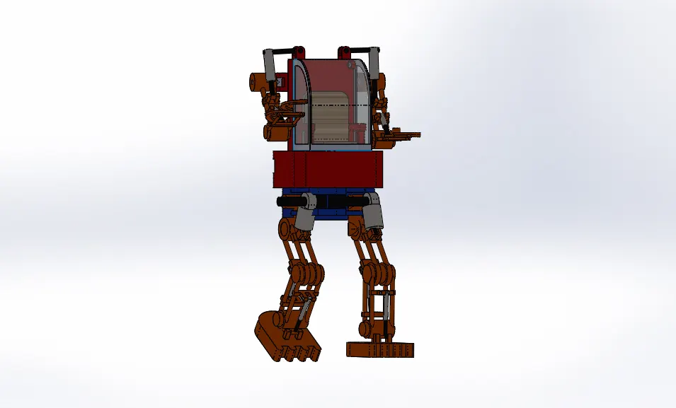
Side view
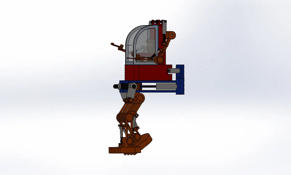
Isometric view
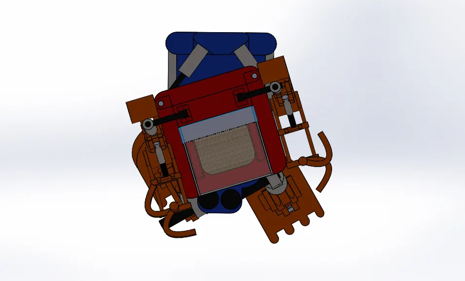
Top view
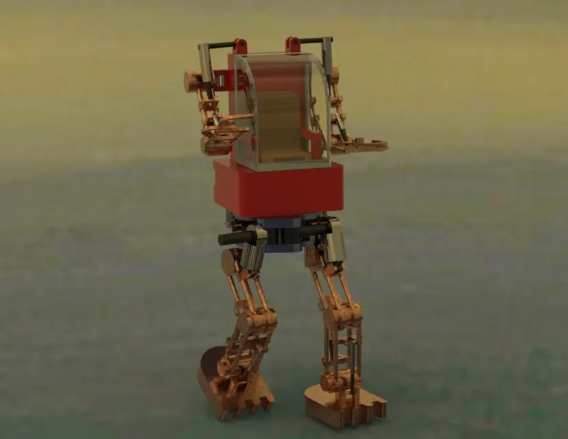
Render with environment
Tools & Features used:
Mates: To create constraints between surfaces
Conclusion:
Thus the Exo-skeleton suit is modelled, assembled and rendered using solid works software
Part file & Assembly files link : Exo-skeleton Assmebly