Assembly of Chopper Model
Assembly of Chopper Model
Objective:
- To design individual parts of the chopper with fully defined sketches and appropriate appearances.
- To assemble all the individual parts of the chopper model by assigning suitable constraints.
- To render the chopper model by adding appearances, decals, lights, cameras, and background scenes.
Introduction:
Solid works: Solid works is a product of Dassault systems company. It is a software used for designing, assembling and real time rendering of the real time models. Any kind of complicated and sensitive designs can be easily modeled using the tools and interface of this software. The basic tools and its usage are explained in the description section
Chopper model: Chopper is a customized bike which has a powerful engine and simple parts with high precise shapes and edges. The basic parts in the chopper are chassis, engine, front wheel, front fender, rear wheel, rear fender, oil tank, gas tank, front fork, chain part, pedal, transmission belt & kick stand
Design methodology:
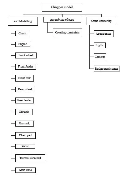
Description:
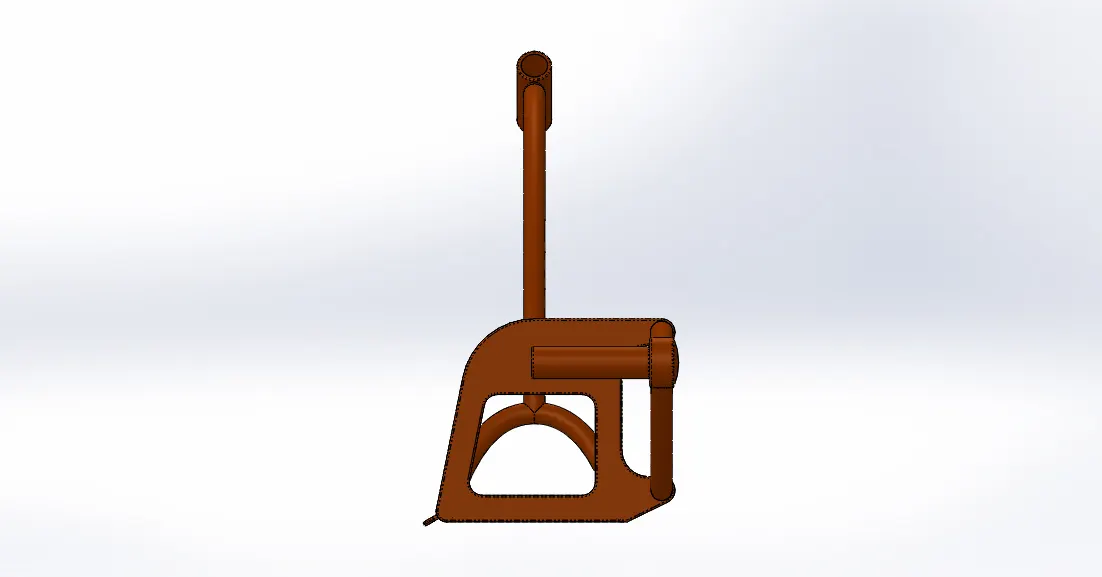
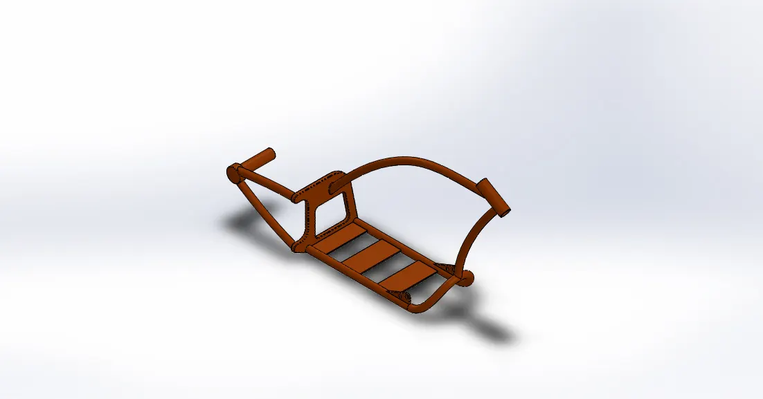
Chassis:
Front view
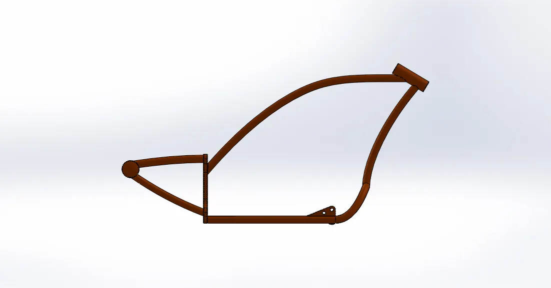
Side view
Isometric view
Tools & Features used:
Sketch picture: To insert pictures for reference
Sketch: To create required sketches
Line: To drawing lines and construction lines
Circle: To draw circles
Spline: To draw curves through interpolation of points
Intersection curve: To get an intersection curve obtained from projection of two curves
Boss-sweep: To obtain a solid body along the profile path
Boss-Extrude: To obtain 3d solid from 2d sketch
Cut-Extrude: To subtract a solid portion from a solid using 2d sketch
Reference plane: To construct a reference plane if existed references are not suitable or far away
Mirror: To mirror features or sketches along the selected reference
Split: To separate or split solid bodies
Combine: To combine or merge solid bodies
Dome: To create dome surfaces on flat surfaces
Fillet: To convert sharp internal or external edges into smooth or round edges
Chamfer: To convert sharp edges into bevel edges
Smart dimensions: To add or edit dimensions of sketches
Engine:
Front view
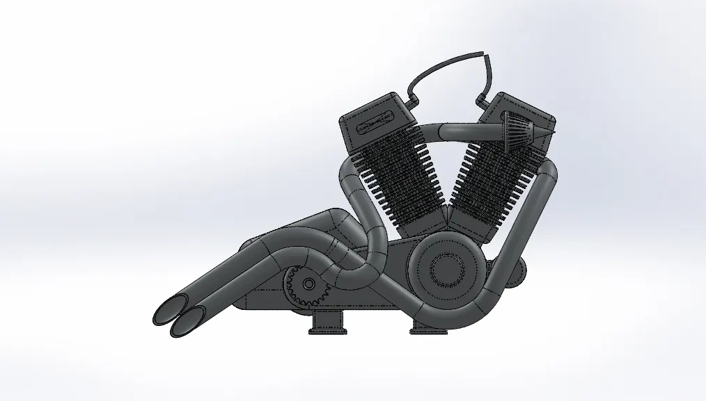
Side view
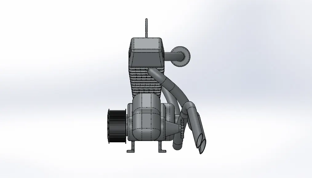
Isometric view
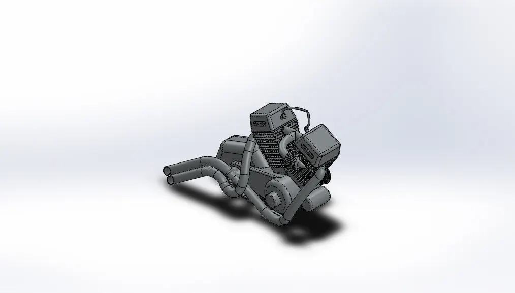
Tools & Features used:
Sketch picture: To insert pictures for reference
Sketch: To create required sketches
Line: To drawing lines and construction lines
Circle: To draw circle
Arc: To draw arc
Spline: To draw curves through interpolation of points
Convert Entities: To convert edges or curves into lines
Intersection curve: To get an intersection curve obtained from projection of two curves
Boss-sweep: To obtain a solid body along the profile path
Boss-Extrude: To obtain 3d solid from 2d sketch
Boss-Revolve: To revolve 2d sketch along the reference to obtain solid body
Cut-Extrude: To subtract a solid portion from a solid using 2d sketch
Reference plane: To construct a reference plane if existed references are not suitable or far away
Mirror: To mirror features or sketches along the selected reference
Split: To separate or split solid bodies
Combine: To combine or merge solid bodies
Dome: To create dome surfaces on flat surfaces
Fillet: To convert sharp internal or external edges into smooth or round edges
Chamfer: To convert sharp edges into bevel edges
Circular pattern: To create a pattern of feature or body along a circular reference
Linear Pattern: To create a pattern of feature or body along a linear reference
Composite curve: To obtain combined composite curve from two or more curves
Smart dimensions: To add or edit dimensions of sketches
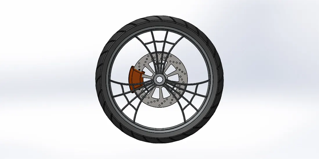
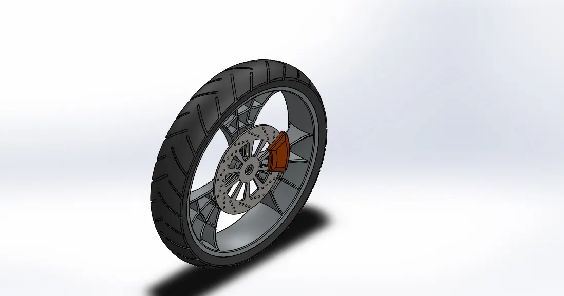
Front wheel:
Front view
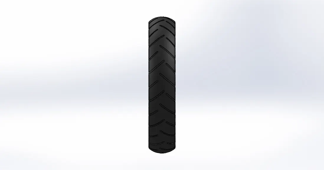
Side view
Isometric view
Tools & Features used:
Sketch: To create required sketches
Line: To drawing lines and construction lines
Circle: To draw circles
Arc: To draw arc
Spline: To draw curves through interpolation of points
Convert Entities: To convert edges or curves into lines
Offset Entities: To offset edges or lines to duplicate the edges
Boss-Extrude: To obtain 3d solid from 2d sketch
Boss-Revolve: To revolve 2d sketch along the reference to obtain solid body
Cut-Extrude: To subtract a solid portion from a solid using 2d sketch extrusion
Cut-Revolve: To subtract a solid portion from a solid using 2d sketch revolve
Combine: To combine or merge solid bodies
Fillet: To convert sharp internal or external edges into smooth or round edges
Chamfer: To convert sharp edges into bevel edges
Circular pattern: To create a pattern of feature or body along a circular reference
Linear Pattern: To create a pattern of feature or body along a linear reference
Smart dimensions: To add or edit dimensions of sketches
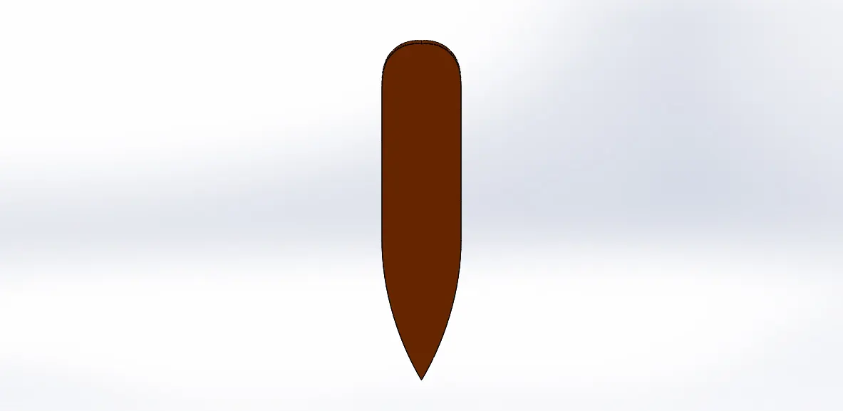
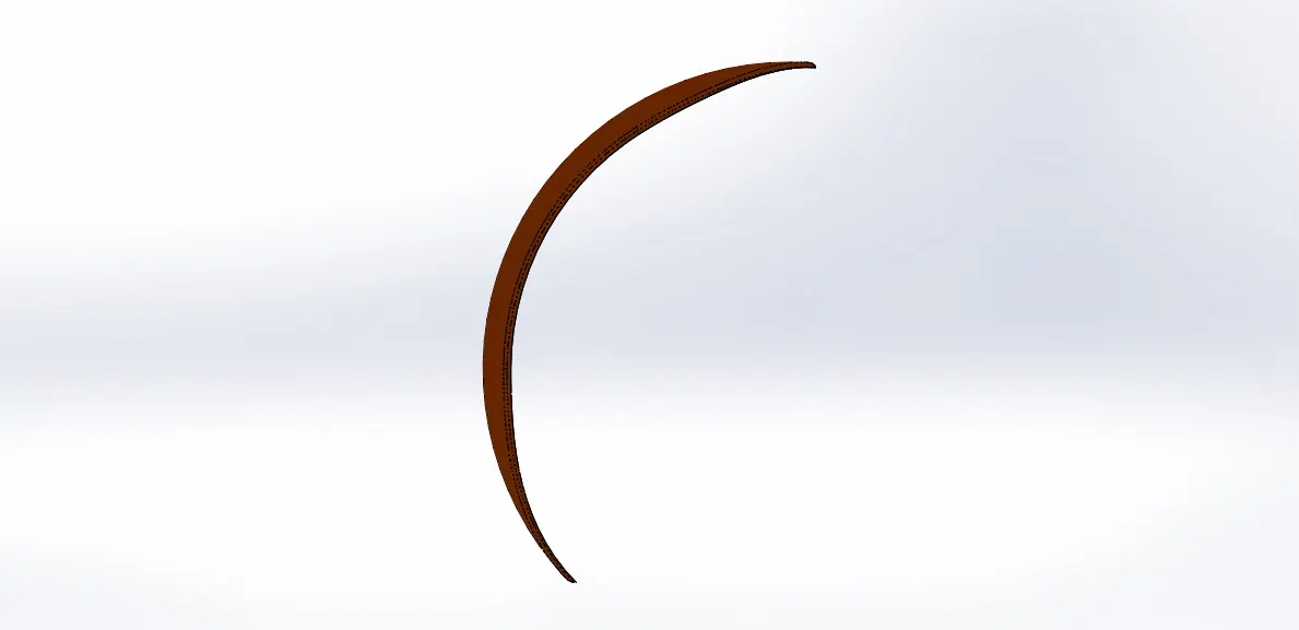
Front fender:
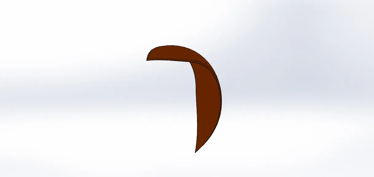
Front view
Side view
Isometric view
Tools & Features used:
Sketch: To create required sketches
Line: To drawing lines and construction lines
Spline: To draw curves through interpolation of points
Split: To separate or split solid bodies
Fillet: To convert sharp internal or external edges into smooth or round edges
Boss-Revolve: To revolve 2d sketch along the reference to obtain solid body
Smart dimensions: To add or edit dimensions of sketches
Rear wheel:
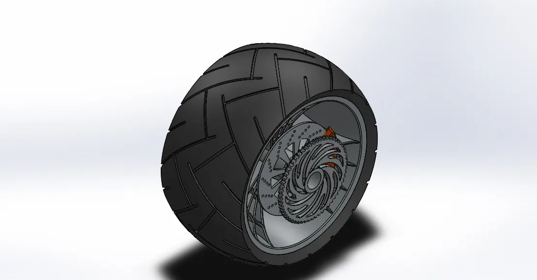
Front view
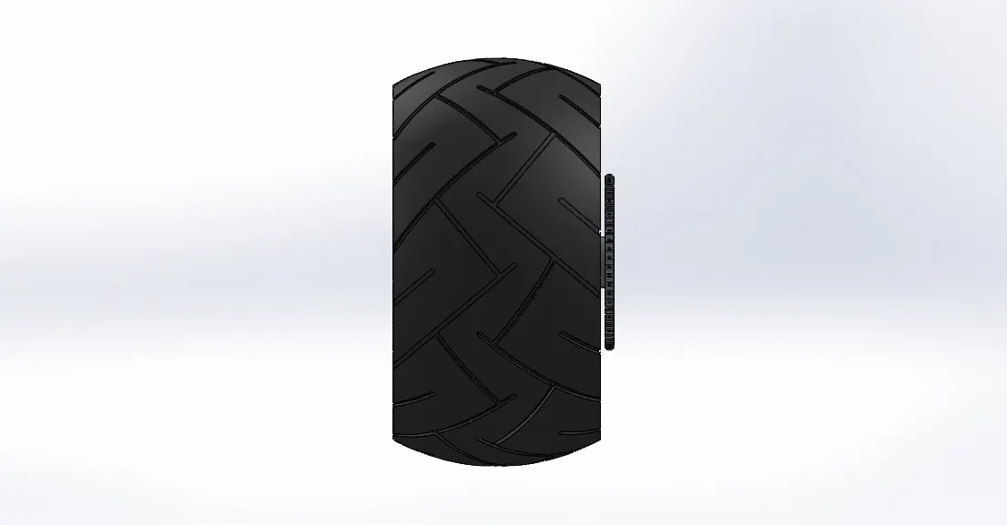
Side view
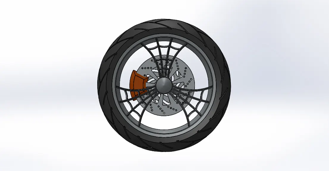
Isometric view
Tools & Features used:
Sketch: To create required sketches
Line: To drawing lines and construction lines
Spline: To draw curves through interpolation of points
Convert Entities: To convert edges or curves into lines
Offset Entities: To offset edges or lines to duplicate the edges
Boss-Extrude: To obtain 3d solid from 2d sketch
Boss-Revolve: To revolve 2d sketch along the reference to obtain solid body
Cut-Extrude: To subtract a solid portion from a solid using 2d sketch extrusion
Cut-Revolve: To subtract a solid portion from a solid using 2d sketch revolve
Combine: To combine or merge solid bodies
Fillet: To convert sharp internal or external edges into smooth or round edges
Chamfer: To convert sharp edges into bevel edges
Circular pattern: To create a pattern of feature or body along a circular reference
Linear Pattern: To create a pattern of feature or body along a linear reference
Smart dimensions: To add or edit dimensions of sketches
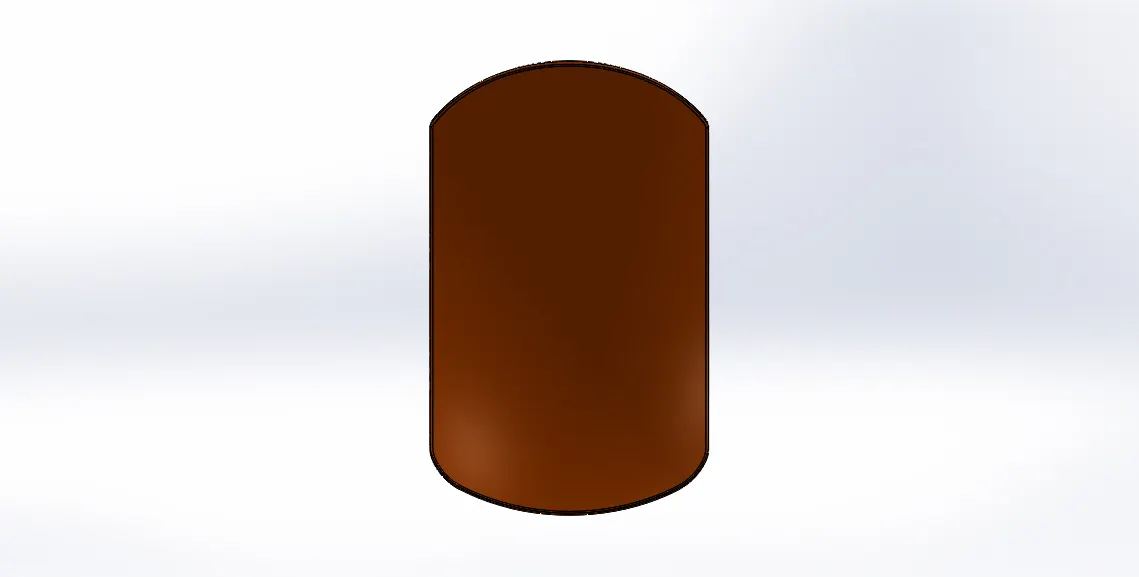
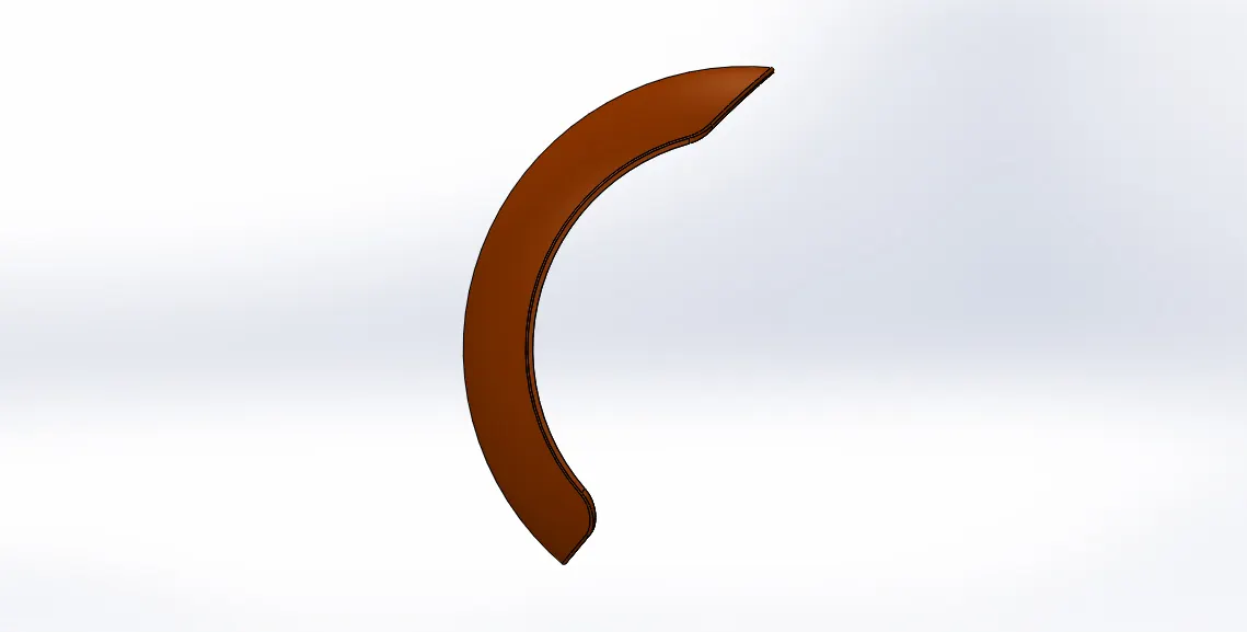
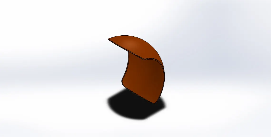
Rear fender:
Front view
Side view
Isometric view
Tools & Features used:
Sketch: To create required sketches
Line: To drawing lines and construction lines
Spline: To draw curves through interpolation of points
Split: To separate or split solid bodies
Fillet: To convert sharp internal or external edges into smooth or round edges
Boss-Revolve: To revolve 2d sketch along the reference to obtain solid body
Smart dimensions: To add or edit dimensions of sketches
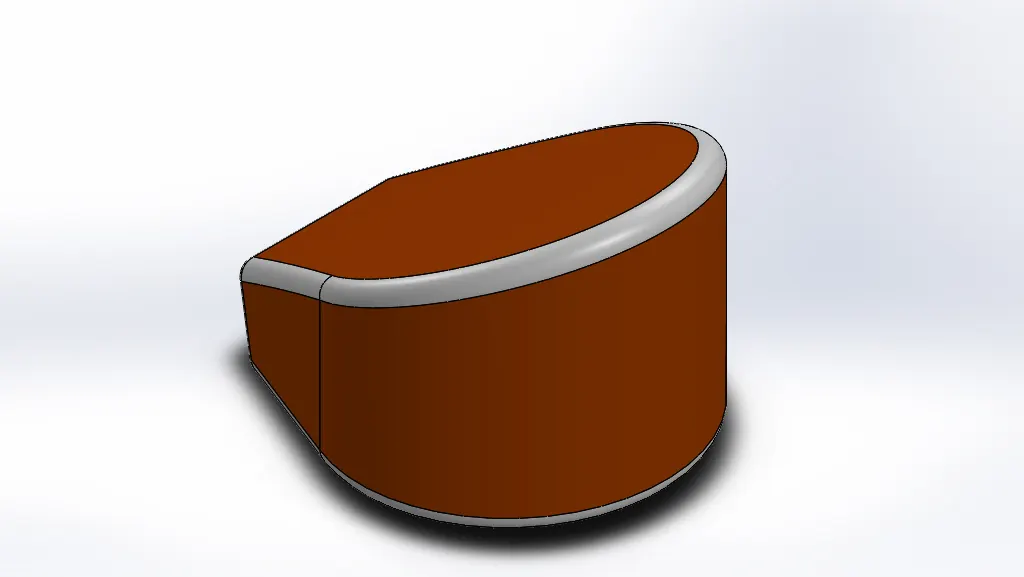
Oil tank:
Front view
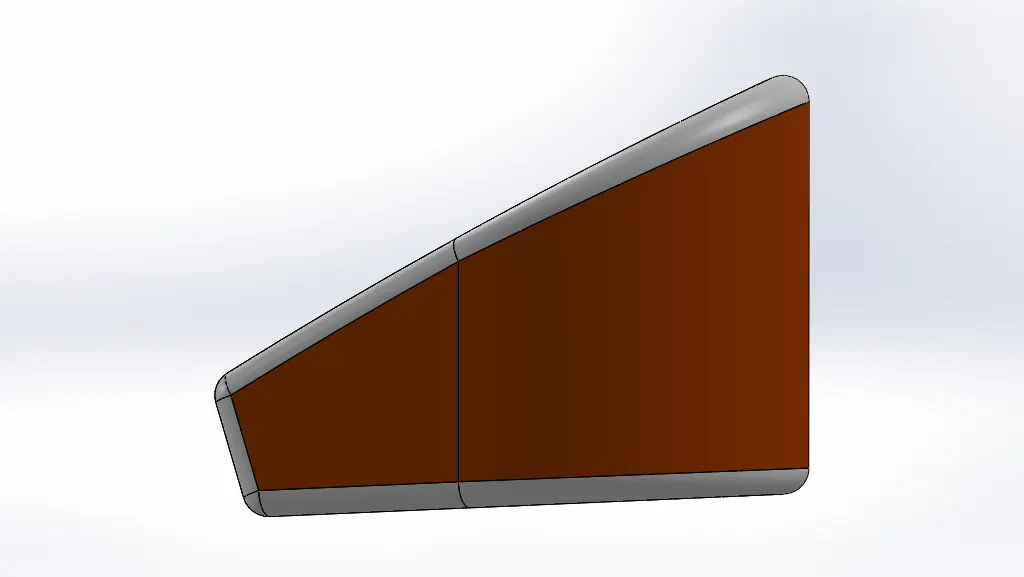
Side view
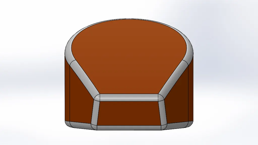
Isometric view
Tools & Features used:
Sketch: To create required sketches
Line: To drawing lines and construction lines
Spline: To draw curves through interpolation of points
Split: To separate or split solid bodies
Fillet: To convert sharp internal or external edges into smooth or round edges
Boss-Extrude: To obtain 3d solid from 2d sketch
Combine: To combine or merge solid bodies
Shell: To convert solid bodies into shells
Smart dimensions: To add or edit dimensions of sketches
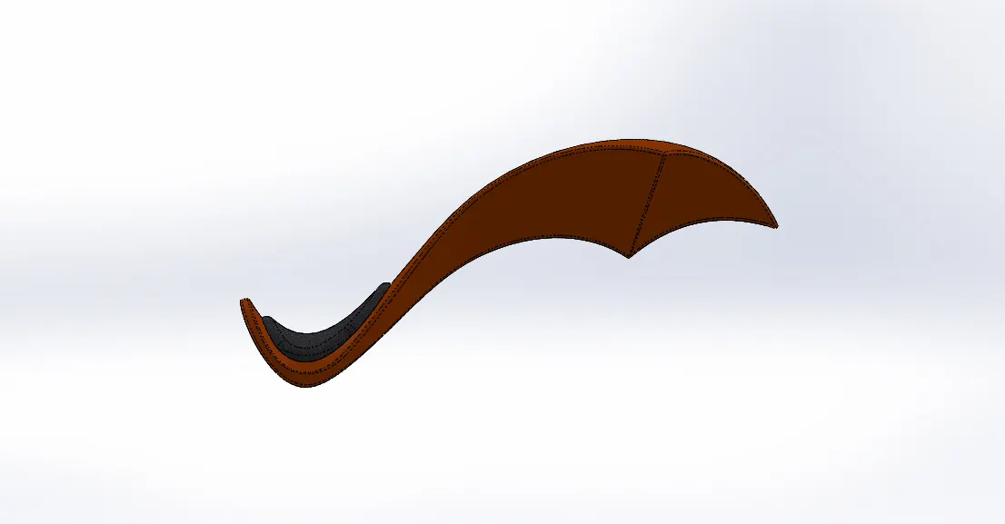
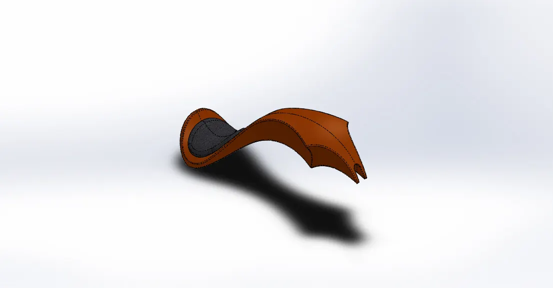
Gas tank:
Front view
Side view
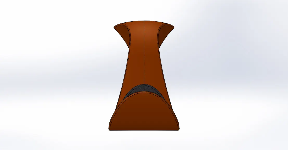
Isometric view
Tools & Features used:
Sketch picture: To insert pictures for reference
Sketch: To create required sketches
Line: To drawing lines and construction lines
Spline: To draw curves through interpolation of points
Split: To separate or split solid bodies
Fillet: To convert sharp internal or external edges into smooth or round edges
Boss-Extrude: To obtain 3d solid from 2d sketch
Reference plane: To construct a reference plane if existed references are not suitable or far away
Surface-loft: To create surface along the profiles
Surface-knit: To combine adjacent non intersecting features
Surface-sweep: To sweep along the sketch to obtain surface
Boundary-surface: To create surface from closed profile
Cut-sweep: To cut the surface along the profile through sweep along the reference
Shell: To convert solid bodies into shells
Mirror: To mirror features or sketches along the selected reference
Smart dimensions: To add or edit dimensions of sketches
Front fork:
Front view
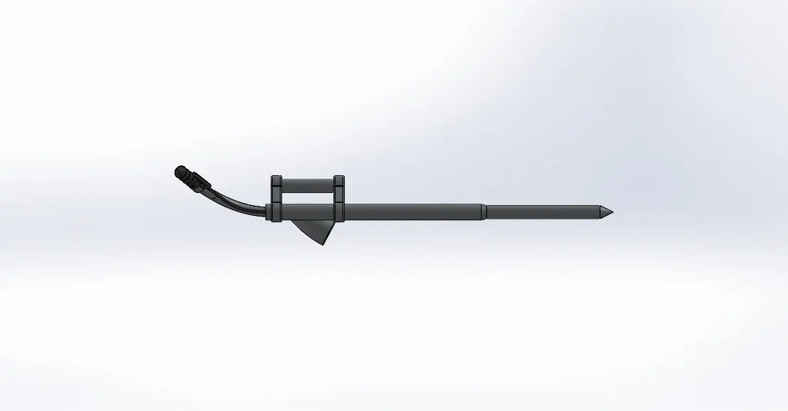
Side view
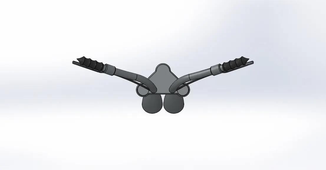
Isometric view
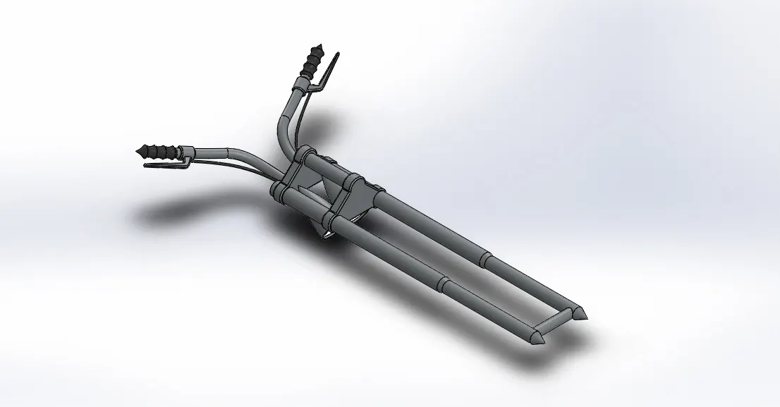
Tools & Features used:
Sketch: To create required sketches
Line: To drawing lines and construction lines
Circle: To draw circle
Arc: To draw arc
Spline: To draw curves through interpolation of points
Convert Entities: To convert edges or curves into lines
Intersection curve: To get an intersection curve obtained from projection of two curves
Boss-sweep: To obtain a solid body along the profile path
Boss-Extrude: To obtain 3d solid from 2d sketch
Boss-Revolve: To revolve 2d sketch along the reference to obtain solid body
Cut-Extrude: To subtract a solid portion from a solid using 2d sketch
Reference plane: To construct a reference plane if existed references are not suitable or far away
Mirror: To mirror features or sketches along the selected reference
Combine: To combine or merge solid bodies
Dome: To create dome surfaces on flat surfaces
Fillet: To convert sharp internal or external edges into smooth or round edges
Linear Pattern: To create a pattern of feature or body along a linear reference
Smart dimensions: To add or edit dimensions of sketches
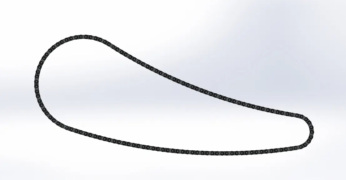
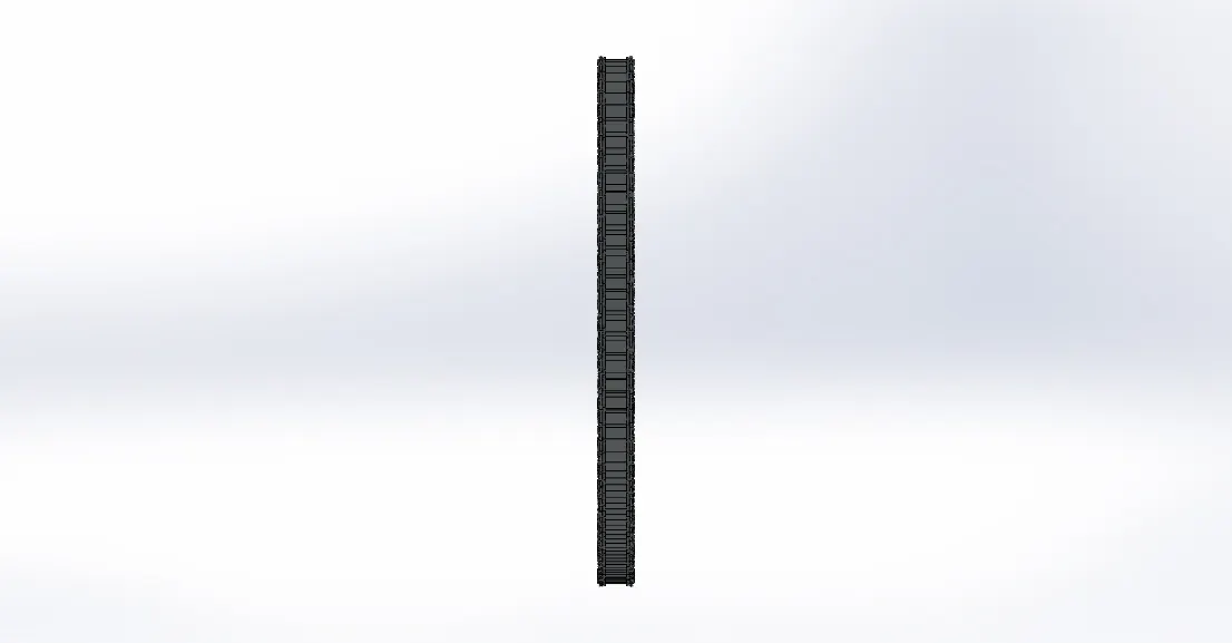
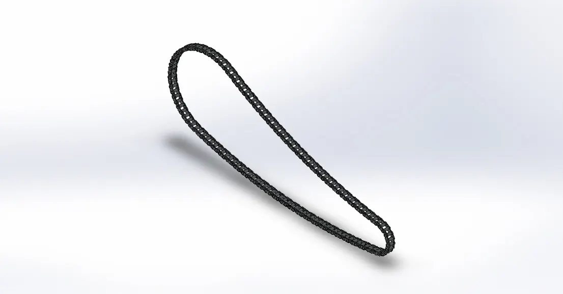
Chain part:
Front view
Side view
Isometric view
Tools & Features used:
Sketch: To create required sketches
Line: To drawing lines and construction lines
Circle: To draw circle
Arc: To draw arc
Spline: To draw curves through interpolation of points
Block: To create separate and save sketch from the existing sketch
Boss-Extrude: To obtain 3d solid from 2d sketch
Mirror: To mirror features or sketches along the selected reference
Combine: To combine or merge solid bodies
Fillet: To convert sharp internal or external edges into smooth or round edges
Curve Pattern: To create a pattern of feature or body along a curved reference
Smart dimensions: To add or edit dimensions of sketches
Pedal:
Front view
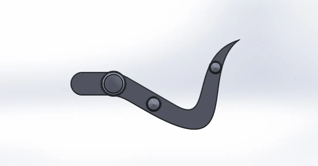
Side view
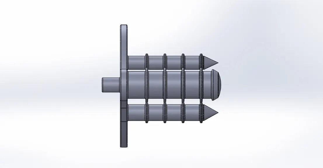
Isometric view
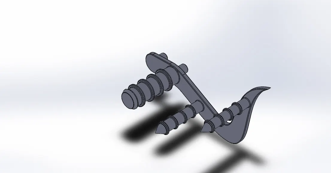
Tools & Features used:
Sketch: To create required sketches
Line: To drawing lines and construction lines
Circle: To draw circle
Arc: To draw arc
Spline: To draw curves through interpolation of points
Boss-Extrude: To obtain 3d solid from 2d sketch
Boss-Revolve: To revolve 2d sketch along the reference to obtain solid body
Combine: To combine or merge solid bodies
Dome: To create dome surfaces on flat surfaces
Fillet: To convert sharp internal or external edges into smooth or round edges
Chamfer: To convert sharp edges into bevel edges
Linear Pattern: To create a pattern of feature or body along a linear reference
Smart dimensions: To add or edit dimensions of sketches
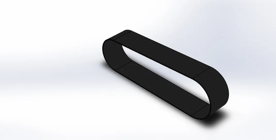
Transmission belt:
Front view
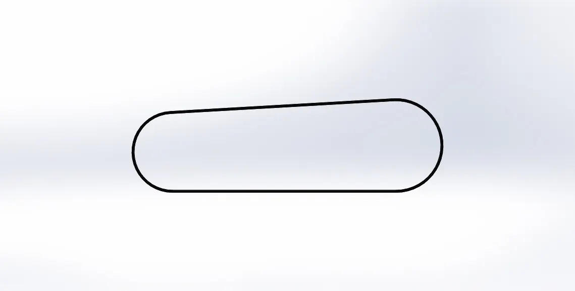
Side view
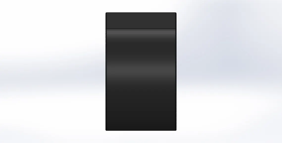
Isometric view
Tools & Features used:
Sketch: To create required sketches
Line: To drawing lines and construction lines
Arc: To draw arc
Boss-Extrude: To obtain 3d solid from 2d sketch
Fillet: To convert sharp internal or external edges into smooth or round edges
Smart dimensions: To add or edit dimensions of sketches
Kick stand:
Front view
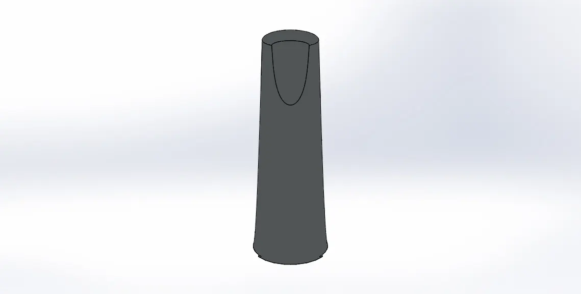
Side view
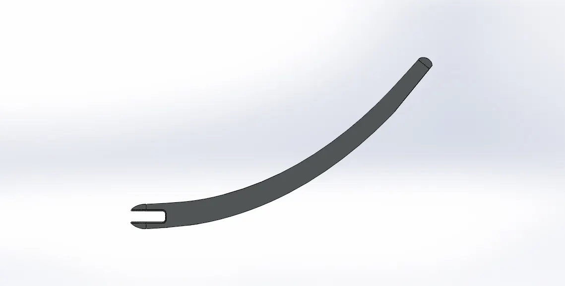
Isometric view
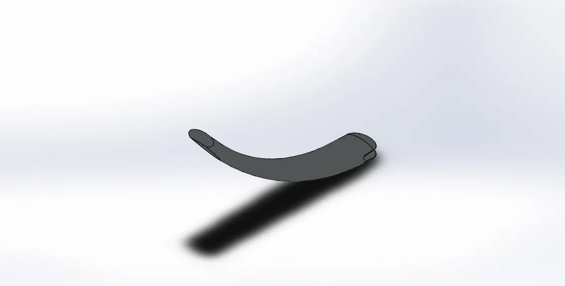
Tools & Features used:
Sketch: To create required sketches
Line: To drawing lines and construction lines
Arc: To draw arc
Boss-Extrude: To obtain 3d solid from 2d sketch
Dome: To create dome surfaces on flat surfaces
Cut-Extrude: To subtract a solid portion from a solid using 2d sketch
Loft: To create surface along the profiles
Split: To separate or split solid bodies
Fillet: To convert sharp internal or external edges into smooth or round edges
Smart dimensions: To add or edit dimensions of sketches
Assembly:
Front view
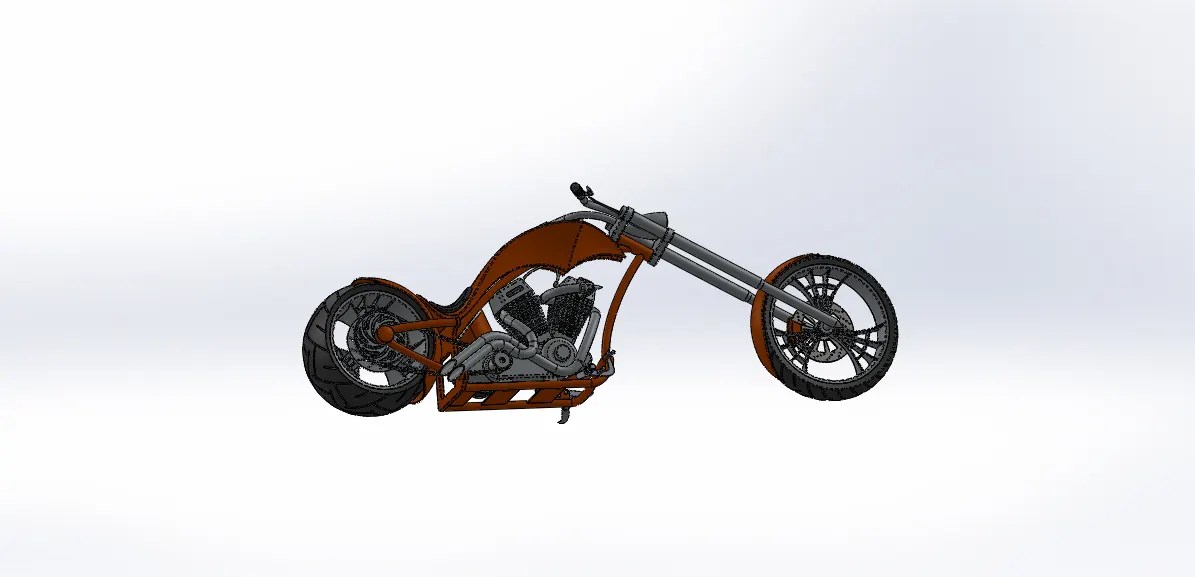
Side view
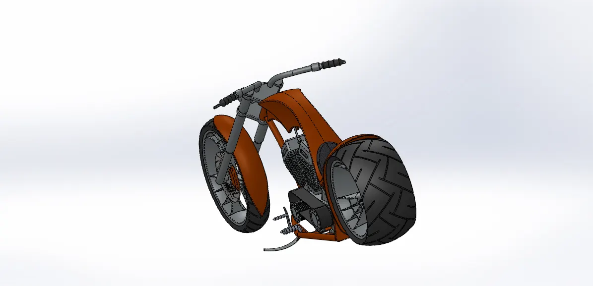
Isometric view
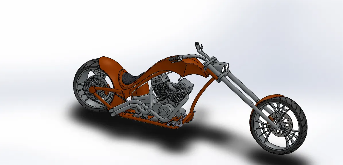
Tools & Features used:
Mates: To create constraints between surfaces
Rendering:
Front view
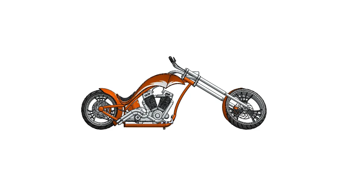
Side view
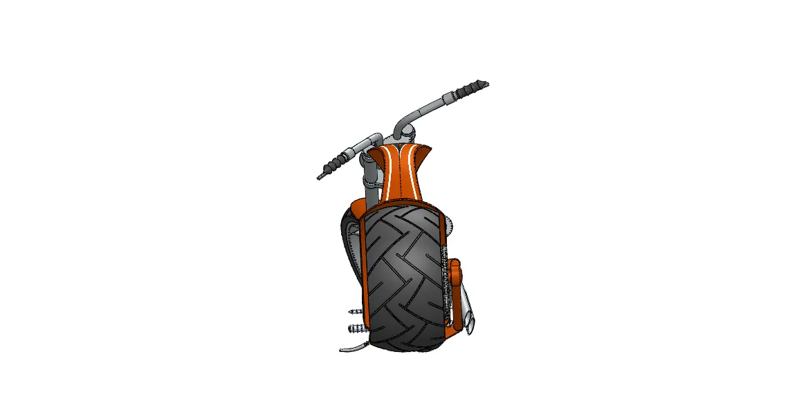
Isometric view
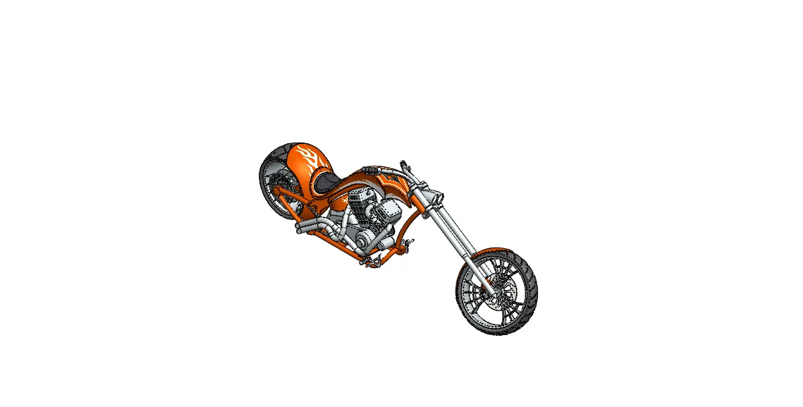
Camera view
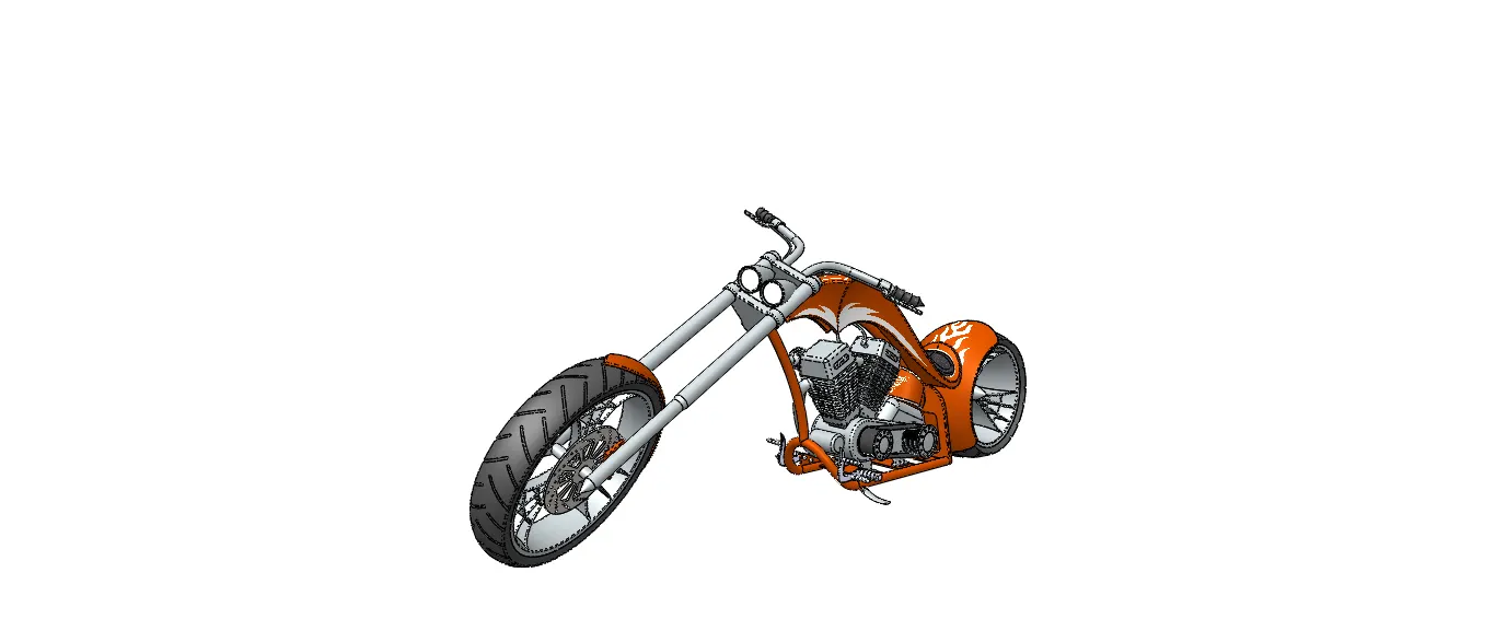
Top view
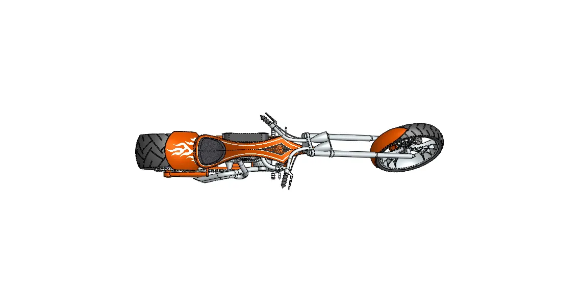
Rendered with Environment
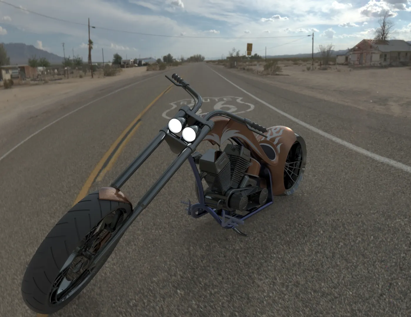
Tools & Features used:
Decals: Graphics or designs used on chopper bodies
lights and camera : To adjust lighting and camera angles
Render Preview: To preview the final render before rendering
Render: To render in required quality and sizes
Conclusion:
Thus the chopper model is modelled, assembled and rendered using solid works software
Link for Part files, assembly files and rendering files : Srikanth_Assembly_Chopper