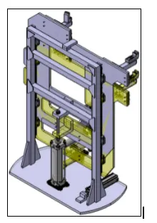
Week 3:- BiW Fixture Design Methodologies Challenges
1) What is Design Methodology?
The approach, process, or processes to be followed in creating a design are referred to as design methodology. Design methodology comprises a design tree in which the name of a specific component, assembly, or portion of an assembly is displayed in a specific order that is easily understood by everyone.
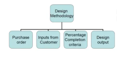
a)Purchase Order
It is basically a confirmation from the customer side, that we are ready to start the designing.
b)Inputs from Customer
Input from customers are the major inputs/suggestions that we receive from the customers, These inputs we have to study and analyze those inputs.
c)Percentage Completion Criteria
Percentage completion criteria is a time plan / schedule which we define for completion of design. So, when we are going to complete the in entire designing, then we're going to move on to simulation on all these subcategories would be considered in percentage completion criteria like a probability to when we can complete the entire fixture design.
d)Design Output
In BIW fixture design or any industry. We don't only just design a particular component and just give the CAD file to the customer, you have to give a lot of documents like 3d documents,2d documents, which is the detailing part, and as well as other factors as well like BOM (bill of material) and other documents as well about this particular component and their standards, all has to be submitted to the customer.
2. What are the inputs required from the customer to start designing a Fixture?
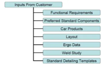
a) Functional Requirements
This basic functional requirement of the fixture which is to be designed are given here. The process which are involved in designing fixtures such as welding, gluing, riveting fastening are examples of functional requirements.
b) Preferred standard component
Preferred standard component are the standard components that the customer already have. And we have to design, according to the standard component itself. And this inputs actually saves a lot of time, money and efforts. So, if they have any component that we already have their standards, then we don't have to design those particular components.
c) Car products
Car products like 3d files, read files, geometrical tolerances of fixtures and PLP points are identified / designed in this step.
d) Layout
Layout is the arrangement and space of the entire assembly line which helps to understand the process and the flow of work.
e) Ergo Data
Ergo data involves manual operators and staff. Every company has different types of standards and aggregate ergo data. So, the particular inputs will be given by the customer. From the inputs we can design by considering safety, easy and fool proof designs
f) Weld Study
This involves the study of the particular gun that we are going to use for welding and where we are going to weld. Suppose if you're doing a spot welding what kind of spot welding, we are going to do number of welding to the particular component and all other details are studied here.
g) Standard Detailing Templates
Standard detailing template means every company has different types of standards, so they will give us detailing templates about how to detail the particular component and dimensions.
3) What is the input we get from "Car Products"?
GD&T, Part list, Cad Files of Automotive Parts, Clamp Plan, and Product Assembly Process Sheet are the main inputs we acquire from car products.
a)GD&T:
The geometrical dimensioning and tolerances of the specific pieces are provided in GD & T. Furthermore, information on Locating pins, rests, clamps, dumps, slide information for each station, and the sequence of clamp, dump, and slide stroke opening is provided.
We will learn how to locate pins in GD & T so that we can properly locate our pin units and clamp. How the complete component will rest, or how it will be clamped and dumb and slide information in each station sequencing and opening of clamp and slide Stroke
b) Part list:
The parts and assembly style are listed in the part list. For instance, the first assembly will be between the installation of a panel and the attachment of that panel. The hinge will be the following step. As a result, each assembly will have a unique portion. As a result, we'll need to create a variety of assembly parts. Part numbers and part names are listed in the part list. Every component has a unique name.
c) Cad Files of Car Parts:
CAD files of cad products means the 3d component that we required from all the Cad parts
d) Clamp Plan:
Clamp Plan is a very significant input that we obtain in the vehicle goods because it tells us where we may position those clamping units, which are the specific pin Units. We should never modify the position of a certain clamp or pin that is specified in these specifications. We can tweak our design a little bit here and there, but we shouldn't change the clamp or pin positions in the input design data.
e) Product Assembly Process Sheet:
In the Product Assembly Process Sheet we find what kind of products we are going to assemble in that particular component or the particular Unit. The sequence of the assembly and
stages of the assembly are properly mapped in this sheet.
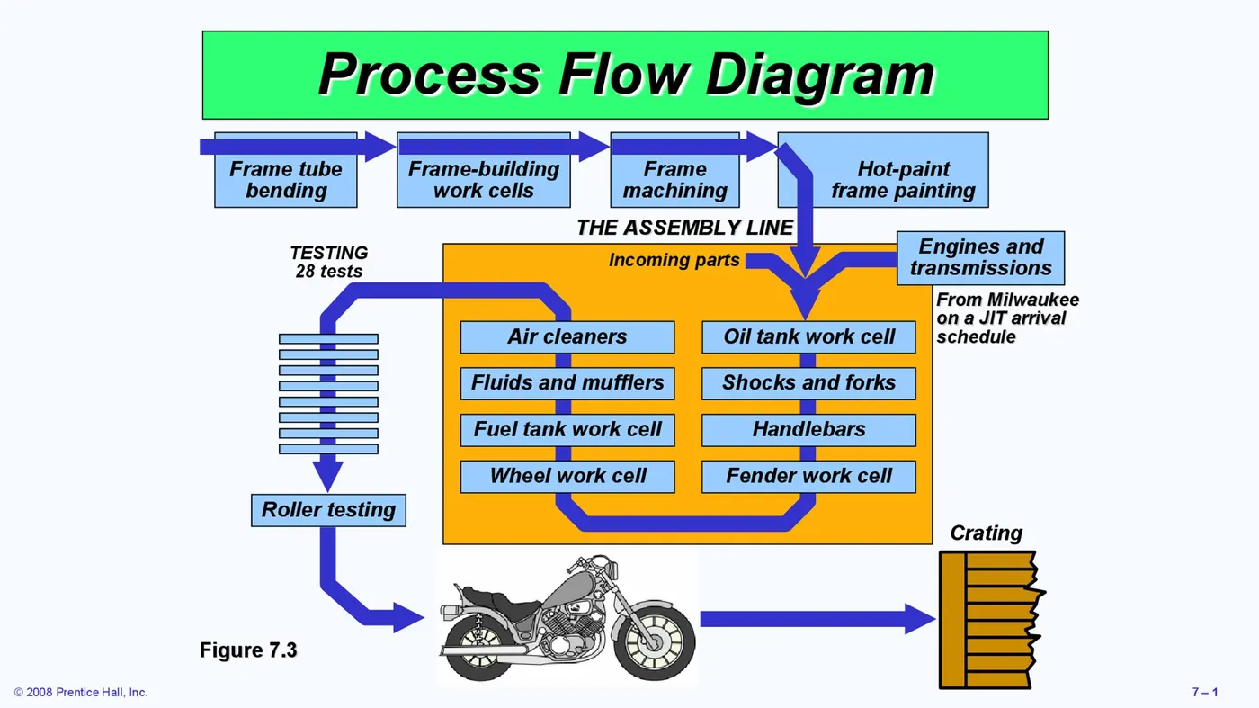
4)What is the Clamp plan?
A clamp is a fixture's force-actuating device. The clamps' forces keep a part firmly in place in the fixture in the face of all external influences. For invariant location, clamping surfaces are subjected to clamping forces.
The part's clamping plan is the blueprint that specifies where the clamp will be placed during the operation to guarantee that the assembly's geometry is maintained. Without the customer's approval, we are unable to change the clamp plan. We need to create a fixture that doesn't require any changes to the clamp layout. The clamp plan contains information on pin locations, rest, clamps, dumps, and the clamp plan's coordinates, which aids the design team in assembling and working with the fixture.
5)What is the purpose of a Layout?
Layout is the physical arrangement of machines, processing equipment and service departments to achieve greatest co-ordination and efficiency of 4 M’s (Men, Materials, Machines and Methods) in a plant., either existing or in plans of industrial facilities.
Plant layout is a floor plan for determining and arranging the designed machinery and equipment of a plant in the best suitable place which allows the easy flow of material, at the lesser
cost and time which improves efficiency of the work place.
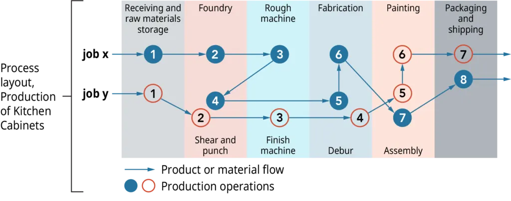
the above figure depicts the process layout of production of kitchen layouts
6)What is Ergo data?
Ergonomics is the engineering and design of products, processes, and systems using psychological and physiological concepts. Human factors aims to reduce human error, increase productivity, and improve safety and comfort by focusing on the interaction between humans and the object of concern.
Ergonomic data is examined in order to discover and quantify ergonomics working postures that contributed to the serious development of muscle skeletal injuries, as well as possible contributory factors.
Take, for example, the final assembly of an automobile, which entails a number of steps. Some assembly activities require manual work. All processes must be continuously improved in order to minimise costs and increase productivity. To complete the assembly operation, the workers adopt diverse postures, exert force, and work constantly in cycle time. So, using all of the ergo data, the work place layout and fixtures will be created to maximise manual labour productivity while also ensuring worker safety.
7) What do you understand by Weld study?
weld study is a study of the particular gun that we are going to use for welding and where we are going to weld. So, if we doing a spot welding what kind of spot welding, we are going to do
number of welding to the particular component. Weld study includes Weld Gun Details, Weld matrix and weld points and Geo weld points and Re-spot Weld Points.
a)Weld Gun Details:
This involves the study of the weld gun which includes weld gun details such as how to use where to use etc.
b)Weld matrix and weld points:
Weld points are the points where the welding is to be done and at which point i.e. at which coordinate.
c) Geo weld points and Re-spot Weld Points:
The data of weld matrix and weld points will be given to you in the form of spears i.e. Green and red spheres. Geo spots are Red in Color and Re spots are Green in color. All the red spheres
are going to happen in geostationary. In the res-pot station where the green welding is going to happen. This happens when one component is to be assembled this particular component in
one station and in the other station, the other component is to be attached.
8) What are the criteria for percentage completion in the designing stage?
Percentage completion criteria is a time plan / schedule which we define for completion of design. So, when we are going to complete the in entire designing, then we're going to move on
to simulation on all these subcategories would be considered in percentage completion criteria like a probability to when we can complete the entire fixture design. The percentage
completion criteria is categorized as follows
- 0-25% Input and concept design
- 25-40% Concept approval and simulation
- 40-85% Design freezing and detailing
- 85-100% Check and Final dispatch
Input and concept designing
In this they given four days to design the fixtures that means we have to complete 25% of the task within four days.
Concept approval and simulation
The concept of design is approved here, and the simulation check is done here, which is 25 to 40% of your design is complete in Concept approval and simulation.
Design freezing and detailing
In this process the design gets finalized. And the detailing is going to start again. Once the detailing is finished, and the design is also feezed that means you have completed at least 40 to
85% of task.
Check and Final dispatch
In this stage this is final stage, Here checking the quality check usage and the final dispatch, which is the output that we are going to give to the customer, which is from 85 to 100%.
9) Brief about "Output" in design?
In BIW fixture design or any industry. We don't only just design a particular component and just give the CAD file to the customer. We have to submit a lot of documents like 3d
documents, 2d documents which details the part and other factors as well, like bill of material and other documents and the standards followed etc.
To be specific outputs in design should
a) meet the input requirements for design and development,
b) provide appropriate information for purchasing, production, and for service provision
c) contain or reference product acceptance criteria, and
d) specify the characteristics of the product that are essential for its safe and proper use.
The basic output are 3D models and the 2D drawing of the tools
1.Unitized Tools
In the unitized tools testing requires two types of drawing sheet, which is one key sheet and layout sheet. These sheets are an index of units and placements on the tool base. Layout
sheet is a detailed drawing of that particular tool which shows details of components and how and where it is to be placed. Key sheet shows the placement and the location of that particular
tool on the tool base where exactly the tool is placed. And what is his exact position in a particular place.
2.Non-Unitized Tools
Non unitized tools are basically tools like Stands and tool changers where you don't need key sheet. Tools that can stand alone and can be detailed completely on a layout. We can use to
layout sheet and complete the entire documentation of the particular component.
10) What do you understand by structuring a design tree? How does it reduce errors during the design process?
Structuring a design tree implies to a process where all the assemblies & parts are named in a specific standard. Different customers have their different set of standards to structure a
design tree. It is an important process which helps us to identify a specific part or assembly as to which project, tool or unit, it belongs to. This helps us to avoid the errors during design study,
manufacturing, assembly, inspection etc.
If the parts or assemblies are not properly or the design tree is not structured properly, it will create confusion to understand the design & may create major possibilities of making an
error. Naming of a fixture or a unit or a part, gives the information as to which project or zone or assembly do, they belong. It can help us to identify the quantity of items of same type or
different types are being used in assembly.
The basic structure followed in structuring tree design was under the product there are main assemblies, Sub-assemblies, Child part, Standard parts etc. these all parts are provided with
specific no, Zone etc. to identify easily.
- The upper portion of tree represents the parts that are to be designed or manufactured
- The lower portion of tree represents the standard parts
11) What are Units? Mention 5 types of units.
A unit is a device that performs a certain job, usually as part of a larger mechanism. The BIW fixtures are made up of many units that are designed to serve various purposes.
There are two types of tools in units: unitized and non-unitized.
The unit performs specific tasks such as resting the panel, clamping the part, and locating the part, among others. The devices are designed to find and fasten the automobile panel to its designated position in the fixture while the operation is in progress, according to the 3-2-1 concept of fixture design.
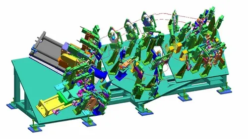
The basic units in BIW fixture design are as follows:
a) Fixed pin unit:
It is non movable locating unit used for proper location of the part and arrests the movements as well
b) Retract pin unit:
It is movable locating unit which have retracting mechanism. Which creates ease in assembling two components placed in different directions
c) Rough locator unit:
It roughly guides the operator for locating the part on the fixture.
d) Rest unit:
The panel is rest on this unit.
e) Base unit:
It is the unit on which all other units are mounted.
12) Describe Fixed Pin units & their purpose?
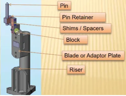
Riser, blade, block, shims or spacer, pin retainer, and pin make up a fixed pin unit. The standard element that is utilised to raise the height of the while unit is the riser. Blades are plates that are attached to the riser. Other components, such as the cylinder and arms, are mounted to the blade. Shims are little parts having thicknesses of 0.1mm, 0.2mm, 0.5mm, and so on. These will adjust for the stack up tolerance, which is reflected in the Mylars, which hold the panels in place. Shims are used to compensate for translational motions in fixed pins. The pin retainer will hold the pin and the locating pin in place, preventing the car panel from moving.
Purpose of fixed pin unit:
- Fixed pin unit is a unit designed to locate the car panel using pin.
- The fixed pin unit is the part of the 3-2-1 principle. It restricts 6 degrees of freedom of the car panel.
- It is necessary to have 2 pins to locate car panel. one pin must arrest 4 way (4 translational) & other must arrest 2 way (2 rotational) of a car panel
13) What are the different parts of a fixed unit?
Fixed unit consists of fallowing parts
- Riser
- Blade
- Block
- Shims
- Pin Retainer
- Locating Pin

Riser: Riser is the standard part which is used to rise up the height of the whole unit. Generally, risers are either made of plate fabrication or plate and tube welding together or from single
gas cut plate.
Blades: These are plates mounted on the riser. Other parts like cylinder, arms etc. are mounted on the blade.
Block: Blocks can be machined to any desired fixture component. Because they come as a blank block, the possibilities are endless. Adding new tap holes or grinding down to your
specifications are quick and simple.
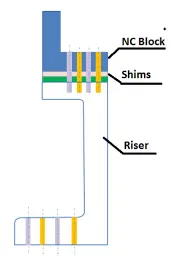
Shims: These are the small part which comes with the thickness of 0.1mm, 0.2mm, 0.5mm etc. These will compensate the stack up tolerance which reflects at the panel holding part
called Mylars. We give tolerance to all the parts of the fixture. Due to this tolerance the Mylars will either lift up or goes down from its defined position. If the Mylars goes down from the
defined height it will make impression or dent on the panel. If the Mylars lift up then there will be a distortion due to welding stress. To adjust the Mylars At its defined position we use shims
so the panel won't deformed & also don’t get any impression on it.
Pin retainer: It will support the pin
Locating Pin: Typically, locating pins are used to position a work item in a controlled, fine-tolerance manner. For example, locating pins may be the ideal answer for a pallet that is moved along one axis and the driving mechanism is not exact and stable enough to place it in a position that is accurate enough to conduct a specific process. The Diamond Shape is an important characteristic that aids in the reduction of machining errors and the smoother operation of the locating process. When two round head pins are inserted on one plate, the spacing between two mounting holes must be quite accurate, and even then, the work piece will not be as easily positioned on the base as if a diamond shape pin were used.
14) What is the purpose of making a Rest unit & describe its parts?
Using NC blocks/Mylar/Rest, the rest units are meant to rest/support the automobile panel. It's the easiest unit to design because it has the fewest pieces. The rest unit is integrated with other units to minimise the overall project cost due to its simplicity. It can be used in conjunction with a clamp device to both clamp and rest the automobile panel. It can be used in conjunction with a locating equipment to both locate and rest the automobile panel. Also, to save money, the finding, clamping, and resting units might be combined into one unit.
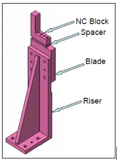
The major parts in rest unit are
a) Riser: Riser is the standard part which is used to rise up the height of the while unit.
b) Blades: These are plates mounted on the riser. Other parts like cylinder, arms etc. are mounted on the blade.
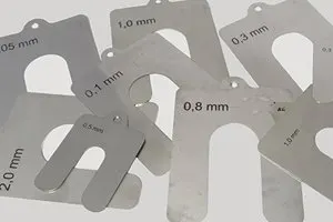
c) Shims: These are the small part which comes with the thickness of 0.1mm, 0.2mm, 0.5mm etc. These will compensate the stack up tolerance which reflects at the panel holding part
called Mylars. Shims are used in one in direction in rest unit which is up & down because it requires adjustment in height only
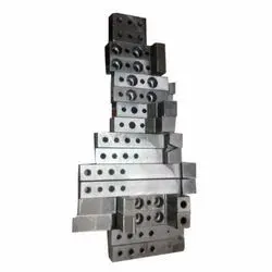
d) Mylars: Mylars is the component which holds the panel while operation. These are placed from top side & from bottom side also. The top side Mylars called as Clamping Mylars & the
bottom side Mylars called as Resting Mylars. Every clamping Mylars have resting Mylars. It don’t allow deformation of the part due to welding stresses.
15) What are the basic fundamentals to design a Sensor unit?
A sensor is an electronic device that detects or measures a physical property and records, indicates, or responds to it in some way. The term "sensor unit" refers to a device that uses electrical sensors to detect the presence of a car panel. The signal from the sensors is sent to the PLC, which then executes the following operation.
There are different types of sensors such as proximity sensor, laser sensor, photo electric sensor, infrared sensor etc
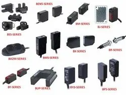
Each and every loose panel being welded in a tool should be detected. So, in that particular panel, we're going to assemble every single panel.
If there are nine separate panels to assemble in one panel, for example. Every single one of those panels should be equipped with a sensor. Depending on the size of the panel, one or two sensors should be used to detect it. If a component is extremely small, only one sensor is required to detect it. If the panel is quite large.To sense their individual panel, we'll utilise two sensors pointing in opposite directions. As a result, each sensor should be changeable in three directions (upward, downward, right, and left).
16) What is a Rough locator unit & what are the basic fundamentals to consider while designing it?
A rough locator is a device that instructs the operator on where to place the automobile panel on the pins. A rough locator might be either a standard or a custom item. It's also known as a foolproofing procedure. Because the part cannot be loaded in the proper location due to the rough locator. Because the rough locators are placed according to the angle of each panel, the part can only be loaded in a specific direction and orientation.
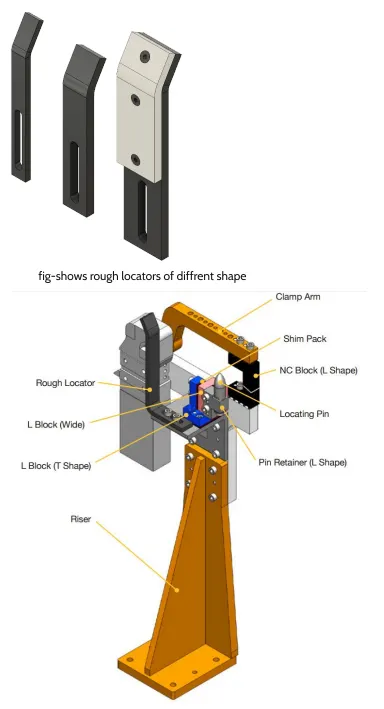
Fundamentals of rough locator design
- Rough locator should be placed at the edges of the car panel, which it has to guide.
- They should be placed in the same angle of the car part edge with a minimum distance of 2-5 mm from the edge of the car part.
- It should guide the panel in pin arresting direction.
- Rough locator should start guiding the panel before 10 to 15mm to the start of the pin engagement. Rough locator should be designed with entry angle for the car panel. Generally, it ranges between 30-45 degree.
- Rough locator should be designed with two slots to mount the easy adjustments.
- The slots should be in the direction of car part guiding.
17) What is a Base unit and describe it's parts?
A base unit is the unit on which all other units, such as the clamp unit, pin unit, rest unit, and other elements required for a tool, such as the pneumatic valve box and trunking cable path, are installed.
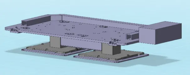
Base unit’s parts are as follows
a) Floor plate: It is the plate which join the fixture to the floor by using some nut bolts. This plate surface is machined for maintaining the horizontal position of the fixture.
b) Weld bars & pedestal: Pedestal is the base or support on which the fixture is mounted.
c) Eyebolt: An eye bolt is a bolt with a loop at one end. They are used to firmly attach a securing eye to a structure, so that ropes or cables may then be tied to it. Machinery eye bolts are fully
threaded and may have a collar, making them suitable for use with angular loads up to 45°. Eye bolts without a shoulder should not be used for angular loads.
d) Measuring hole cover: The base plate has some drills to mount various units like clamp, rest, pin etc. & every drill have some coordinates to define the exact location of the hole. Due to
irregular shape of the car panel the drilled holes coordinates are not like 110.0, 150.0 But it like 110.62,150.84. The measuring hole is drilled over the base plate which having exact
coordinates so that all other holes can take reference from it. The measuring hole no. depends on the size of base plate. These holes are covered by using some plate to protect against dust,
damage etc.
e) Valve box & trunking channel: The valve box is the box which includes different solenoid valves. The pneumatic fixtures work on air pressure provided to it. So, the arrangement of air
pressure inlet & outlet is done within this valve box. The trunking channel includes all the pressure inlet cables going to the pneumatic parts of the fixture & protects them from damaging
while operation is in process.
f) Base plate: Base plate is the heavy plate of large thickness because it carries all the weight of the mounted parts. So, it must be able to bear the load. Base plate is machined to maintain
the parallelism within the tolerance. It also consists some drilled holes to mount the different units over it.
18) What is a Dump Unit and what are its functions?
Dump unit is the complex unit to design due to space constrains there is less space available & have to adjust all the parts in available space. It consists of dump cylinder to perform the
operation of clamping & unclamping car panel.
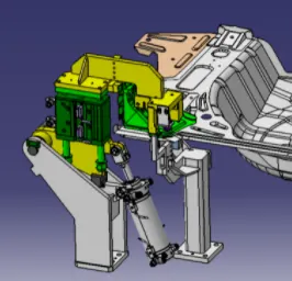
Functions of Dump Unit:
If you have a specific limitation that prevents you from assembling normally, the dump unit comes into play. It has a dumb cylinder with two positions: open and closed. It also has a Clamp Cylinder Unit. That is why they are so intricate and well-designed. You can use this dampener to limit your components if you have any geometrical constraints.
19) What is a Slide unit? Mention where Slide units are commonly used.
Slide units are positioning units that are used to place the fixture, weld gun, and other units, as well as robots, in the proper position for subsequent operations. The slide unit comprises of a sliding cylinder with one open and one closed state that must guide rails in the direction that the entire panel will move. Sensors to determine if the complete component has arrived here or not, and a position locking mechanism that locks the position at that specific moment without allowing the entire plate to move. The mobility at the ends is restricted by stopper blocks. These are widely used in automotive assembly to operate on a single unit with multiple sized components.