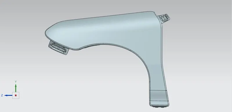
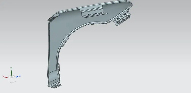
Fender Design Challenge
FENDER:
A fender is the curved portion of the car’s body that sits over and houses the wheels. The purpose of a fender is to prevent mud, pebbles, and other road debris from being flung about by the tyres In other terms, the fender is a wheel casing that keeps road debris confined. If there was nothing covering the wheels, the revolving tyres would kick up all kinds of debris. The fender not only protects your automobile from road debris, but it also keeps this debris from being flung up at other vehicles on the road.
TYPES OF FENDERS:
There are two types of fenders
- Full Bumper type
- Half Bumper type
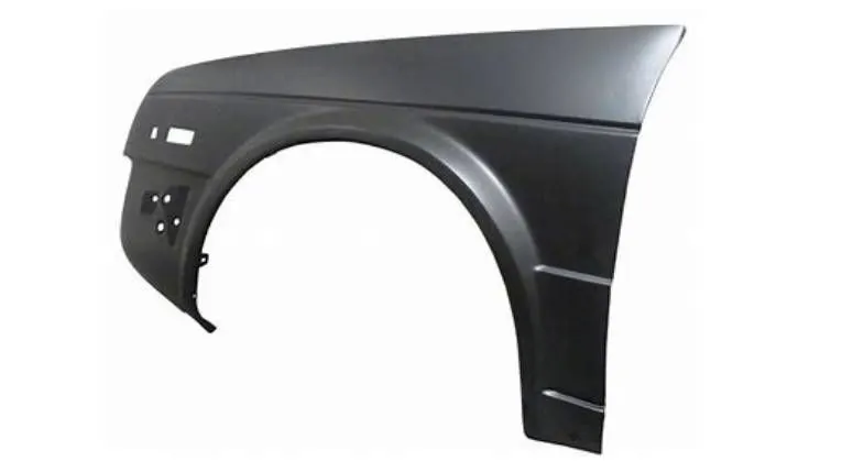
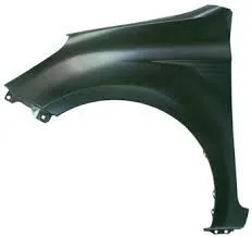
FULL BUMPER TYPE FENDER HALF BUMPER TYPE FENDER
- As shown in figure in full bumper type more blank is used for manufacturing there increasing weight and steel waste for producing it, where as for half bumper type fender sheet metal is optimized for blanking by reducing steel wastage and by adding plastic components weight reduction is attained. This improves overall performance of the automobile.
MOUNTING REGION ON FENDER:
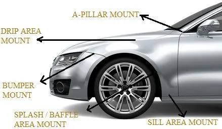
There are 5 mounting regions on the fender. They are
- A-pillar mounting
- Drip mounting
- Bumper mounting
- Sill mounting
- splash/ baffle mounting.
MANUFACTURING METHODS OF FENDER:
- Step 1: open straight snips plate: first select applicable cold coiling specification, cold coiling is opened flat; Then according to production material specification, will open cold coiling after flat and be cut into into the iron plate of corresponding size; Finally the iron plate after shear is cleaned to iron filings.
- Step 2: oil pressure, punch press: first iron plate is extended, Secondly to its trimming and punching. Then to its flanging and shaping, Finally after shaping completes, then carry out one-off hole-piercing, Completed the making of lappet plate body.
- Step 3: smallclothes of processing lappet: first iron plate is stamped out to required outline blank (blanking); Then to completing the further moulding of iron plate of outline blank, Finally it is carried out to punching.
- Step 4: panel beating assembly welding: first smallclothes are carried out to spot welding M6 nut; Then part point is welded on lappet; Finally lappet body and smallclothes are carried out to sanding thorn and ending.
- Step 5: All the plastic parts are produced by injection moulding.
DESIGN OF FENDER:
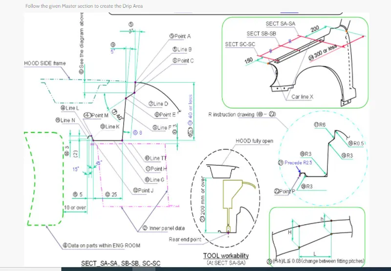
Fender is designed from above given master section data
DESIGN OF DRIP MOUNTING:
- While designing drip area mounting parameters should be considered i.e, 300 mm or less from A pillar region.
- All the other fitments assembly( wiper motor, head lamps, indicators, engine compartment,etc.,) considerations should be taken into account while designing the mounting postion along the length.
- While providing the angular dimensions for mounting care should be taken that mounting bolts are properly hidden from normal viewing line.
- Ribs should be provided for improving the strenth of the mount.
- Flat surface should be maintaned at the contact patch of the mount.
- Draft angle should be considered for designing and contact patch around the hole should be atleast 5 mm.
- At the extreme edge of the mount blend is performed to avoid vibrations and spring back effect.
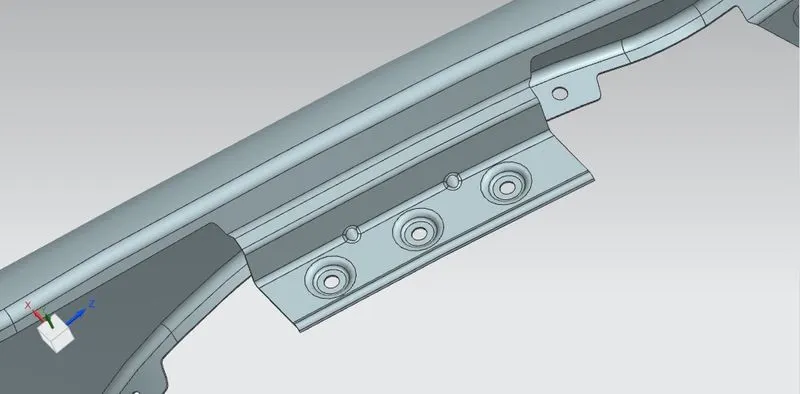
DESIGN OF SILL MOUNTING:
- Sill is present at the bottom of the fender that connects car floor and the body.
- At the mount flat surface should be maintained.
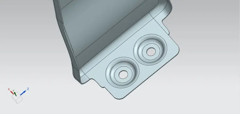
DESIGN OF BUMPER MOUNTING:
- It connects the fender with the bumper of the automobile with the help of fastners.
- At the mounting the surface should be maintained flat.
- Based of the design darts should be provided to inculcate the strength.
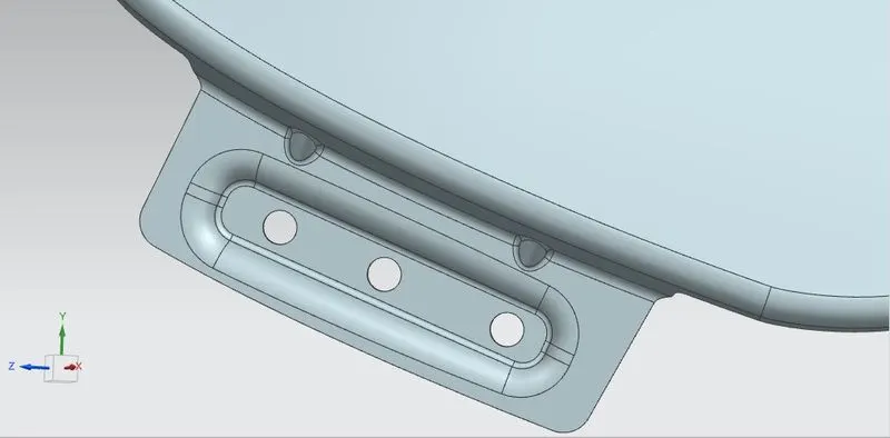
DESIGN OF A-PILLAR MOUNTING:
- It connect fender to the A- pillar of the automobile which connects to the roof.
- flat surface is maintained at the mounting.
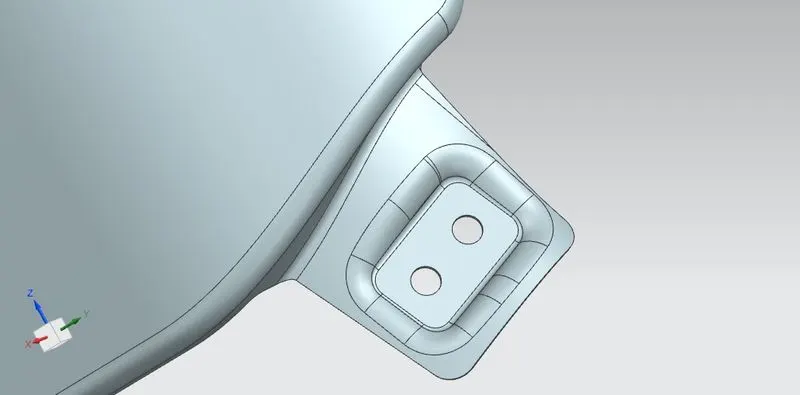
DESIGN OF BAFFLE MOUNTING:
- Baffle mountings connects the fender and baffle/splash at inner region which protects the automobile as well as pedestrians from chip out debris on the road when the automobile in motion. Wheel arc is taken into consideration for pedestrian safety as per the regulations.
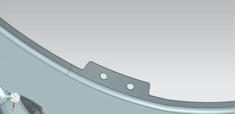
By considering all the above parameters fender is designed in the NX CAD software.
FINAL OUTPUT DESIGN OF FENDER: