Week 3:- BiW Fixture Design Methodologies Challenges
1) What is Design Methodology?
Purchase Order: Our design process commences upon receipt of a purchase order from the customer, serving as the signal to initiate the design of the specific fixture.
Inputs from Customer: Before embarking on the actual design phase, we gather requirements or specifications for the fixture from the customer. Therefore, our design considers all customer-provided details.
Percentage Completion Criteria: To ensure timely completion of the design, we establish a schedule known as the Percentage Completion Criteria. This schedule outlines all design-related activities and the time needed to accomplish each task, such as conceptual design, finalizing the design, and creating 2D representations of all fixture units.
Design Output: The design output encompasses various data including 3D and 2D documents, VMC IGS files, STEP files, gas-cut or laser-cut files in DWG format, and BOM (Bill of Materials), among others. We must provide these data to our customers as part of the design output.
2)What are the inputs required from the customer to start designing a Fixture?
Customer Inputs:
1. Functional Requirements:
Functional requirements are fundamental in defining the fixture's purpose, whether it's for welding, hemming, checking fixtures, or storage racks. These requirements dictate the design considerations that will be implemented.
2. Preferred Standard Components:
Every company adheres to certain preferred standards, which may vary depending on the company. These standards dictate the parts that can be integrated into our designs, saving both time and money on the project. Examples include ABB, NAAMS, TUNKERS, ZUTRAN, DESTACO, and standard components like risers, L blocks, retainers, cylinders, clamps, switches, and sensors.
3. Car Products:
This category encompasses several inputs from the customer:
A) GD&T (Geometric Dimensioning & Tolerancing): Provides information on locating pins, rests, clamps, dumps, and slides at each station.
B) Part List: A comprehensive list of parts to be assembled in the fixture.
C) CAD Files of Parts: 3D model files of the car parts designed using modeling software.
D) Clamp Plan: Essential input detailing the clamping plan during operations, including pin locations, rests, clamps, dumps, etc.
E) Product Assembly Process Sheet: Detailed process information from the inception to the completion of the part assembly.
4. Layout:
The layout provides information on the flow of parts, station pitch, robot station, tool changer, tip dressers, platform height, and sub-assembly links.
5. Ergo Data:
This pertains to the study of human behavior and movements during assembly work.
6. Weld Study:
A study focusing on the weld gun used for operations, considering factors such as part size and thickness.
7. Standard Detailing Templates:
Each customer has their standards for detailing, including templates used for 2D drawing and detailing.
3)What is the input we get from "Car Products"?
The input received from car products includes:
1. Geometric Dimensioning and Tolerancing (GD&T):
GD&T provides detailed information about the part for which the fixture needs to be designed. It includes specifics such as locating pin positions, the sequence for opening clamps, rest positions, and dump and slide stroke details.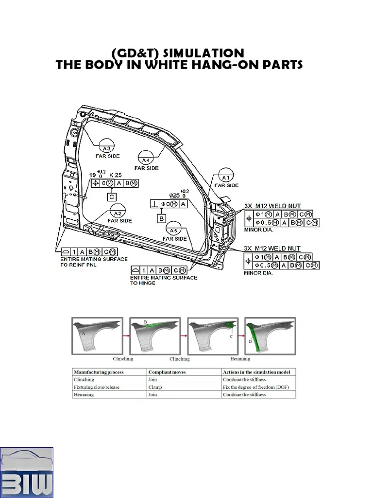
2. Parts List:
The parts list offers comprehensive information about the components involved in the fixture. It includes details like part names, part numbers, part thickness, and quantities required.
3. CAD Files:
CA files of the part provide crucial information such as the 3D model and design analysis results. This data is invaluable as it serves as a starting point for designing the fixture.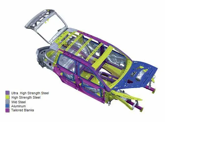
4. Clamp Plan:
The clamp plan is vital as it outlines the positions of clamps, pins, dumps, rests, etc. It's essential to adhere to the clamp positions unless approved by the customer.
5. Product Assembly Process Sheets:
These sheets detail the products to be assembled for a particular unit or component. They also provide the sequence of assembly steps, offering valuable insights into the assembly process.
4)What is the Clamp plan?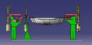
A clamp serves as a mechanism to secure the workpiece in place during operations, functioning as a force actuator within the fixture.
The clamp plan, a critical input from the customer, furnishes details regarding the placement of clamps to ensure the proper geometry of the workpiece is maintained throughout the operation. It specifies the locations of pins, rests, clamps, dumps, etc., and often includes coordinates for direct integration into the fixture design process.
It's imperative to note that alterations to the clamp plan provided by the customer are not permissible without consultation. Any proposed changes must be communicated to the customer for approval before implementation.
5)What is the purpose of a Layout?
The layout refers to the optimal arrangement of machines, processing equipment, and service departments within a plant to maximize the efficiency of the 4 Ms: men, material, machine, and method.
It presents a detailed floor plan illustrating the placement of machines, positions of robots, storage racks, and other essential elements. Additionally, it outlines the reachability of robots to fixtures, known as the swept area of the robot.
Moreover, the layout offers insights into the flow of parts, station pitch, robot stations, tool changers, tip dressers, and the sequence for loading and unloading operations. It serves as a blueprint for organizing resources and processes to enhance overall operational efficiency.
6)What is Ergo data?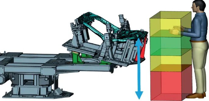
Ergonomics is the application of psychological and physiological principles to the engineering and design of products, processes, and systems. It aims to reduce human errors, increase productivity, and enhance safety and comfort, with a specific focus on the interaction between humans and the objects of interest.
During any operation, workers or operators assume various postures, exert force and work continuously within a cycle time to perform specific tasks. This can lead to a high level of strain on the operators. To mitigate this, ergonomic principles are applied in every operation where human-machine interaction occurs.
Ergo data provides human factors engineering data regarding the interaction between the operator and their working environment. It offers several benefits, including improved working conditions, reduced physical workload, better work postures, and decreased effort required for certain movements.
7)What do you understand by Weld's study?
Welding is a crucial process extensively employed in the automobile industry for joining parts together. Consequently, a welding fixture is imperative to ensure the part's geometry remains unchanged during welding.
A weld study encompasses an examination of the weld gun, weld matrix, weld points, geo spot, and respot weld points. The weld gun study provides insights into the type of weld, temperature, current type, approach of the gun, and other relevant parameters. Meanwhile, the weld matrix and weld points furnish precise information on where the welding operations will occur.
Typically, there are two welding stations: geo spots and respots. Geo spots involve the initial round of welding operations, followed by respots conducted at locations where welding was not possible during the geospot station.
8)What are the criteria for percentage completion in the designing stage? Explain it in detail
- To ensure timely completion of the design process, we establish a schedule or time plan known as the Percentage Completion Criteria. This plan outlines various stages and activities related to the design process, along with the time required to complete each task. Here's an overview of the percentage completion criteria:
- 0-25% (Input & Concept Design):
- During this initial stage, we focus on building the concept design of the fixture. This involves gathering input and conceptualizing the design based on customer requirements and specifications.
- 25-40% (Concept Approval & Simulation):
- Once the concept design is developed, it is presented to the customer for approval. Any necessary corrections or adjustments are made based on customer feedback. Additionally, we provide a working simulation of the fixture to offer a better understanding of its functionality.
- 40-85% (Design Freezing & Detailing):
- Upon approval of the concept design, the design is frozen, meaning that all requirements and specifications provided by the customer are met. Detailed work then begins, including refining the design and creating detailed drawings and documentation.
- 85-100% (Check & Final Dispatch):
- In the final stage, the design undergoes thorough quality checking using tools such as a Coordinate Measuring Machine (CMM) to ensure accuracy and precision. Once quality assurance is complete, the finalized design is dispatched to the customer for implementation.
9)Brief about "Output" in design?
In BIW fixture design, or any industry for that matter, providing the design output involves more than just handing over CAD files to the customer. It entails furnishing a comprehensive set of documents including 3D models, 2D drawings, Bills of Materials (BOMs), and other pertinent documents related to the component and its standards. Here's an overview of the design output for unitized and non-unitized tools:
1. Unitized Tools:
Unitized tools encompass fixtures and tools where multiple units are assembled together. Testing requires two types of drawing sheets: a key sheet and a layout sheet.
- Key Sheet: This serves as an index of units and their placements on the tool base. It provides an orthogonal view of the fixtures, including numbered balloon drawings specifying the units' positions.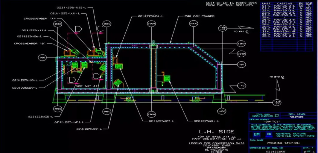
- Layout Sheet: This entails detailed drawings of individual units, encompassing all their components. It offers a comprehensive view of the units' configurations and structures.
2. Non-Unitized Tools:
Non-unitized tools, such as stands and tool changers, can stand alone and can be fully detailed on a layout sheet without the need for a key sheet.
Design Output Guidelines:
- Utilize approved standard components whenever feasible.
- Aim for simplicity and cost-effectiveness in design.
- Ensure compliance with current safety and ergonomic standards.
- Design for controlled and damage-free handling of products.
- Incorporate adequate error-proofing measures such as proximity switches and rough locators.
- Minimize the weight of moving parts while maximizing strength.
- Keep frames and structures simple and robust.
- Design for easy clearance and accessibility for routine maintenance and servicing.
- Consider motion control for any moving equipment.
- Validate clamps and weld guns as part of the designer's responsibility.
10) What do you understand by structuring a design tree? How does it reduce errors during the design process?
Structuring a design tree involves systematically naming all assemblies and parts according to specific standards. Each customer typically has its standard for structuring a design tree.
Properly naming parts and assemblies is crucial because it prevents confusion and facilitates understanding of the design. It allows for easy identification of which project a part or assembly belongs to and helps determine the quantity of items used in an assembly.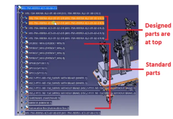
In the provided example, the designed parts are listed at the top, while the standard parts are listed below. The product description or name, such as "H1L-T9A-RRFRA-JG3-00-00-00," follows a specific format:
- "H1L-T9A" represents the project name.
- "RRFRA" denotes the panel name.
- "JG3" refers to the jig number, in this case, Jig 3.
- "00" signifies the unit name.
- "00" serves as the part number.
- "00" is the component number.
This structured naming convention aids in easily identifying and understanding the components within a project.
11) What are Units? Mention 5 types of units.
Units:
A unit is a functional device, often forming part of a complex mechanism, with a specific purpose.
A welding fixture is an assembly comprising various types of units. These units are primarily observed in unitized tools.
Units are classified into two categories:
Simple units: In a simple welding fixture, a combination of different units is present, including:
- Rest unit
- Fixed pin unit
- Retract pin unit
- Rough locator unit
- Sensor unit
- Base unit
Complex units: In a complex welding fixture, alongside some simple units, additional complex units may also be present, such as:
- Slide unit
- Dump unit
Five Types of Units:
1. Base unit:
The base unit is designed to mount all other units, such as clamp units, pin units, rest units, etc. Additionally, other necessary parts for the tool, such as pneumatic valve boxes and trunk cable paths, are also mounted on the base unit.
2. Fixed pin unit:
A fixed pin unit is designed to locate the car panel using pins. Components of the fixed pin unit include pins, pin retainers, shims, blocks, blades, and risers. The pin retainer securely holds the pin in place. Locating pins are used to accurately position a body part for welding, ensuring full constraint to prevent movement.
3. Retractable pin unit:
The retractable pin unit is similar to the fixed pin unit, but the entire pin package is mounted on a retractable pneumatic cylinder. This unit allows the pins to be moved up and down and retracted to a certain distance. It is primarily used for unloading complex panels after welding.
4. Clamping unit:
A clamping unit is designed to clamp or hold the car panel with NC blocks or Mylars using a pneumatic clamp cylinder. This unit clamps the part to be welded after positioning using the pin unit. It utilizes pneumatic cylinders and clamp arms for clamping.
5. Slide unit:
The slide unit is commonly found in complex fixtures and involves a sliding mechanism. It is used in situations where there are space constraints. Components of the slide unit include guide blocks, guide rails, position lock units, stopper blocks, and sensors. Guide blocks and guide rails assist in guiding the slide unit, with the rail often protected by a cover. The position lock unit ensures the slide is locked or clamped in the working position, while the stopper block controls the movement of the slide unit. Sensors detect the end limits externally using proximity sensors.
12) Describe Fixed Pin units & their purpose.
The fixed pin unit serves as a stationary locating device utilized to ensure the proper positioning of a part and prevent any movement. It consists of several components, including the pin, pin retainer, shims or spacers, block, blade or adaptor plate, and riser.
The riser is employed to elevate or increase the height of the unit, while blades are mounted on the riser. Blocks are affixed onto the blade, and shims are utilized as small spacers to accommodate stack-up tolerances. These shims come in various thicknesses, such as 0.1mm, 0.2mm, 0.5mm, etc. The pin retainer securely holds the pin in place, and the pin itself is employed to locate the part and restrict its movement.
The primary purpose of the fixed pin unit is to accurately locate the car panel and prevent any motion. It adheres to the 3-2-1 principle, requiring two pins: one pin restricts four degrees of freedom (four translational), while the other pin restricts two degrees of freedom (two rotational). This configuration ensures precise and stable positioning of the part.
13)What are the different parts of a fixed unit?
Pin:
A pin, also known as a locating pin, is utilized to accurately position a workpiece. These pins are precision-engineered with specific dimensions and tolerances. Typically, two pins are sufficient to locate a workpiece on a single plane. Various types of locating pins are available, and the selection depends on the requirements of the workpiece.
Pin Retainer:
A pin retainer is a component used to securely hold the pin in place. It ensures the pin remains firmly positioned during operation. Pin retainers can be custom-made parts or standardized components readily available in the market.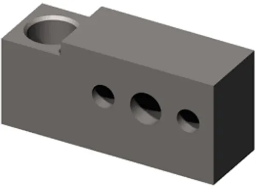
Shims/Spacer:
Shims and spacers are plates of varying thicknesses used to compensate for stack-up tolerances in assemblies. These components come in thicknesses such as 0.1mm, 0.2mm, 0.5mm, etc. They are utilized to correct any generated stack-up tolerances in an assembly, ensuring proper alignment and functionality.
Block:
Blocks can be machined to any required thickness based on the fixture's design and specific requirements. They serve various purposes depending on the fixture's design and intended function.
Blade:
Blades are plates attached to risers, onto which components such as cylinder arms are mounted. They provide a mounting surface for various parts and accessories within the fixture.
Risers:
Risers are standardized components used to elevate the height of the entire unit. They are typically fabricated from plate materials or welded plate and tube assemblies, or they may be created through gas cutting from a single piece of material. Risers play a crucial role in adjusting the height of the fixture components as needed for proper alignment and functionality.
14) What is the purpose of making a Rest unit & describe its parts?
The purpose of creating a rest unit is to provide support to a car panel using materials like Mylar, NC block or rests. Unlike other units, the rest unit solely focuses on supporting the component without applying any upper clamps or forces.
Designing a rest unit is relatively simple compared to other units because it involves fewer parts and serves the single purpose of resting the car panel. This simplicity allows the rest units to be combined with other units, reducing the overall project cost. It can be integrated with a clamp unit for both clamping and resting functions or combined with a locating unit to serve as both a locator and a rest. Additionally, combining locating, clamping, and rest units into one unit further reduces costs.
The rest unit typically does not include any cylinders. Its main components include:
1. NC blocks/Mylars:
- Mylars are jaw-like components that hold the panel from the top and bottom.
- They prevent deformation of the part during welding and are specifically designed for resting purposes.
- Mylars are categorized into clamping mylars and resting mylars, with only resting mylars used in the rest unit.
2. Risers:
- Risers are manufacturing parts used to elevate or raise the assemblies of fixtures.
- One end of the riser is attached to the base unit, while the other end is attached to the blade.
- There are two types of risers: L-type risers, which are welded with a stiffener added for support, and square tube risers, which have a frame-like structure.
3. Blade:
- Blades are plates attached to the risers and are also used for mounting cylinders, arms, etc.
4. Shims:
- Shims are thin, often tapered or wedged pieces of material used to fill small gaps or spaces between objects.
- They may be used to support, adjust for better fit, or provide a level surface.
- Shims can also function as spacers to fill gaps between parts subject to wear.
15)What are the basic fundamentals of designing a Sensor unit?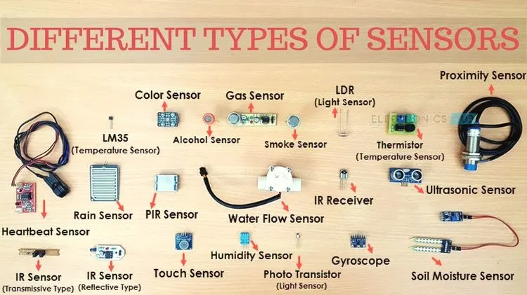
A sensor is a device that detects or measures a physical property and records, indicates, or responds to it. In the context of welding fixtures, a unit built to sense components or car panels using electrical sensors is referred to as a Unit Sensor. The output signal of the sensor is then sent to a PLC (Programmable Logic Controller) for further processing. Various types of sensors exist, including proximity sensors and laser sensors.
Fundamental considerations for designing a sensor unit include:
1. Sensing Every Panel:
- Every loose panel being welded by the tool should be sensed by the sensor unit.
2. Number of Sensors:
- Each panel should be sensed by 1 or 2 sensors, depending on the size of the panel and the requirements of the application.
3. Adjustable Mounting:
- Each sensor should be mounted in a way that allows adjustment in three directions, typically to ensure optimal positioning and alignment with the panel being sensed.
16)What is a Rough locator unit & what are the basic fundamentals to consider while designing it?
A rough locator is a device used to guide a workpiece into its proper position. It's particularly useful when manual operators are involved but also finds application in automated processes. Acting as a foolproofing method, rough locators ensure accurate positioning of the workpiece.
Considerations for designing a rough locator include:
- Placement: Rough locators should be positioned at the edges of the car panel they are intended to guide.
- Alignment: They should align with the angle of the car panel's edge, maintaining a distance of 2-5mm from the edge.
- Guidance: Rough locators guide the panel into locating pins for precise positioning.
- Engagement: They should begin guiding the car panel 10-15mm before full engagement.
- Entry Angle: Rough locators are designed with an entry angle for the car panel, typically 30-45 degrees.
- Adjustability: Rough locators should feature two slots for easy adjustments, aligned with the direction of car part guidance.
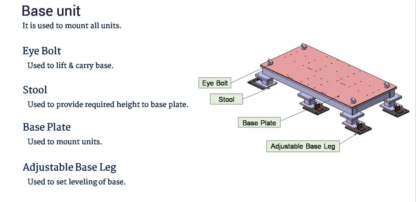
17)What is a Base unit and describe its parts?
A base unit serves as the foundation for mounting all other units such as clamp units, rest units, and pin units. It also provides a mounting platform for additional tools like pneumatic valve boxes and trunking cable paths. The base unit can either be securely fixed to the ground or designed to be movable.
Components of the base unit include:
1. Floor plate:
- The floor plate is utilized to mount the entire base unit onto the floor. It contributes to achieving the flatness of the fixture.
2. Weld bars and pedestal:
- The pedestal is a structural element where the entire base unit is mounted.
3. Eye bolt:
- An eye bolt features a loop at one end and is used to firmly attach a securing eye to the structure. When the fixture table needs to be moved, cables are attached to this bolt to facilitate transportation.
4. Measuring hole cover:
-The base plate incorporates several holes for mounting units. These holes are measured by a CMM (Coordinate Measuring Machine) to ensure accurate positioning. A cover plate is used to protect these holes from dust or damage.
5. Valve box and trunking channel:
- The valve box supplies air to all pneumatic cylinders in the assembly. It contains solenoid valves used to regulate the airflow from the cylinders to the valve box.
6. Base plate:
- The base plate is a heavy plate with significant thickness as it supports the weight of the entire assembly. It is machined to maintain parallelity and features drilled holes for mounting the various units onto it
18)What is a Dump Unit and what are its functions?
The dump unit is a complex unit employed in situations where there are space constraints or other geometrical limitations that prevent the normal mounting of clamp units, rest units, etc. It incorporates a dump cylinder to facilitate the clamping and unclamping of the car panel.
Functions of the dump unit include:
1. Addressing Constraints:
- The dump unit is utilized when specific constraints prevent the standard assembly of components.
2. Dump Cylinder Action:
- It features a dump cylinder responsible for the opening and closing actions required for the operation.
3. Clamp Cylinder:
- Additionally, the dump unit may include a clamp cylinder unit to further secure the car panel in place.
The dump unit is characterized by its complexity in design and is employed only when necessary due to its specialized function.
19)What is a Slide unit? Mention where Slide units are commonly used.
Slide units serve as positioning units utilized to position car parts or panels, units, and robots for further operations, especially in areas with space constraints where other units cannot be feasibly employed.
Components of slide units include:
1. Sliding cylinder:
- The sliding cylinder is responsible for moving the panel from an open position to a closed position and vice versa.
2. Position locking unit:
- This unit is utilized to lock the plate at a particular position, preventing it from moving.
3. Guide rail:
- The guide rail facilitates the smooth movement of the plate from one position to the next, ensuring precise positioning.
4. Stopper block:
- The stopper block is employed to control the motion of the sliding unit, restricting its movement within defined limits.
5. Sensor unit:
- A sensor unit is incorporated to detect whether the component is moving properly or not, ensuring accurate positioning and operation of the slide unit.
They are used in BIW fixtures and assembly lines to position car parts or panels, units, and robots accurately for welding, joining, or other operations