Week 3:- BiW Fixture Design Methodologies Challenges
1. Biw design methology
It is nothing but the steps followed while designing fixture it includes concept study and different design methods.
BY taking the component also studying the different concepts to design the fixture based on the component the fixture is designed and also study of inputs from customer.
The various stages of design methodologies
1.Purchase order
2.Input from customer
3.percentage completion criteria
4.Design output
1.Purchase order
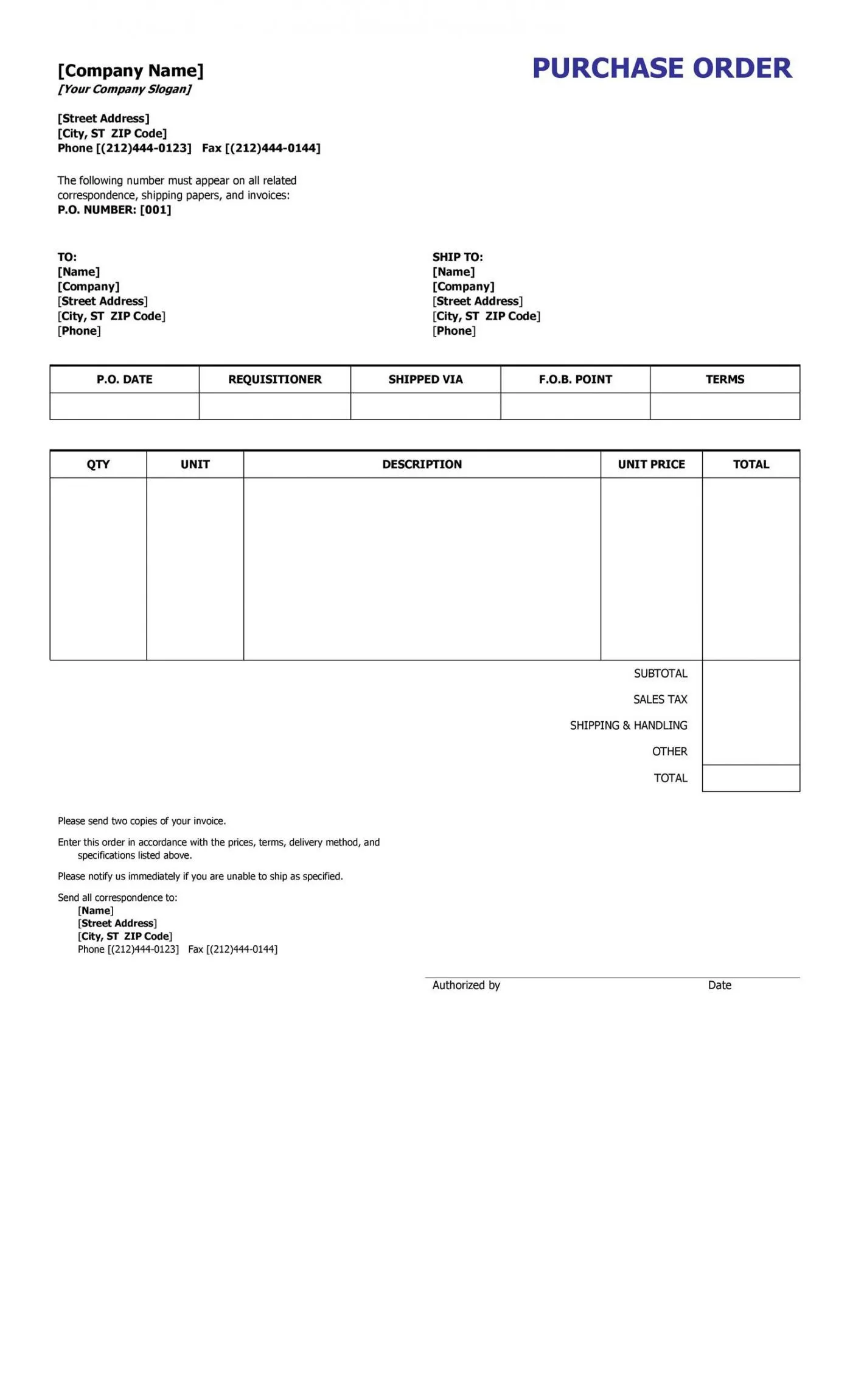
Purchase order is nothing but getting the conformation from the customer to start the design. In the purchase order it includes quantities to be order and quote from side and conformation from customer based on the given quote. After receiving the purchase order the schedule for work is under process.
2.Input from customer
Getting input from the customer what type of design standard should be followed and also other data is given by the customer.
some of data we get from customer include
1.Functionlal requirement
It is nothing but what types of function of the fixture like welding, guling, riveting and other functions mat include etc.
2.Preferred standard component
We are gone a receive some standard component data from the customer based on that we have design the fixture .By use of standard parts the time will be saved and designing can be done faster.
3.Car products
The input we get from the car products are GD& T, PLP, cad files, clamp plan.
4.Layouts
Layout shows the plan for assembly where provides information of flow of parts, station pitch, robot stations, accessories like tool changers & tip dressers, sub assembly links, plat form height, loading/unloading sequence/height.
5.Ergo data
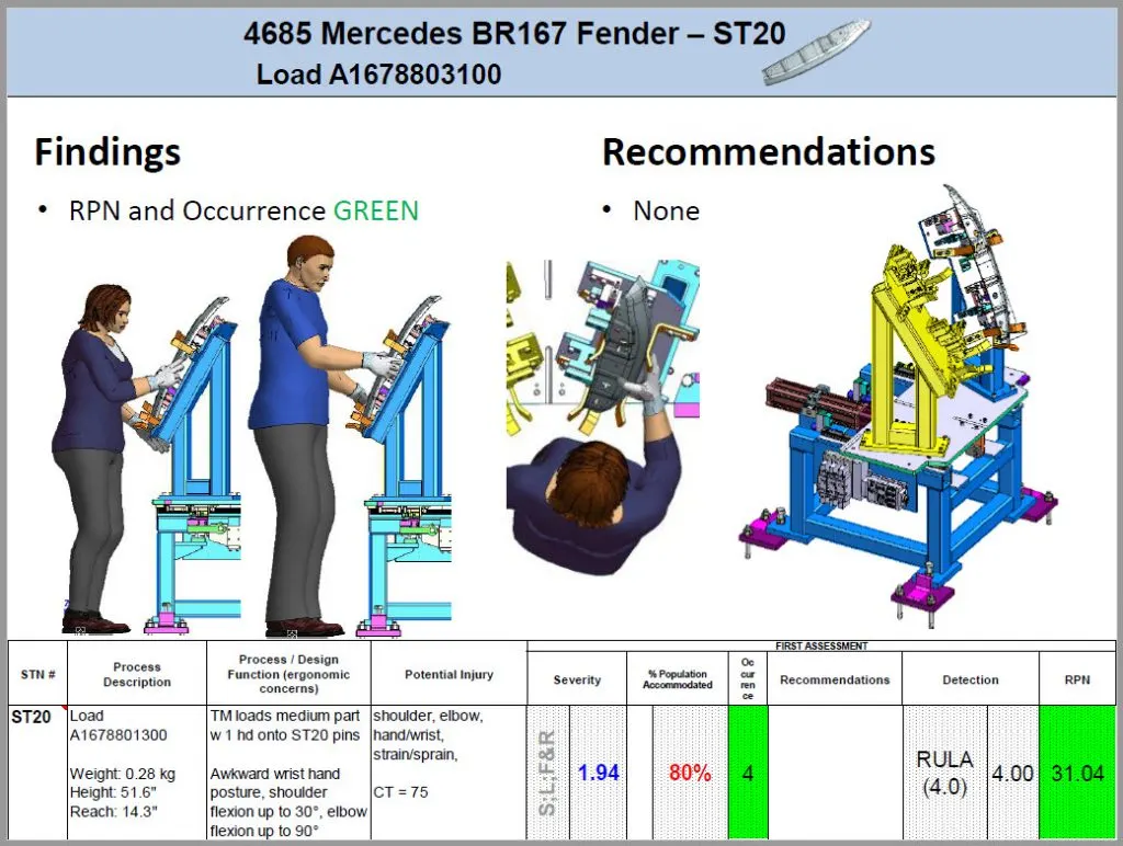
It is basically data from customer for operator what type of standard should be followed while designing. It helps the operate to under stand how to operate fixture.
6.Weld study
It gives details about the study of particulars gun that we use for welding. Also type of welding is done and also how many welding points .
7.Standard detailing template
The details given from the customer for 2d drawing as per the standard
3 Percentage of completion criteria
It shows the work schedule followed by the company fromthe start to finish of the design.
Percentage completion
1.0% to 25% - Inputs and concept design
2.25% to 40% - Concept approval and simulation check
3.40 to 85%-design and detailing
4.85 to 100% - Check and finish of design
4.Design output
In this submitting of 3d files,2d detailing, bill of materials and some standard used from while designing the fixture and some other documents while designing the fixture.
2.Inputs required from the customer to start designing a Fixture
1.Funtional requirement.
2.Preferred standard components
3.Car products
4.Layouts
5.Ergo data
6.Weld study
7.Standard detailing template
1.Functinal requirement
It is basically what are the needs of customer in fixture design and also requirements from the customer what type of fixture for example fixture like welding, gluing, riveting and other functions may include, hemming fixture, checking fixture.
2.Prefeerd standard component
IN this the customer as already got some of the standard component based on that the design should be carried and by use of standard component the time saving can be done and also design speed can be more. Manufacturing of every part takes time if standard components are not used. Customer gives what types of standard should be used based on that design is done. By using standard components it saves money and time.
Some of the companies Offer standard components
1.Standard like ABB, NAAMS, DESTACO, ZYTRAN, TUNKERS,misumi, are used in design & manufacturing of fixtures.
2.Standard parts like Risers, L-blocks, retainers, pins, NC blocks, Shims.
3.Customer may also have cylinders, sensors because they are costly.
4.Only less robots are used because the robots cost is more tool changers are used ahange the tool.
3.Car products
1.GD&T
Provides information of clmps,pins,dumps,and slide information. It also gives information of slides opening aand closing
2.Parts list: It gives the information of parts and there thickness, quantity, and also material used and parts are named based on assembly numbers.
3.Clamp plan: It provides information of location of pins,rests,dumps,clamps.
4.3D files: The 3d part model given from the customer for designing of fixture
5.Assembley sheet: It shows how the parts are assembled step by step and also how parts are moved from one station to other station. It gives detailed information of joining how it is joined.
4.Layouts
It gives information of how the parts are moved from one station to other station and also give information off flow of parts ,robots, loading and unlaoding sequence of the parts,tool,guling gun etc.
5.Ergo data
It is a study of human movement and behoviour.
As same as preferred standards, different companies follow different standards of ergo data. We have to follow the customer standards of ergo data.
The inputs of ergo data will given by the customer mostly in case of manually operated fixtures/manual fixtures.
Ergo data data mainly used for operator comfortability and also to increase the production efficiency.
It also gives operator to be comfortable withe the use of fixture.
6.Weld study
It is includes data of weld gun and also weld matrix will be given it shows where the welding is done and there two weld points one geo weld point and other is respot weld points.
3.What is the input we get from "Car Products"
1.GD & T
Geometric Dimension and Tolerances. It provides information of locating pins, rest, clamp, damp & slide unit information of each station. Also includes the information of sequence of openings of clamps, dumps & slide stroke information. Geometric Dimensioning and Tolerancing is a set of rules and symbols used on a drawing to communicate the intent of the design. The core purpose of GD&T is to make sure that the part functions properly. With focus being on the function of the part, GD&T allows for larger tolerances for less important design features, which results in a cost savings for manufacturing.
Why GD and T is Important
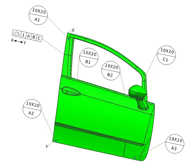
It helps while assemble of parts it helps assembly faster also production can be made easer by reducing and cost while manufacturing.
BY using gd and t manufacturer and designer can communicate with the drawing and manufacturer understands the drawing based on gd and t.
2.Part Lists
It is the list of parts which assembled .Parts lists helps what material is used and cost and qty, and also what all parts are used while designing like for example clamps, locating pins, t-bolts etc.
3.Clamp plan
Clamp plan provides the information of location of pins, rest units, clamp unit, dump, etc. It is the important input from customer. The clamp plan/position should not be changed without the knowledge of customers.
4.3d files
The 3d file is the 3d model which is received from the customer to design fixture based on the 3d model. The file may be in the type step file.
5.Assembley sheet
It shows how the parts are assembled step by step and also how parts are moved from one station to other station. It gives detailed information of joining how it is joined.
Where the robots are placed it gives details of loading and unloading.
It shows the operations to be carried out in stages and also what operations to be carried out.
By assembly sheet we can get to know how the process is going on from one station to other station.
It also shows where the tools are placed in the assemble.
4.Clamp plan
A clamp is a fastening device used to hold or secure objects tightly together to prevent movement or separation through the application of inward pressure. The work piece must be held rigid while undergoing operations.
Importance of clamp plan
- It helps in locating the part with moving the part
- Clamping need to be strong and rigid enough to hold the blank firmly
- It keeps the part where rigid without moving
- we can change our design a little bit here or there, but we should not change the input design data about the clamp position or the pin position.
- In the Clamp plan there is clamp unit, pin unit and it is more detailed. It also gives extact coordinate x,y,z where the exact design to be carried out.
5.Purpose of layout
The layout helps to understand robots and fixture. which all the fixtures assigned to robots. It shows entire assemble pan to understand the process that are going on.
Layout provides the information of flow of parts, station pitch, robot stations, accessories like tool changers & tip dressers, sub assembly links, plat form height, loading/unloading sequence/height.
Layout sheet will give you information about all the fixtures are placed, the robots are going to work on it.
Process that are taking place in layout
1.Flow of parts
It shows the flow of parts in in the shop floor where the parts move from one station to other station.
2.station pitch
It is the distance between the two station on the shop floor.
3.Robot stations
It is basically where the robots are placed on the shop floor it is shown in layout with fixtures around the robot.
4.Sub assembly link
It is link between sub assembly fixture with the main assemble
The main use of layout One of the main purpose is to get the information about the space constraint which helps to develop the robotic cell without any clash during working.
6) Ergo data
Ergo data is the data given by the company what all the parameters to be followed while designing fixture and height of fixture, length of the fixture.
It shows at what distance the operator should be from the fixture while is operated manually by the operator.
Ergo data is basically only for human safety different companies have there own ergo data to keep the operator safety and also there health.
The ergo data is mainly used to make the operator comfortable which may leads to improve the efficiency in cycle time & production.
Ergo data is nothing but the data or inputs which gives the human factors engineering data, between the operator & his working environment.
7)Weld study
It is the information given by the customer what type of weld gun there gone used to weld the parts.t gives the study of particular gun that we use for weld, No. of spots to be welded, sequence of weld, position of weld in the components.
It is a study of weld gun and no of spots to be welded and position of the component.
The weld spots classified into two main types
1.Geo spots points
Geo spots are the red spots whee one component is joined with the other part. Which is same station to be joined.
2.RE spot points
Re spots are one component is joined with the other component. Component of different stations are assembled.
8)What are the criteria for percentage completion in the designing stage
It is basically shows the how the design process is going at what stage the design.
There four stages of completion criteria
1.Input & concept design
2.Concept approval and simulation check
3.Design freezing an detailing
4.Check and dispatch the design
1. Input and concept design
It is basically getting the part model from the customer based on the part the concept is designed it is bascially 0-25% work is done if input and concept design is done.
2.Concept approval and simulation check
Concept approval from the customer and then carried with simulation check then if the both concept approval and simulation check is done then it shows 25 to 40% of work is done then design freezing and detailing is done at the next step.
3.Design freezing and detailing
It is basically checking the design and detailing is nothing but gd & t and other 2d drawing are done then the 40-85% of work is done then in the final stage the checking and dispatch is done to the customer.
4.Check and Dispatch
Check the design and dispatch the design to the customer with the documents after design completion it 85-100%
9)Output in design
It is basically giving the output the customer in 2d drawing and 3d model. It includes bill of material and other extra documents and also what all standard components where used while designing the fixture.
The output of 2d and 3d model is given by tools called
1.unitized tools
2.Non unitized tool
1.Unitized tool
Multi units on the common base
1.key sheets
It includes fixture, tools, multi units are placed and it the drawing is viewed with 3d model in orthogonal view .
2.Layout sheet
It is shows ever single part drawing which is present in key sheet with detailed view of every part with dimensions .Also location of the parts which is present in the key sheet.
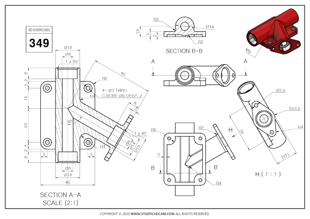
The Design Output Should Compile Following Points:
- Approved standard components are to be used wherever possible.
- Design must be as simple & economics as possible.
- Design must be comply with all current safety & ergonomic requirements.
- Design must provide for controlled & damage free handling of product.
- Adequate error proofing provision must be incorporated into each design by proving proximity switches, rough locators, etc.
- The weight of the moving parts must be kept to a minimum while maintaining maximum strength.
- Frames & structures are to be simple & study.
- Design clearance & accessibility for routine maintenance & service.
- Motion control must be considered on any moving equipment’s.
- Designer is responsible to validate clamps & weld guns.
10)Structuring a design tree
It basically helps to recognize in assembly recognition and also what are the parts designed and what are the parts which are standard which is used while designing the fixture.
It also helps to know how many quantity being used it gets easier while inspection, asembley and also helps manufactured to manufacture.
If the tree structure is not proper we may get cofusion and also parts may be manufactured more or less then time waste and money waste.
while designing the fixture first there should be manufactured part should be mentioned first and standard parts at the last to recognize what all the parts are designed by the designer.
Tree structure makes help designer , customer and manufacture to read the assembly easily.
Tree for the components should be renamed in the manner
- P001_Z03_ST09_00_00_R
- P001 – represent the project name.
- Z03 – Zone name.
- Panel name will also be mentioned in some case.
- ST 09 – Station name / J03 – Jig name will be mention sometimes.
- 00 – unit name.
- 00 – Part number.
- R/L – is representing the right hand side / left hand side of the panel.
- The other renamed title explained in video is
- H1L_19A – Project name.
- RRFRA – Panel name.
- JG3 – Jig name/number.
- 00 – unit name
- 00 – Part number.
- R – Indicates right side
Error which overcome by using tree structure
- It helps the designer to know what are standard parts and designed parts
- It makes easy to get to know the quantity of each part
- It is easy while assembly the entire design
- It helps the customer to know what all the components are in the assemble.
- If the designer are missed any of the component it makes easier to get know by tree structure.
- By the help of tree structure we can separate each part.
11) Units
A unit is a device that has a specified function, especially one forming part of a complex mechanism. There are different types of units in biw .
There two types of units
1.Simple units
- Rest unit
- Fixed pin unit
- Retract Pin unit
- Rough locator unit
- Sensor unit
- Base unit
2.Complex unit
- Slide unit
- Dump unit
a)Rest unit
It is basically designed to rest the car panel using nc(numerically controlled) block,mylars.
b)Fixed pin unit
It is basically designed to locate the panel in the right position using pins that will be fixed.
c)Retract pin unit
It is basically if two panel need to be welded we cannot use fixed pin instead we go with retract pin unit which helps pin move with help of pneumatic mechanism.
d)Rough Locator pin
Rough locator are designed to guide the operator to locate car panel on to the pins. The rough we can get standard part.
e)Sensor unit
It is a basically used to sense the car panel. Sensor units helps to know the panel is welded in ever position.
f)Base unit
It is unit which all the units mounted on it.
12)Fixed pin unit and there purpose
Fixed pin unit is basically where the pin is fixed the doesn't move it makes part fixed without moving it is also designed to locate the car in order to fix the pin rigidly without moving the fixed pin unit is used. Fixed pin unit basically have pin, pin retainer, shims/spacers, block, blade or adaptor plate. Pin retainer support that pin. If one panel is there to be fixed than fixed pin unit is used.
Purpose of fixed pin unit
- In order to restrict the transverse and rotational motion of the panel the fixed pin unit is used. Pin makes sure that the pin is not moving a inch for example if the panel is moved than the entire assembly will be wrong.
- To restrict 12 degree of freedom there should be 2 pins be used .
12)different parts of fixed unit
1)Pin
Pins are used for accurate and constiently position of the panel. It also used for locking the rotational motion of the panel.
- The body part is constrained by a set of appropriately locating pin so total constraint by locating pin should be fully constrained at all times to prevent any movement.
There two types of pins Generally used
1.Round pin
2.Diamond pin
1.Round pin
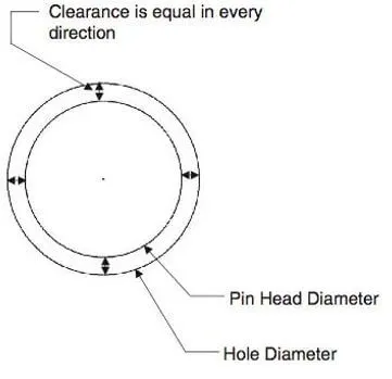
It is used for 2ways locating panel only.When a round pin and diamond pin are used together, the round pin is the primary, 2-axis locator, while the diamond pin is the secondary, 1-axis locator.
2.Diamond pin
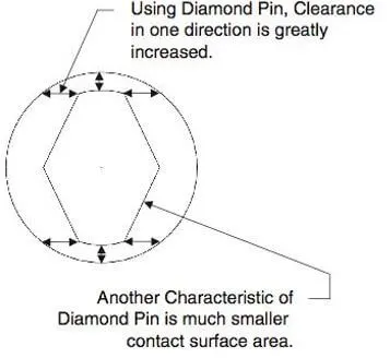
The Diamond pin oriented properly allows minimal misalignment in the X axis, but prevents the work piece to move in the Y direction.
2)Pin Retainer
The body part is constrained by a set of appropriately locating pin so total constraint by locating pin should be fully constrained at all times to prevent any movement. It is used to hold pin firmly without any movement and also to retract the pin from the panel.
3)Shims/spacers
Steel shims or steel packers are spacers used to fill gaps between objects. Shims can be made of various materials besides steel, including plastic shims. Shims also come in a variety of shapes and sizes. This includes square shims, horseshoe shims, rectangular shims and many more.
In order to maintain proper tolerance shims are used if there a minimium gap of 0.1 to 0.2mm than shims are used to cover the space.
Shims comes in a size of 0.5mm,1mm,5mm shims.
Shis helps to avoid stackup tolerance while assembling the entire component.
4)Riser
The part which is mounted on the base plate and holds a clamp or pin cylinder on it, is called Riser.
Riser can be Standard Part or manufactured part, it varies from project to project.
A riser can be a Single part or welded part.
Standard risers also have various shapes and sizes.
5)Blade
The plate which connects Riser to the Clamp cylinder is named Blade. This plate plays an important role in building the unit. The plate can be of any shape. But we need to keep in mind that the plate should be as compact as possible.
6) L Block
A plate shaped as L is called an L block. This part is used as a connection between mylar and Blade. Generally, L blocks are used to provide shimming. It is not necessary that L blocks are only used for shimming, its uses changes as per the requirements, At some places, it is used just to connect one part to another. Similar to the L block one more block is used which is in the shape of T. So this block is called a T Block.
13)Purpose of rest unit and there parts
It is one of the simple unit it basically designed to rest/support the car panel using NC blocks/Mylar, rest. In this most of parts are standard parts.
Parts of rest unit
1.Nc block/MyLARS
Mylars are the part which are holding the panel from top & bottom.It wont allow the deformation of the part due to welding stresses.Mylars are mounted on any block or plate with Shimming, So that height of mylar can be adjusted accordingly at the assembly level. Shima are also used Shimming can be 1 directional, 2 directional, or 3 directional as per the NC cut.
There are two types nc blocks/mylars
1.Clamping mylars
2.Resting mylars
2.Risers
The part which is mounted on the base plate and holds a clamp or pin cylinder on it, is called Riser.Riser can be Standard Part or manufactured part, it varies from project to project. A riser can be a Single part or welded part. Standard risers also have various shapes and sizes. The riser design may vary based on type of unit use.
3.Blades
It is theype of plate which connects the riser and the cylinder. This plate plays an important role in building the unit.
The plate can be manufactured based on any shape.But we need to keep in mind that the plate should be as compact as possible.
14)What are the basic fundamentals to design a Sensor unit
Sensor unit
A sensor unit is a unit designed to sense the car panel by using electrical sensors.
This signals from the sensors will be fed to the PLC and so the next process will be executed by the signal.
- Every single loose panel which are being welded in a tool should be sensed properly.
- The panel should sensed 1 or twice based on the panel size.
- Every sensor should be mounted in 3 directional adjustable way in general
- We should try to minimize the size of sensor as much as possible.
Types of sensor
- Proximity sensor
- Laser sensor
- Photo electric sensor
1.Proximity sensor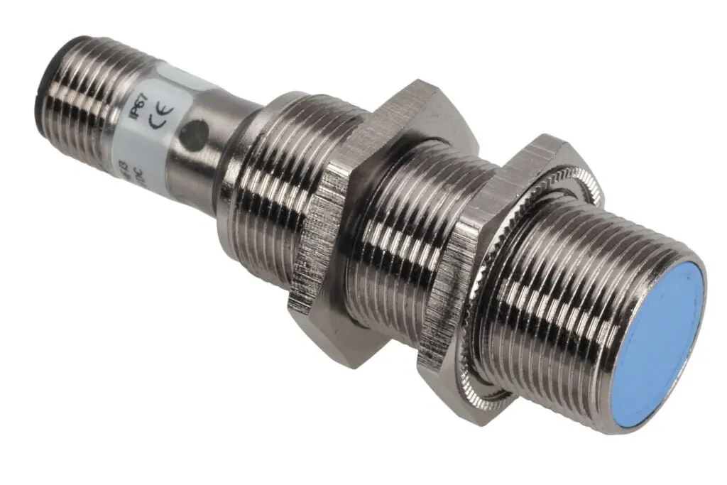
The proximity sensor is one of the oldest electronic components used in automation to detect objects. A proximity sensor is a general word for sensors that are designed to detect without contacting the detecting object and replace contact detection methods such as limit switches.
Types of proximity sensor
1.Inductive proximity sensor
2.Capacitive proximity sensors
3.Magnetic proximity sensor
2.Laser sensor
Laser sensor is basically sensor which used to sense the multiple object.This sensor uses a laser to produce light within a straight line.Its visible ray mark of the laser makes arrangement very simple. For thelong panels the laser sensor are preferred.
3)Photo electric sensor
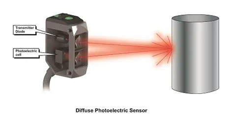
A photoelectric sensor is one type of device used to detect a difference in the level of light obtained from the source of light.. These sensors detect different objects, the presence/absence of an object, changes within surface conditions, and measure the distance between an object & a point & other devices with different optical properties.
This sensor uses light to detect an object without physical contact.
The sensing range of this sensor is long as compared to proximity sensors like 800 ft. or 243.8 m.
This sensor notices invisible markings on products. The size of this sensor is smaller.
17)What is a Rough locator unit & what are the basic fundamentals to consider while designing it
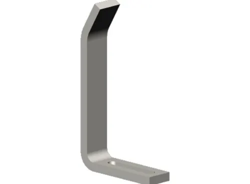
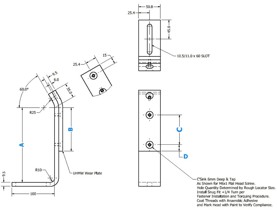
It is the part designed to guide the operator to locate the car panel onto the pins. The rough locator can be manufactured or they can standard part.
Basic fundamentals to consider while designing Rough locator
1.Rough locator should be placed at the edges of the car panel, which has to guide.
2 .Rough locator should be placed in the same angle of the car part edge with a minimum distance of 2 – 5 mm from the edge of car part.
3.Rough locators should guide the panels in a pin assemble direction in general.
4.Rough locators should start guiding the panel before 10 t0 15mm to the start of the pin engagement.
5.Rough locators should be designed with entry angle for car part entry as shown in the above figure.
6.Rough locators should be designed with two slots to mount for easy adjustment in general.
7.The slots should be in the direction of car part guiding.
18)What is a Base unit and describe it's parts
Base unit is designed to mount all other units like clamp, pin unit, rest unit etc. also other parts like pneumatic valve box, trunk cable path will also be mounted on to a base unit.
Parts of base unit
- Valve box.
- Trunking channel.
- measuring hole cover.
- Eye bolt.
- Pedestal.
- Floor plates.
1.Valve box
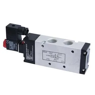
Valve box is basically a box which supplies air to all the pneumatic cylinders assembled in the fixture. It is a device which includes solenoid valves .It has one inlet and one oulet.
2.Trunking channel
Trunking channel is a kind of cable duct, which helps to guide and protect the wirings/tubes used in the fixtures.
3.Measuring hole cover
To measure the clear opening size for your cover you need to take the measurements from the inside walls of the manhole from one side to the other. The measuring hole helps in CMM inspection & QC inspection.
4.Eye bolt
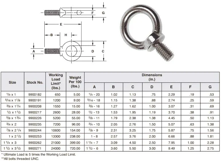
It used to frag the assembly to the required position the eye bolt are used. Eye bolt different standards available. Eyebolt is used to frag or lift the base unit while relocating.
18)Dump unit
Dump unit is where you assemble component if you have certain constraint. Here you will have clamp unit, pin unit attached & panel will be assembled.
Dump unit use in different way. It has dump cylinder & complex design. It consists of dump cylinder to perform the operation of clamping & unclamping car panel.
A dump unit can have more than one cylinder to perform such operation.
The first cylinder dumps the assembly carrying clamp mylars, pins and then this assembly performs the required operation.
20)Slide unit
Slide unit is used if there is no possibillty of using other units if the design is complex then slide unit is used. The construction slide unit is less compare toother units.Slide units are positioning units, which are used to position the car part or panel, units, weld gun, robots for further operations.
The slide units are used if the weld spots are less.
By using slide unit we can minimize the cost of the robots .
Slide units can be calssified into three types on the base of the prime mover used
1)Manual slides
2)Hydraulic/pneumatic slides
3)CNC slides
It may also be classified depending on application as
1) Horizontal slide
2)Vertical slide
3)Angular slide