Week 3:- BiW Fixture Design Methodologies Challenges
What is Design Methodology?
Design methodology is the process of creating a system or strategy for a specific situation. This process is used throughout the idea design stage. It is the research of design procedures, processes, and concepts. The secret to design methodology is to identify the best solution for each design problem, whether it be in industrial design, architecture, or technology. The design process emphasises the use of brainstorming to promote original ideas and collaborative thinking to go through each recommended notion and find the best solution. Meeting the needs and preferences of the end user is of utmost importance. In design methodology, basic research techniques like analysis and testing are also applied.
The procedures employed during the concept designing stages of fixture design are known as design methodology.
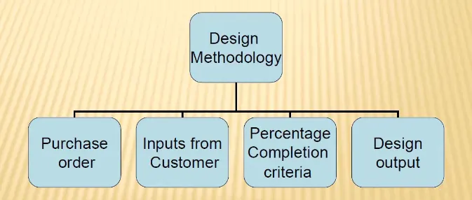
The following tree shows the four stages involved in the design methodology.
1. Firstly, order is purchased.
2. Inputs from customer is taken for creating design specifications for the respective product/service.
3. Percentage completion criteria is followed in design and dispatch stages of fixture design.
4. The design output is cretaed in form of 3D models and 2D drawing of tools.
What are the inputs required from the customer to start designing a Fixture?
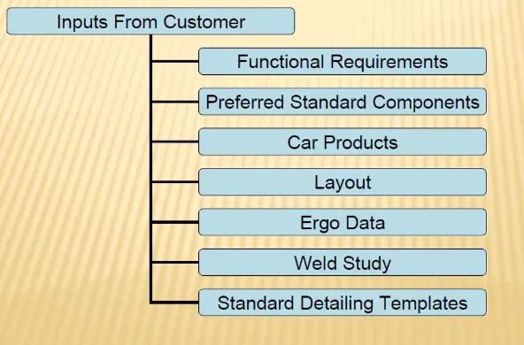
Following are the inputs required from the customer
1. Functional requirements of the product or servcice that the customer has given order for. It will decide basic design constraints for the product.
2. Components that the customer would prefer in the product. It will eliminate the unnecessary components in the product for it's full-functioning.
3. Car products such as 2D or 3D files to study geometrical dimensions and tolerances, clamp plan, process sheet
4. Layout for the manufacturing of the product in a factory.
5. Ergo data provides data for manual operation.
6. Weld Study is the study of particular gun which gives position, number of weldings in the product.
7. Standar Detailing Templates gives information about the details of particular components.
What is the input we get from "Car Products"?
Car Product contains following inputs
GD&T: locating pin, rest, clamp, dumps, slide information, sequence of opening of clamp, slide stroke information
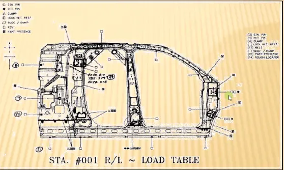
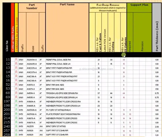
Part List: It gives information about the types of assemblies are going to be. Such as in hood, inner panel, outer panel, hinge assembly etc.
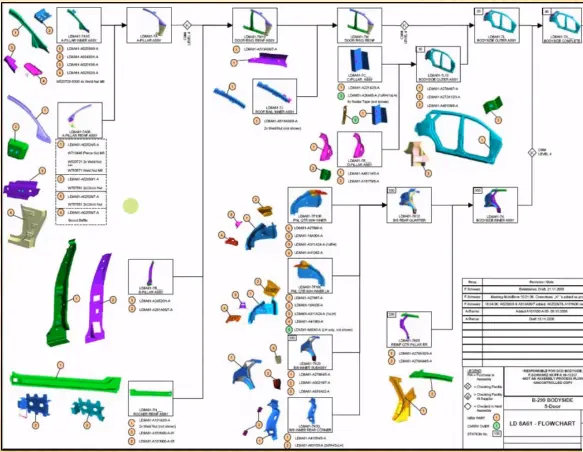
CAD file of Car Part: It gives information about the 3D modeling of the parts
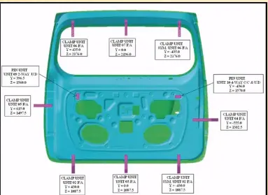
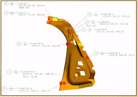
Clamp plan: It decides how the parts will be held and where exactly the clamps, rest, pins and dumps will be in the fixture. It should not be changed.
Product Assembly process sheet: How to follow the steps to assemble the parts to get the desired outcome.
What is the Clamp plan?
A clamp is a fastening device that firmly fastens items together, inhibiting the movement of parts or sub-assemblies in relation to one another. Clamps are found in almost every workshop because they serve the essential function of substituting a reliable extra pair of hands that every handyman needs to complete certain specific tasks.
Clamp plan provides the location of pins, Rest, Clamp, Dumps etc. The location of the clamps should not be changed without asking.
What is the purpose of a Layout?
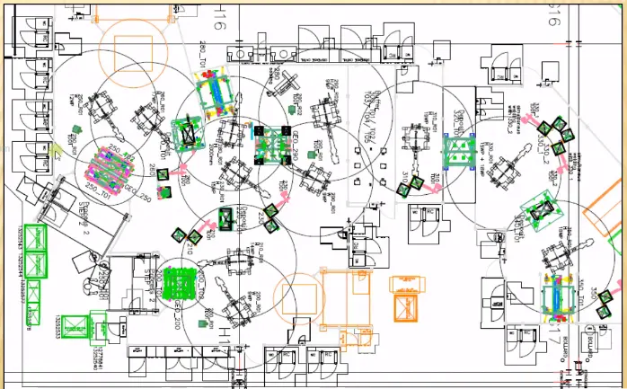
The layout gives complete details on the item/workpiece, tool/robot that will be utilised, and its capabilities.
Layout Provides information of
a. Flow of parts
b. Station Pitch
c. Robot Stations
d. Accessories like Tool changer and tip dresser
e. Sub assembly links
f. Platform height
g. Loading/Unloading Sequence/heights
In the following image, the circles basically provide information about the robot's coverage area.
What is Ergo data?
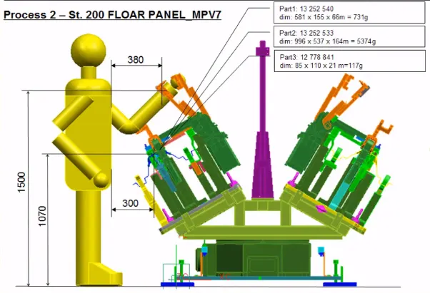
The human behaviour and movement are mentioned under ergo data. It gives details on the safe operating zone for humans and their capacity to reach heights.
What do you understand by Weld study?
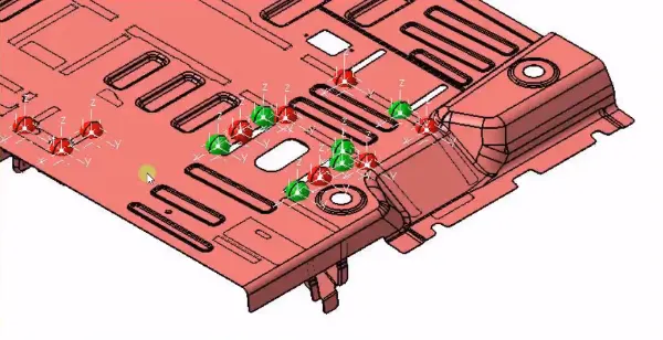
Weld Study includes
1.Weld gun Details
2.Weld Matrix & Weld Points
A) Geo Weld Points
B) Re-spot Weld Points
3. Weld gun details
What are the criteria for percentage completion in the designing stage? Explain it in detail.
The designing and dispatch phases of the welding equipment adhere to a percentage completion objective.
0 to 25%: Input and Concept Design
25–40%: Concept approval and Simulation Check
40-85%: Detailing and Design Freezing
80 to 100% : Final Check and Dispatch
Brief about "Output" in design.
The output is 3D models and the 20 drawings of the tools.
Two different types of drawings are necessary for unitized tools (multiple units on a common base).
Key sheet: A list of the units and where they are located on the tool base.
Layout sheet: A detailed depiction of each unit that shows all of its parts.
Non-unitized tools: Tools that can stand alone and can be detailed completely on a layout sheet.
The following details should be included in the design output.
a. Whenever possible, approved standard components should be employed in the design.
b. Design must be as straightforward and cost-effective as possible.
c. Design must adhere to all current ergonomic (less effort) and safety standards.
d. Product handling must be free and the design must be completely under control.
e. The moving must be done with the least amount of weight possible while still having enough strength.
f. For routine maintenance and service, accessibility clearance must be obtained.
g. Motion control must be taken into account for moving machinery.
h. Clamps and all weld guns must be validated by the designer.
What do you understand by structuring a design tree? How does it reduce errors during the design process?
When a design tree is organised, all of the assemblies and pieces are given names that adhere to a particular standard. Varying clients have different expectations for how a design tree should be organised. It is a crucial technique that enables us to determine which project, tool, or unit a certain part or assembly belongs to. This aids in preventing errors from occurring during design research, production, assembly inspection, etc.
If the parts or assemblies are not labelled appropriately or the design tree is not structured correctly, it will be difficult to grasp the design and there may be significant chances that an error will be made. When a fixture, unit, or component is named, it indicates to which project, zone, or assembly it belongs. It can assist us in determining the number of identical or different sorts of goods that are being used in an assembly.
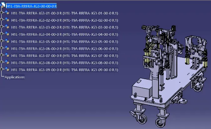
What are Units? Mention 5 types of units.
In general, a unit is a machine with a specific purpose, particularly one that is a component of a complicated system. A welding fixture is an amalgamation of various types of components. As the name implies, only the unitized tool will display the various units.
- Fixed pin unit
- Retractable pin unit
- Rest unit
- Clamp unit
- Sensor unit
Describe Fixed Pin units & their purpose?
The fixed pin unit is made to use pins to locate the automobile panel. It is made up of a variety of components, including a pin, pin retainer, shims or spacers, a block, a blade or adaptor plate, and a riser.
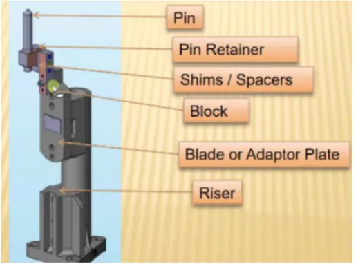
What are the different parts of a fixed pin unit?
The components of a fixed pin unit include a locating pin, a pin retainer, shims, a block, a blade or adapter plate, and a riser. Because the locating pin is a crucial component, it must be extremely accurate, hence the pin unit should have a tighter tolerance.
PIN: Pins are used to limit the degree of component freedom. Locating pins are typically utilised for precise, controlled positioning of a work item. To accurately identify the work item on one plane, two locating pins are typically sufficient. Locating pins come in a variety of designs that can be used in a design. For simple panel loading, a combination of round head locating pins and diamond head locating pins is typically employed.
RISER: Riser is a typical component that gives the Pin unit and clamp unit the height they need. Riser needs to be strong enough to support the weight of the car panel, the clamping cylinder, and the blades.
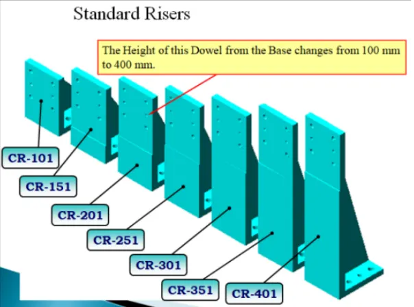
BLADE: The component attach or join Blade refers to the block and riser. spending some time clamping blade-mounted cylinders.
SHIMS: Shims are employed to prevent the dimensions or coordinate variance brought on the stack up tolerance. Shims are employed in both directions of translation. Shims are common components that must be added to meet client criteria.
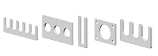
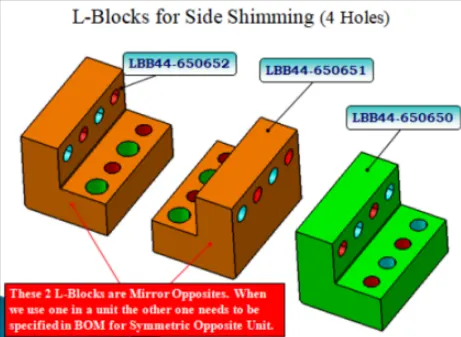
BLOCK: The pin retainer is attached to the blade via a block. Blocks are typically L-shaped, however they can vary depending on the design requirements. Shims are attached to the blocks' two ends.
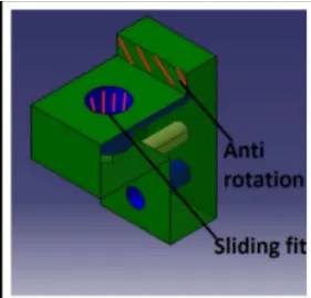
PIN RETAINER: It holds the pin against car panel.
What is the purpose of making a Rest unit & describe its parts?
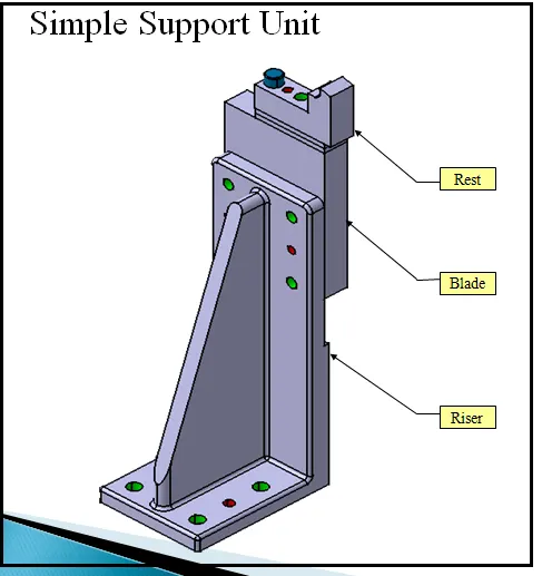
It is used to rest the components and parts on during the procedure. The rest block is adjusted to the precise specifications using the shim and spacer. The item is raised or lowered to the desired height using a common component called a riser.
The automobile panel is supported by a rest unit, which also resists the finger's clamping force using rest mylars and clamps the car panel as a result. Riser, shim packs, and rest mylars make up the rest unit. When creating a rest unit, holding force should be taken into account.
What are the basic fundamentals to design a Sensor unit?
The position and weight of parts and components are detected by this gadget. Only once the first operation is finished and a signal is sent will the second operation start. By doing this, accidents throughout the procedure will be avoided. Numerous sensor types, including proximity sensors, laser sensors, photoelectric sensors, and others, are used in the automotive sector. As the panels come together, each one that is loose should be felt. For optimal responsiveness on wide panels, sensors should be positioned diagonally and should be moveable in three dimensions.
What is a Rough locator unit & what are the basic fundamentals to consider while designing it?
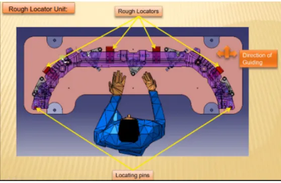
Its purpose is to direct the user in placing the automobile panel on the pins in the proper location. A rough locator may be a manufacture part or a standard part.
Fundamentals to keep in mind are:
a.It is positioned near the automobile panel's edge, where it must provide guidance.
b.It must be positioned with the edge of the car part at the same angle and at least 2 to 5 millimetres away from the edge.
c.Before the pin engagement process begins by 10 to 15 mm, it should begin guiding the panel.
d.It is made with an entrance angle for entering automobile parts.
e.The slots must face the direction in which the automobile part is guided.
What is a Base unit and describe it's parts?
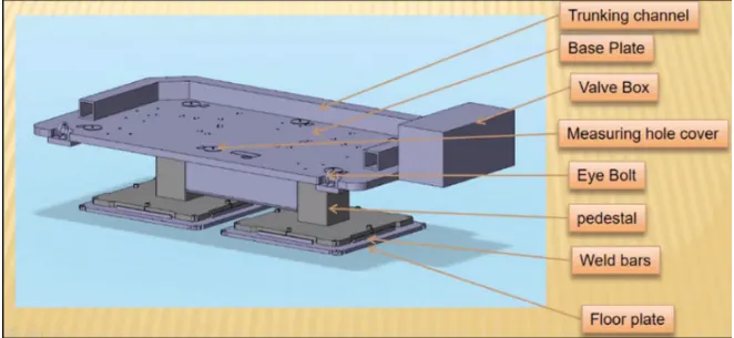
The base unit is used to mount all of the other components on during each procedure. Under its eyes, a bolt is used to lift or support the base, and a stool is used to add the necessary height. The base plate is mounted with the units/parts. Depending on whether it is a manual or robotic operation, its height should be chosen. For manual labour, the height should range from 850 to 1100 mm. Its designs ought to be vibration-free and low deflecting.
What is a Dump Unit and what are its functions?
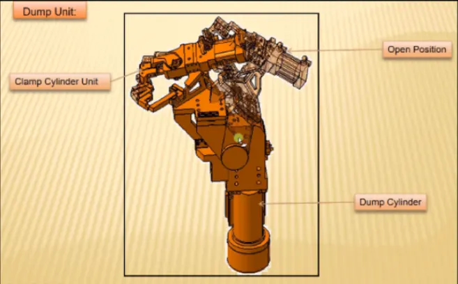
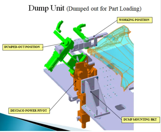
A complex machine with several moving parts is the dump unit. Due to the possibility of lasting mistakes caused by any design problem, we must proceed with the utmost caution when building a disposal unit.
When a straightforward unit cannot be fixed, it is used. The weight of the dump unit should be as low as feasible as this will help to reduce the force needed. It might have a lot of cylinders to carry out the challenging duty. Verify that the panel can be removed from the device while it is open.
What is a Slide unit? Mention where Slide units are commonly used.
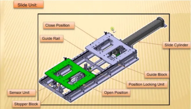
A clamp, a rest piece, and a pin are included in this package. By moving the component up, down, and forward and backward, it is used to carry out work. Once the job is finished, it can be quickly removed from the working area. The cylinder provides the necessary motion. To avoid any mishaps and guarantee that the objects are securely fastened, the sensor unit is also put at the end of the slide. It is used in locations with limited space and accessibility. The pull and push operations should be employed as infrequently as feasible. This is an important factor to take into account when the sliding unit is inclined.