Advanced Sheet Metal Design Using NX Cad Challenge_6_Bracket
1. Project Title: Bracket
2. Objective: To develop a model of a 'Bracket' in SIEMENS NX Sheet Metal Application using a '2D Drawing'.
3. Introduction: A bracket is any intermediary component in mechanical engineering that connects one part to another, generally bigger, part. A bracket is distinguished by the fact that it sits in the middle of the two and connects them. Brackets are often made up of two or more planes joined along one edge, and the simplest way to make them is to bend a flat object (such as a sheet of metal) in two or more locations. Sheet metal fabrication is one of the simplest and most cost-effective ways to create brackets, especially simple ones like angle brackets. Brackets are used to install a variety of products, including antennas, televisions, projectors, and street lights, among others.
Although brackets come in a variety of shapes and sizes, the most typical is an L-shaped bracket with the vertical half linked to a wall (or other major upright structure) and the horizontal section attached to a smaller object being mounted on the wall, such as a shelf. Brackets frequently have holes, either threaded or unthreaded, through which screws or other fasteners can be fed, although this is not a distinguishing feature of the bracket.
The majority of brackets are functional, with the goal of connecting and supporting items. Brackets, on the other hand, can be decorative: because they are frequently visible (for example, on shelves set above eye level), they may have cosmetic features and flourishes ranging from carefully machined decorative details to gold plating.
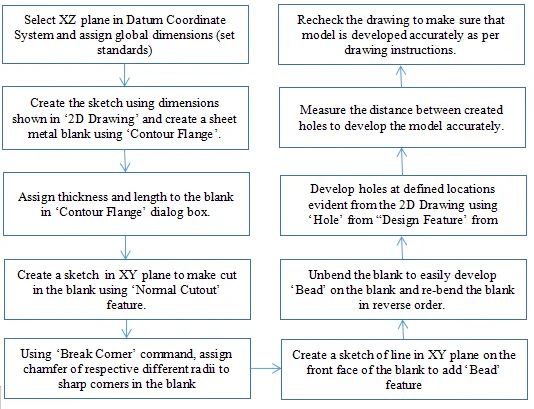
4. Design Methodology: Following flow chart illustrates the steps involved in modeling of the bracket from 2D Drawing.
5. Description: Following commands/features were used by me in developing the 3D model of a 'Bracket' using '2D Drawing'.
Mirror Feature: This feature was used to mirror half of the sketch (from 2D Drawing) to save time.
Contour Flange: This command is used when one needs to develop flange which follows the shape of a contour.
Normal Cutout: This feature enbales one to create cuts in the sheet metal blank after creatig sketch on the face of the blank of specific shape.
Break Corner: This is used to round the sharp corners/edges of the blank of given radius.
Unbend: It is used to flatten the bends of the blank after making one face stationary/fixed.
Bead: It is used to lift a certain area of the blank along defined contour and it simulates the stamping tool.
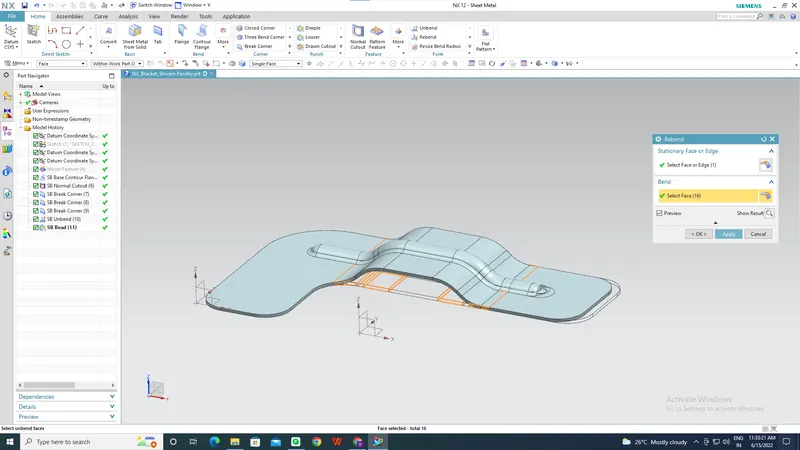
Rebend: This feature enables one to rebend the blank after generating dimples/beads in the reverse order in which unbending was done.
Hole: This feature can be found 'Menu-Insert-Design Feature- Hole' and it was used to create a simple through hole in the blank at specified loacations.
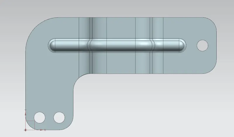
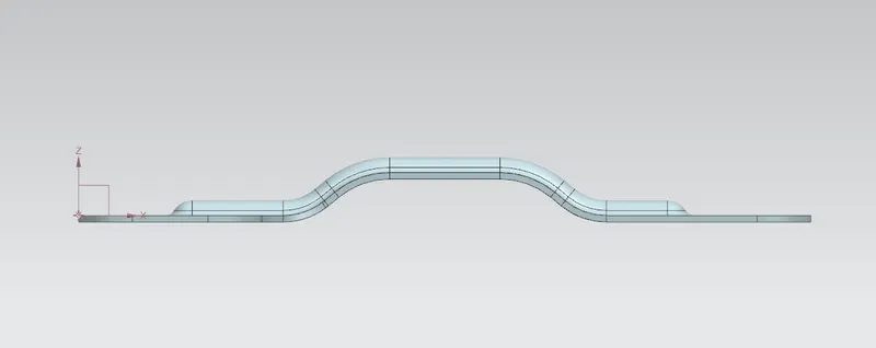
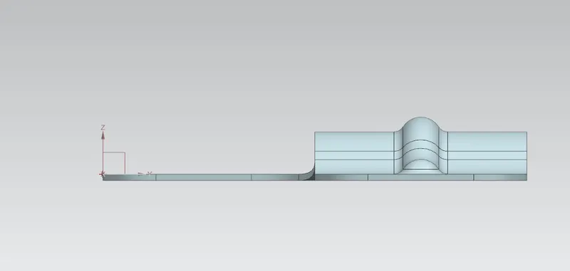
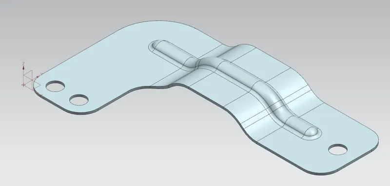
6. Snapshots of the 'Bracket' model
Top View
Front View
Side View
Isoemtric View
Rebend Feature
7 Conclusion:
SIEMENS NX sheet metal application is a handy CAD tool to develop model of complex arts such as brackets. I find the 'Unbend, Rebend, Dimple, Bead' features to be very flexible as one can develop any formed shape on any face of the sheet metal blank. This project has definitely brought a sense of understanding in me to use different features in NX CAD application.