Advanced Sheet Metal Design Using NX Cad Challenge_1_Casing Design
1. Project Title: CASING DESIGN
2. Objective:
Create a sheet metal Casing Design in the SIEMENS NX SheetMetal application and describe the stages involved in its development.
3. Introduction:
Sheet metal is a metal that has been produced into thin, flat slabs by an industrial process. Sheet metal is one of the most common metalworking materials, and it can be cut and bent into a wide range of shapes such as casing of an engine. Casings generally protect any machine part from environmental factors. Casings in case of compressors and turbines not only secure these vital engine parts, but also the pressurized air that generates energy to power the jet engine and push the plane through the air. Casings that are well-made are critical for efficient energy production and consumption while also lowering engine noise emissions. Accurate dimensional requirements is required to ensure that part assembly is securely sealed. Sheet Metal blank used in this project is of dimensions 60*50mm and 1mm thickness. Different commands have been used to bring the blank into desired shape and design.
4. Methodology:
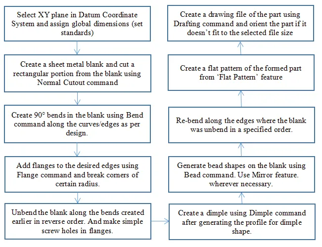
5. Description: Following tools/features have been used by me in developing the Casing Design on NX CAD.
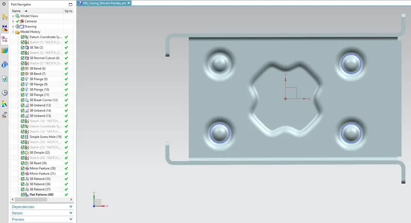
Tab: This feature is used to give thickness to the sheet metal blank. This is the very first command given in generating the case design.
Normal Cutout: This feature is used to cutout certain part of the blank by sketching a curve on one of the faces of the blank.
Bend: Bend command is used to bend the blank along a length sketched on the blank.
Flange: This feature comes very hand if one have to add bends at edges at any angle and lengths.
Break Corner: This is used to give chamfers to sharp corners of the flanges.
DATUM CSYS: This tool is used to create sketch at certain distance from some plane/edge/ponit to get a desired feature in the part.
Hole: This feature is used to create holes of desired types that can be accessed from the 'Design Feature' in 'Insert' from 'Menu' tool.
Dimple: This tool is used to lift certain area of the part 'inside' a sketch according to stamping tool.
Bead: This lifts a certain area of the model along a defined contour and simulates accroding to stamping tool.
Mirror: This feature is used to generate same feature in the model and reduces the need of creating sketch again and again for a certain feature.
Rebend: The command is used to rebend the blank along the edges/faces in reverse order in which the bends were created.
Flat Pattern: This feature is used to create a flat pattern of the formed sheet metal part as if it has been flattened out on a plane.
6. Different Views of the Model:
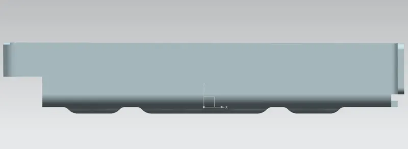
Front View:
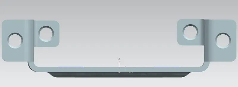
Side View:
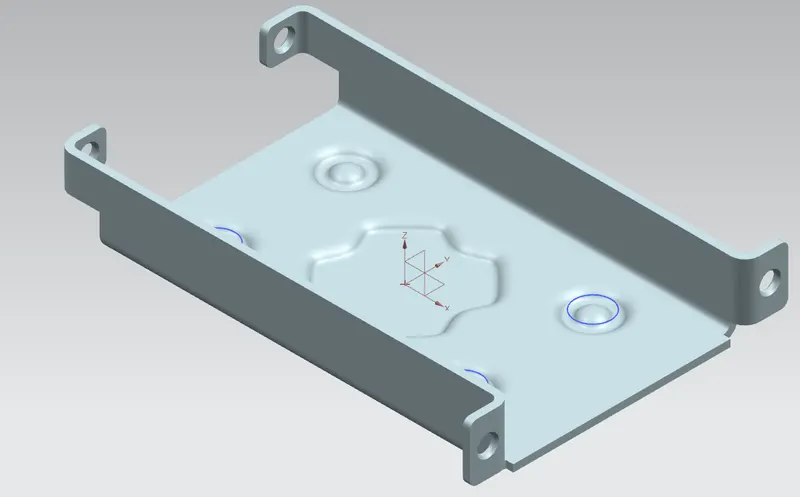
Isometric View:
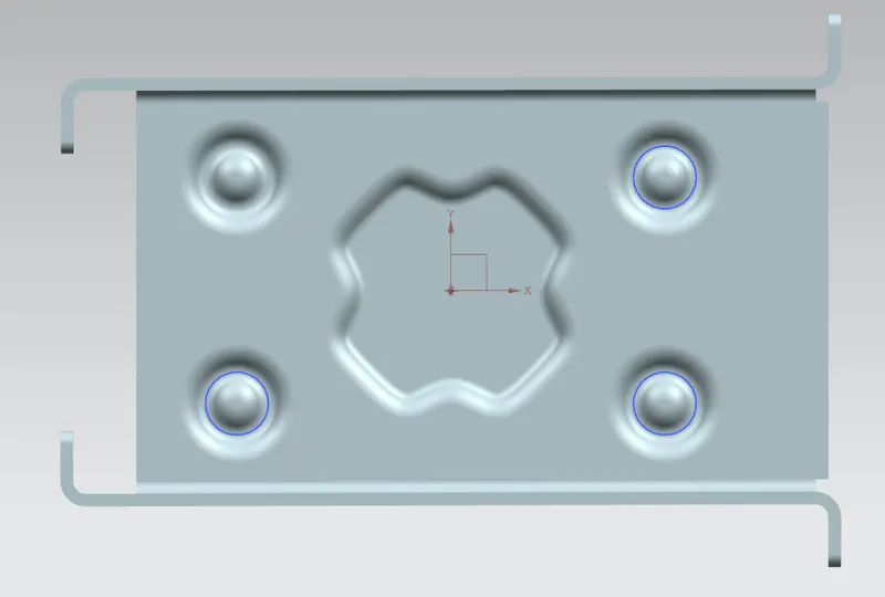
Top View:
Part Navigator showing different tools/features used in designing:
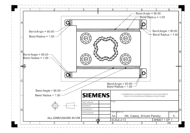
7. Drawing Sheet Image:
8 Conclusion:
Different types of impressions can be fromed on sheet metal blank with complex contours which is not an easy task. Flanges can be easily generated along edges which saves time as compared to extrude command. I ws able to understand different features such as flat pattern, mirror, offset planes, annotations in the drawing as well.