Week 3:- BiW Fixture Design Methodologies Challenges
Question 1. What is Design Methodology?
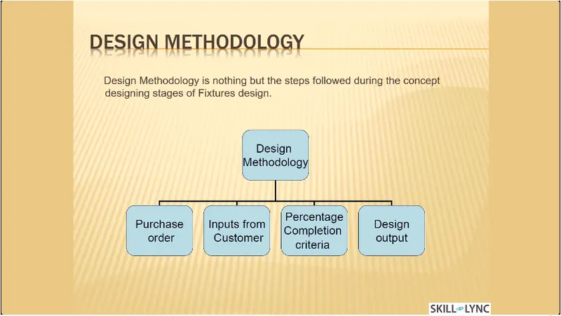
Answer 1. Design methodologies are the steps followed during the concept designing stages of fixture design. The various stages of design methodologies are-
- Purchase order
- Inputs from customer
- Percentage of completion criteria
- Design output
- Purchase Order-
A purchase order (PO) is a commercial document and first official offer issued by a buyer to a seller indicating types, quantities and agreed prices for products or services. It is used to control the purchasing of products and services from external suppliers. Purchase orders can be an essential part of enterprise resource planning system orders. Purchase order is a order from customer for start of the work. After offer has been finalized customer will be releasing the LOI/PO(Purchase Order).
Once PO is released we have to start the work.
After PO from the customer, we have to prepare the schedule.
Purchase order is the confirmation document from customer to proceed the committed work for them.
- Inputs from customer-
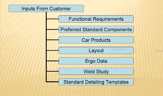
The inputs from the customers are as below-
Functional Requirements- The purpose or the function of the fixture will be given as inputs from the customers like what are the process the fixture is going to do i.e welding, hemming, riveting, gluing or whether it is a checking fixture, storage racks, etc.
Preferred Standard Components- As we know different companies follow different standards, we will be following the standards followed by the customers. By following standards the time of designing and manufacturing of parts will be saved, which will be automatically minimizing the time of the projects. As for the standards parts, it can be easily replaced from the used fixture to the new fixture which reduce the cost.
This includes parts which are already available at customer side or standard parts provided from customer. Also by which standards the part should be manufactured, standards like ABB, NAAMS, DESTACO, ZYTRAN and TUNKERS. Standard parts like clamps, cylinders, risers, pins, L-blocks, retainers, etc.
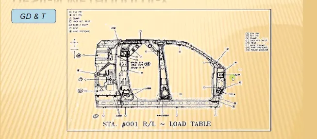
Car products- The inputs we get from car products are GD&T, part list, cad files of car part, clamp plan, product assembly process sheet.
GD&T Provides information of-
- Locating Pins, Rest, Clamp, Dumps & Slide information of each station.
- Sequence of opening of clamps, dumps and slide stroke information.
Layout- Layout shows the entire assembly plan to understand the process. Layout provides the information of flow of parts, station pitch, robot stations, accessories like tool changers & tip dressers, sub assembly links, plat form height, loading/unloading sequence/height.
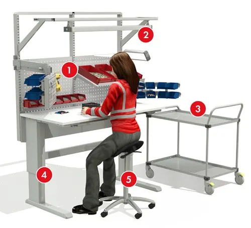
Ergo Data- Ergonomics refers to the study of human behaviour and movements. The ergo data is mainly used to make the operator comfortable which may lead to improve the efficiency in cycle time & production. Ergo data provides inputs like platform height, maximum & minimum reach from operator to fixture, maximum & minimum height of the fixture, whether the child parts/assemblies are visible while clamping or loading & unloading. Also provises information like loading height, working safety zone of operator, etc.
Weld study- Weld study is the important inputs given by the customer. It gives details about the study of particulars gun that we use for welding. Also the dates like number of weld, position of weld in the components will be given. In short, weld study includes weld gun details, weld matrix & weld points.
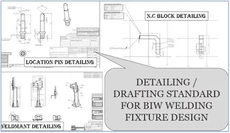
Standard detailing templates- This inputs include the detailing templates of 2D cad drawing as per the customer standards. So, we have to follow the detailing templates as per the customer standards.
- Percentage of completion criteria-
It is followed in the designing stages & dispatch stages of welding fixtures.
It helps to track or identify how much task completed & how much to go further for completing a fixture.
Inputs & concept design – 0 to 25%
Concept approval & simulation check – 25 to 40%
Design freezing & detailing – 40 to 85%
Check & final dispatch – 85 to 100%
The above mentioned percentage are the percentages of stage wise completion criteria of the projects.
- Design Output-
The output is 3D models and the 2D drawings of the tools which includes key sheets & layout sheets for unitized tool where as no need of key sheets for non-unitized tool.
Unitised tools- (multiple units on a common base) require two types of drawing sheets.
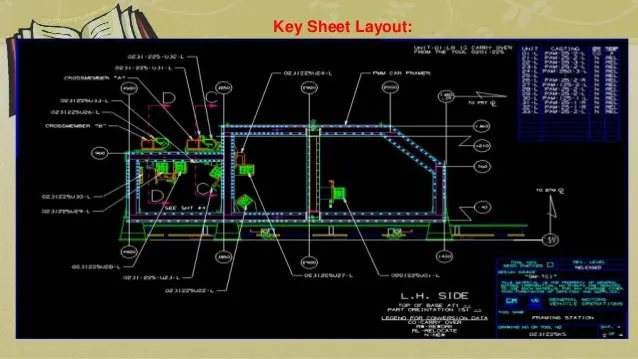
- Key sheet- An index of units and their placements on the tool base.
- Layout Sheet- A detailed drawing of individual units to include all of their component.
Non-unitised tool- Tools that can stand alone and can be detailed completely on a layout sheet.
Question 2. What are the inputs required from the customer to start designing a Fixture?
Answer 2. The inputs required from the customer to start designing a fixture are as follows-
- Fundamental requirements
- Preferred standard components
- Car products
- Layout
- Ergo data
- Weld study
- Standard detailing templates
- Functional Requirements-
The purpose or the function of the fixture will be given as inputs from the customers like what are the process the fixture is going to do i.e welding(spot or seam weld), gluing, riveting, hemming or whether it is a checking fixture or a storage racks etc.
It is one of the basic requirements to get from the customer to start designing a fixture.
- Preferred standard components-
As we know different companies follow different standards, we will be following the standards, we will be following the standards followed by the customers. By following standards the time of designing and manufacturing of parts will be saved, which will be automatically minimizing the time of the projects.
As for the standards parts, it can be easily replaced from the used fixture to the new fixture which reduce the cost.
Some of the preferred standard components used in BIW fixtures are given below,
- Standard like ABB, NAAMS, DESTACO, ZYTRAN, TUNKERS are used in design & manufacturing of fixtures.
- Standard parts like Risers, L-blocks, retainers, pins, NC blocks, Shims, etc.
- Components like clamps, cylinders, slides, switches, sensors, etc.
- Weld guns, Tip dressers, Tool changers, etc. tip dressers are to sharpen the tip of the tools whereas tool changes are used in robots to do various process. As robots are too costly, tool changers are used.
ABB – It is a Robots manufacturing company
ABB robots have automated many applications involved with the manufacturing of cars. Their material handling robots have been implemented for part loading, unloading, and transfer processes. Cars need to be built with strong and durable materials and parts, which are often too heavy to be handled by workers. ABB’s IRB 6640 and IRB 7600 are two of their heavy-duty material handling robots designed to handle large payloads with ease and are common choices amongst automotive manufacturers. These robots can make quick work of loading and unloading large metal sheets from machine presses used for form car doors, pillars, hoods, and roofs.

- Car Products-
The inputs we get from car products are: GD&T, part list, Cad files of car part, Clamp plan, product assembly process sheet.
GD&T- It provides information of locating pins, rest, clamp, damp & slide unit informationof each station. Also includes the information of sequence of openings of clamps, dumps & slide stroke information.
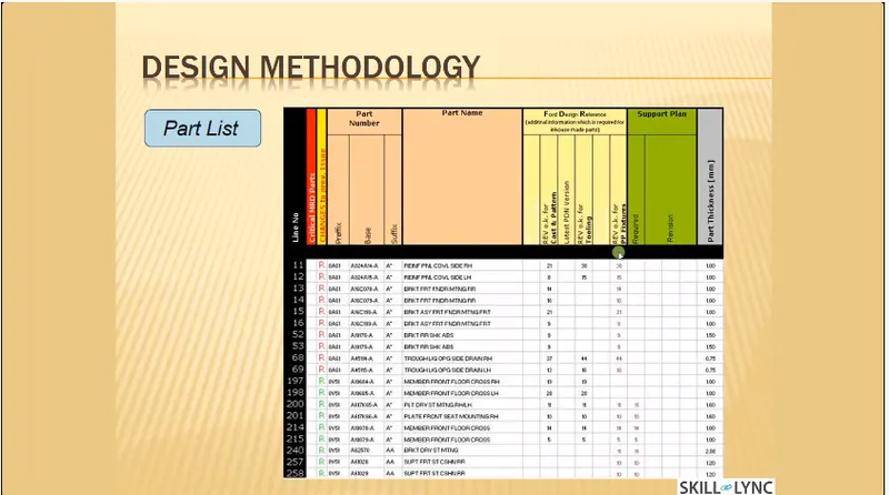
Part lists- It gives the lists of parts which are going to assembled in the fixture. The list contains the information of part number, part name, revision of fixture, part thickness, etc.
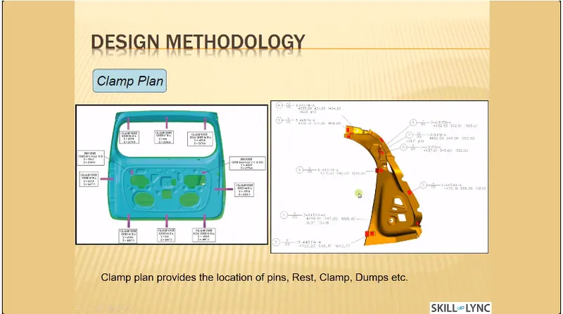
Clamp plan- Clamp plan provides the information of location of pins, Rest units, clamp unit, dump etc. It is the important input from customer. The clamp plan/position should not be changed without the knowledge of customer.
3D cad file- The 3D model of the car part will be given from customer. From that 3D model we will be developing our fixture design process. The 3D cad file will be in the format of step file (stp) or IGES file (igs).
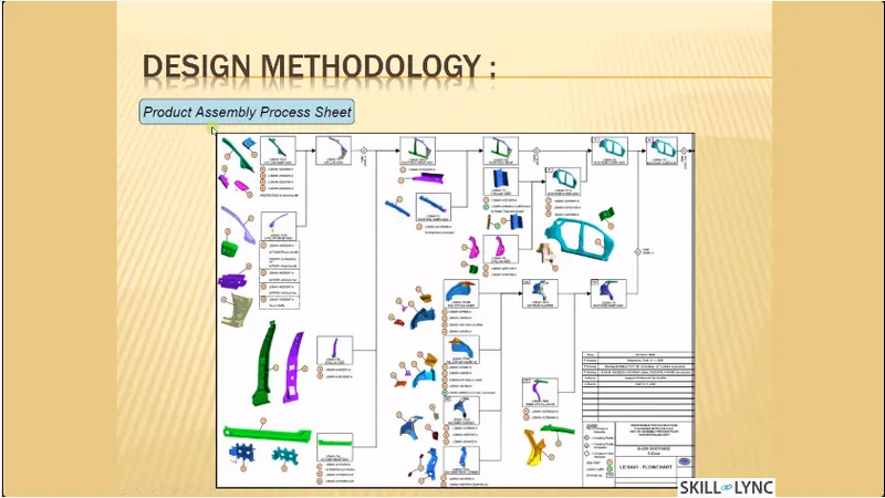
Product assembly process sheet- It gives the information of stage wise assembly process like how the parts move from one assembly process like how the parts move from one assembly station to other after the completion of joining process.
- Layouts-
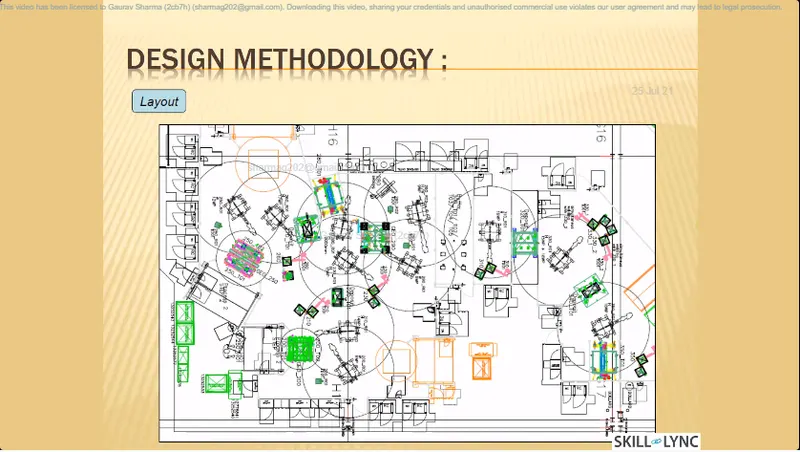
Layout shows the entire assembly plan to understand the process.
Layout provides the information of flow of parts, station pitch, robot stations, accessories like tool changers & tip dressers, sub assembly links, plan form height, loading/unloading sequence/height.
- Ergo Data-
As same as preferred standards, different companies follow different standards of ergo data.
We have to follow the customer standards of ergo data.
The inputs of ergo data will given by the customer mostly in case of manually operated fixtures/manual fixtures.
The ergo data is mainly used to make the operator comfortable which may leads to improve the efficiency in cycle time & production.
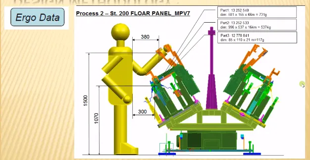
Ergo data provides inputs like platform height, maximum & minimum reach from operator to fixture, maximum & minimum height of the fixture, whether the child parts/assemblies are visible while clamping or loading & unloading.
Also provides informations like loading height, working safety zone of operator, etc.
- Weld Study-
Weld study is the important inputs given by the customer. It gives details about the study of particular gun that we use for welding.
Also the data like number of weld, position of weld in the components will be given.
In short, weld study includes weld gun details, weld matrix & weld points.
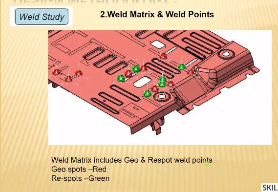
Generally weld points will be given in spheres.
- Standard detailing templates-
This inputs include the detailing of 2D cad drawing as per the customer standarrds.
So we have to follow the detailing templates as per the customer standards.
Question 3. What is the input we get from "Car Products"?
Answer 3. Inputs we get from car products includes-
- GD&T
- Part lists
- 3D cad file
- Clamp plan
- Product assembly process sheet
GD&T-
GD&T – Geometric Dimensioning & Tolerance.
It provides information of locating pins, rest, clamp, damp & slide unit information of each station.
Also includes the information of sequence of openings of clamps, dumps & slide stroke information.
Tolerance important-
Assemblies – Parts will often fit together if their dimensions do not fall with in a certain range of values.
Interchangeability – If a replacement part is used, it must be a duplicate of the original part within certain limits of deviation.
The relationship between functionality and size or shape of an object varies from part to part.
- Part lists-
It gives the lists of parts which are going to assembled in the fixture.
The list contains the information of part number, part name, revision of fixture, part thickness, etc.
- 3D cad files-
The 3D model of the car part will be given from customer. From that 3D model we will be developing our fixture design process.
The 3D cad file will be in the format of step file (stp.) or IGES file (igs.) or sometimes it may be in part file (prt.).
- Clamp plan-
Clamp plan provides the information of location of pins, rest units, clamp unit, dump, etc.
It is the important input from customer. The clamp plan/position should not be changed without the knowledge of customers.
It gives the detail of the exact position of the clamping units.
- Product assembly process sheet-
It gives the information of stage wise assembly process like how the parts move from one assembly to other after the completion of joining process
It shows the sequence of operations/process to be done in a part or a panel.
Also what are the parts to be joined with the panel will shown in sequence.
From this sheet we can trace out the pending process which has to further go on for completion of part.
From this product assembly process sheet designer can understand the sequence for designing the fixtures.
Question 4. What is the Clamp plan?
Answer 4. A clamp is a fastening device used to hold or secure objects tightly together to prevent movement or separation through the application of inward pressure.
Essential requirements of clamps-
All clamps must fulfill four essential requirements. They are-
- The work piece must be held rigid while undergoing operations.
- The time required for loading / unloading the tool must be as short as possible, which means the clamping device must be quick acting.
- when subjected to vibration, chattered, heavy pressure the clamping must be positive.
- The clamp must not damage the work piece.
CLAMP PLAN-
Clamp plan provides the information of location of pins, rest units, clamp unit, dump etc.
It is the important input from customer. The clamp plan/position should not be changed without the knowledge of customer.
It gives the detail of the exact position of the clamping units by mentioning a co-ordinates in the particular position.
Question 5.What is the purpose of a Layout?
Answer 5. The purpose of the layout is to understand the information about where the fixture & robots are placed, working area covered by the robot, what are the fixtures assigned for the robots to do the process, etc. layout shows the entire assembly plan to understand the process.
The circle around the robot is the swept area of the particular robot which shows the reachability of the robots particularly with the confine circle.
Layout provides the information of flow of parts, station pitch, robot stations, accessories like tool changers & tip dressers, sub assembly links, plat form height, loading/unloading sequence/height.
Flow of parts- It shows the flow of the parts/panel in the assembly line or shop floor like how component move from one station to other station after the completion of process.
Station pitch- The distance between two stations is known as station pitch. It shows the space constraints between the two stations, which shows in layout.
Robot stations- It shows the position where the robots and their accessories placed, which is shown in the layout.
Sub assembly link: Sub assembly link is the link between the assembly fixtures & the main assembly line. It shows that how the sub assembly fixtures are linked with the main assembly line.
The main purpose of the layout is to understand the entire plan of the assembly line.
The layout providing the above information like flow of parts, station pitch, robot stations, etc used to understand the working process of robots, what are the fixtures assigned for the robots, space constraint, etc.
By considering the layout, the designers can develop the concept sketches of fixtures without any clash in the assembly lines.
One of the main purpose is to get the information about the space constraint which helps to develop the robotic cell without any clash during working.
Question 6. What is Ergo data?
Answer 6. Ergo data is the data or inputs which gives the human factors engineering data, between the operator and his working environment. Before detailing about ergo data we should know about ergonomics in detail.
ERGONOMICS-
Ergonomics also known as human engineering & human factors engineering is the scientific study of the relationship between man and his working environments.
OBJECTIVES OF ERGONOMICS-
The fundamental objective of the study of ergonomics is to optimize the integration of man & machine, so as to improve the productivity & accuracy.
In short, the objective of ergonomics is designing for human use and optimize working & living condition.
Two main objectives of ergonomics are-
- To enhance the efficiency and effectiveness with which the work is carried out so as to increase the convenience of use, reduced errors & increase in productivity.
- To enhance certain desirable human values including safety, reduced stress and fatigue and improved quality of life.
Ergonomics involves the design-
- A work place suitable for the worker.
- Machinery & controls, so as to minimize physical strain on the worker to enable the improvement in the efficiency.
- An environment for performing a task most effectively and conducive.
- A conducive task & work organization.
Benefits of Ergonomics-
Improved working condition.
Reduce physical workload.
Improved work postures.
Reduced efforts of certain movements.
Better reading instrument displays, handling of machine levers & Controls.
Reduced unnecessary information recall efforts.
Below, I have given a basic example of ergonomics in the workstation.
ERGO DATA-
Ergo data is the data or inputs which gives the human factors engineering data, between the operator & his working environment.
Ergo data is mostly needed while there is a need of manual operator/operation.
Ergo data will be given from customer as per their standard. Every customers follow different ergo data standards.
As per customer standards, we have to consider the ergonomics in the fixture while designing.
From ergo data we get the details or inputs related between the operator and his working fixture.
The ergo data is mainly used to make the operator comfortable which may leads to improve the efficiency in cycle time & production.
Question 7. What do you understand by Weld study?
Answer 7. Weld study is the important inputs from the customer.
It gives the study of particular gun that we use for weld, No. of spots to be welded, sequence of weld, position of weld in the components.
In short, weld study includes weld gun details, weld matrix & weld points.
Generally the weld points will be given in spheres.
Red sphere represents the Geo spot weld points whereas
Green sphere represents the Respot weld points.
The weld points are classified as,
- Geo weld points-
The Geo weld points are which is planned in the Geo fixture.
These weld will determine the position of the panels as per the given data in drawing.
The geo weld points are represents in red sphere in the weld study inputs given by the customers.
- Respot weld points-
The respot weld points are planned in the respot tool.
These weld will determine the strength/stiffness of the panel/components.
The Respot weld points are represent in green spheres in the weld study inputs given by the customers.
Question 8. What are the criteria for percentage completion in the designing stage? Explain it in detail.
Answer 8. The percentage completion criteria is followed in the designing stages & dispatch stages of welding fixtures.
This percentage completion criteria is followed to trace the project whether it matches the committed date given to the customer for hand over the projects to them.
Also it helps us to identify the stages in the projects like how much the project is completed and what are the further stages are in pending, to complete which helps us to complete the projects on the committed time and date.
The percentage completion criteria is divided into four stages to identify the percentage of the completion of work.
The four stages of percentage completion criteria are as follows-
- Input & concept design
- Concept approval & simulation check
- Design freezing & detailing
- Check & final dispatch
- Input & concept design- If the project is in the stage of Input & concept design then the percentage completion criteria of the project will be between 0 – 25%.
After the completion of input & concept design then the project will be moved to concept approval & simulation check which is the second stage in percentage completion criteria.
- Concept approval & simulation check- If the project is in the stage of concept approval & simulation check then the percentage completion criteria of the project will be between 25% - 40%.
After the completion of concept approval & simulation check then the project will be moved to design freezing & detailing which is the third stage in percentage completion criteria.
- Design freezing & Detailing- If the project is in the stage of Design freezing & detailing then the percentage completion criteria of the project will be between 40% - 85%.
After the completion of design freezing & detailing then the project will be moved tp check & final dispatch which the fourth & the last stage in percentage completion criteria.
- Check and final dispatch- If the projects is in the stage of check & final dispatch then the percentage completion criteria of the project will be between 85% - 100%.
After the check the project will be finally dispatched successfully to the customer.
Question 9. Brief about "Output" in design?
Answer 9. OUTPUT IN DESIGN-
The output is 3D models and the 2D drawings of the tools.
For unitized tools (multiple unit in a common base) requires two types of drawing sheets.
Example of the unitized tool: a tool with multiple unites like rest unit, clamp unit, sensor unit ,etc. in a common base
The two types of drawing sheets are-
- key sheet
- Layout sheet
Key sheet-
key sheets gives or shows the index of unit & their placements on the tool base.
It will have an orthogonal view of the fixtures including a numbered balloon drawing mentioning the units.
Layout sheet-
Layout sheets shows as detail drawing of individual unites to include all of components.
For the Non unitized tool no need of key sheets. As they can stand alone, the drawing can be detailed completely on a layout sheets.
THE DESIGN OUTPUT SHOULD COMPILE FOLLOWING POINTS:
- Approved standard components are to be used wherever possible.
- Design must be as simple & economics as possible.
- Design must be comply with all current safety & ergonomic requirements.
- Design must provide for controlled & damage free handling of product.
- Adequate error proofing provision must be incorporated into each design by proving proximity switches, rough locators, etc.
- The weight of the moving parts must be kept to a minimum while maintaining maximum strength.
- Frames & structures are to be simple & study.
- Design clearance & accessibility for routine maintenance & service.
- Motion control must be considered on any moving equipments.
- Designer is responsible to validate clamps & weld guns.
Question 10. What do you understand by structuring a design tree? How does it reduce errors during the design process?
Answer 10. Structuring a design tree implies to process where all the assemblies & parts are named in a specific standard. Different customers have different set of standards to structure a design tree.
It is an important process which helps us to identify a specific part or assembly as to which project, tool/unit, it belongs to.
This helps us to avoid the errors during design, manufacturing, assembly, inspection, etc.
If the parts or assemblies are not named properly or the design tree is not structured properly, it will create confusion to understand the design & may create major possibilities of making an error.
Naming of a fixture or a unit or a part, gives the information as to which project or zone or assembly do they belong.
It can help us to identify the quantity of items of same types or different types that are being used in the assembly.
While start designing a fixture, the first unit will be the base unit.
In structure tree all the manufacturing parts should be first and the standard parts should be at the last.
Structure tree helps to study or understand the parts in the assemblies easily.
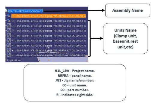
Steps to structuring a design tree:
Step 1: Create new à Product à click OK (by clicking ok now you will enter into a product window)
Step 2: Then right click product in a structure tree à go to properties à rename in part number (As we created a product we have to mention the total assembly name of the fixture) à click ok.
The naming of the assemblies / parts / units have certain standard procedures, which I have clearly explained below.
The product name is title of the fixture. The renamed titled should be à P001_Z03_ST09_00_00_R
P001 – represent the project name.
Z03 – Zone name.
Panel name will also be mentioned in some case.
ST 09 – Station name / J03 – Jig name will be mention sometimes.
00 – unit name.
00 – Part number.
R/L – is representing the right hand side / left hand side of the panel.
The other renamed title explained in video is
H1L_19A_RRFRA_JG3_00_00_R.
H1L_19A – Project name.
RRFRA – Panel name.
JG3 – Jig name/number.
00 – unit name
00 – Part number.
R – Indicates right side.
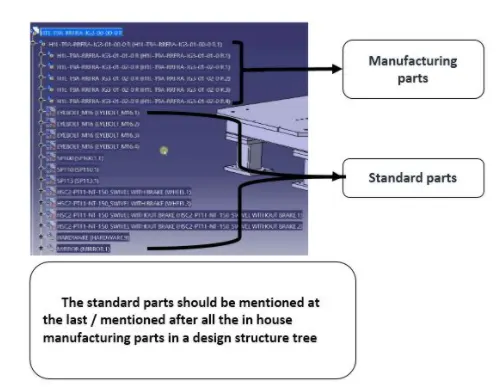
Design tree structure (showing procedure of positioning the manufacturing & standard parts in a design tree)`uarr`
Question 11. What are Units? Mention 5 types of units.
Answer 11. A unit is a device that has a specified function, especially one forming part of a complex mechanism.
A welding fixture is assembly of different types of units.
As name refers, the different units will be only seen in the unitized tool.
A units are classified into two, they are,
Simple unit- In a simple welding fixture, the combination of these different units will be seen.
- Rest unit.
- Fixed pin units.
- Retract pin units.
- Rough locator unit.
- Sensor unit.
- Base unit.
Complex unit- In a complex welding fixture, in addition with some of the simple units these complex units will also seen
- Slide unit.
- Dump unit.
Below I have mentioned some 5types of units.
SOME FIVE TYPES OF UNITS-
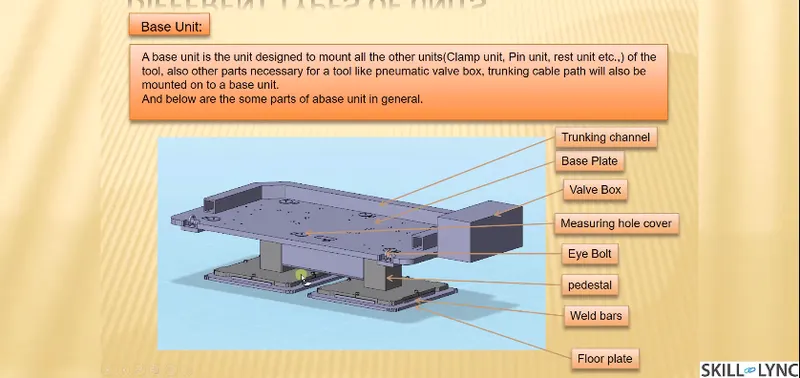
- Base unit-
Base unit is the unit designed to mount all other units such as clamp unit, pin unit, rest unit etc., of tool, also other parts necessary for a tool like pneumatic valve box, trunk cable path will also be mounted on to be a base unit.
2. Fixed pin unit-
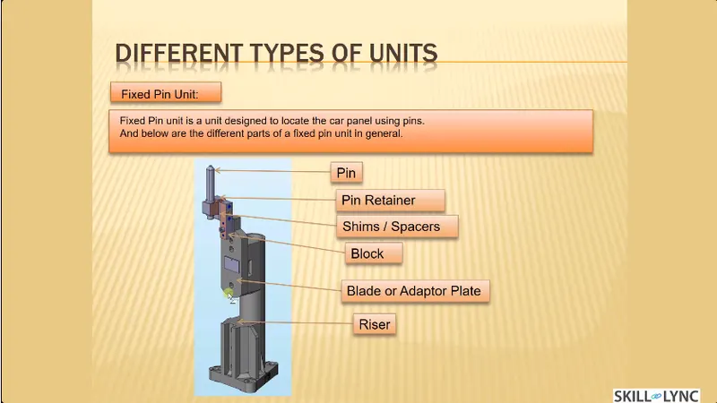
Fixed pin unit is a unit designed to locate the car panel using pins.table
Pin, pin retainer, shims, blocks, blade, riser are the part of fixed pin units.
Pin retainer is used to hold the pin firmly.
Typically, the locating pins are used to locate a body part in a position sufficiently accurate to execute a welding process.
The body part is constrained by a set of appropriately locating pin so total constraint by locating pin should be fully constrained at all times to prevent any movement.
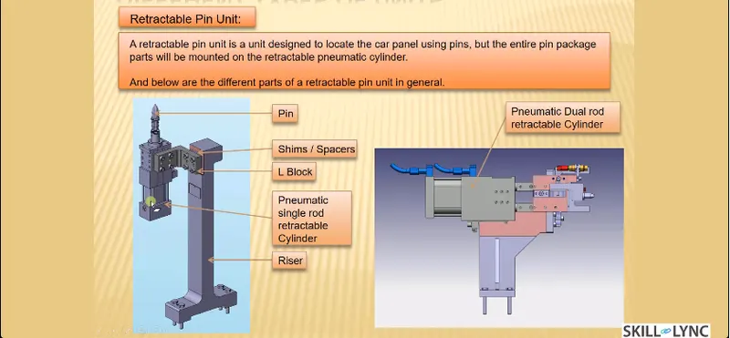
3. Retractable pin unit-
retractable pin unit is unit designed to locate the car panel using pins, but the entire pin package parts will be mounted on the retractable pneumatic cylinder as shown in below fig 3.
Retractable pin unit is the opposite of fixed pin unit which can be moved up & down also which can be retracted till certain distance.
It is mainly used for unloading the complex panel after welding.
- Clamping unit:
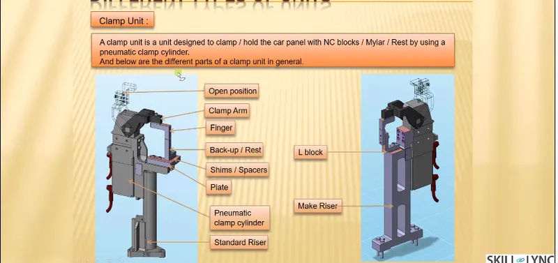
Clamp unit is a unit designed to clamp or hold the car panel with NC block / Mylars by using a pneumatic clamp cylinder.
Clamping unit is used to clamp the part which is to be welded after location using pin unit.
Clamping is achieved with the help of pneumatic cylinders and clamp arms.
Clamping arm, finger, rest, shims, standard riser, pneumatic cylinder are the parts of clamping unit in general.
- Slide unit:
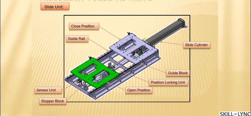
Slide unit is found mostly in complex fixture, where the sliding mechanism will be involved.
This type of unit used when there is some space constraints.
Guide block, guide rail, position lock unit, stopper block, sensors are the parts of slide unit in general.
Guide block & guide rail helps to the guide the slide unit. The rail should always be covered to protect against weld spatter & dust by a bellow or a sheet metal cover.
Position lock unit helps the slide to be locked/clamped in the working position.
Stopper block helps to stop/control the entire moving of a slide unit from certain distance, which is placed at the end of the guide rail.
Sensors – The two end limits to be sensed externally by a proximity sensor.
Question 12. Describe Fixed Pin units & their purpose?
Answer 12. Fixed pin unit is a unit design to locate the car panel using pins.
Pin, pin retainer, shims, blocks, blade, riser are part of fixed pin unites in general.
Pin retainer is used to hold the pin firmly.
PURPOSE OF FIXED PIN UNIT-
As by 3-2-1 locating principle, the introduction of two pins helps to arrest the 6 degrees of freedom (4 axial & 2 radial movements) whereas other 6 degrees of freedom are arrested by introducing minimum three supports.
Typically, the locating pins are used to locate a body part in a position sufficiently accurate to execute a welding process a welding process.
The body part is constrained by a set of appropriately locating pin so total constraint by locating pin should be fully constrained at all times to prevent any movement.
Question 13. What are the different parts of a fixed unit?
Answer 13. The different parts of the fixed pin units are as follows-
- Pin
- Pin retainer.
- Shims
- Blade
- Riser
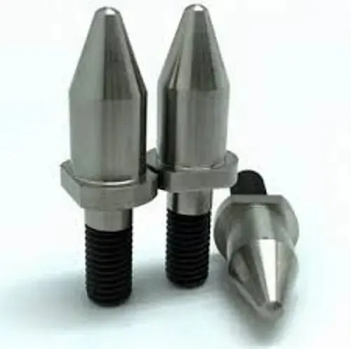
- Pin- It is used for the location purpose of the panel.
Typically, the locating pins are used to locate a body part in a position sufficiently accurate to execute a welding process.
The body part is constrained by a set of appropriately locating pin so total constraint by locating pin should be fully constrained at all times to prevent any movement.
There are dozens of styles of locating pins that can be utilized in a design. Below I have shown the commonly used pin.
- Pin retainer- Pin retainer is used to hold the locating pins firmly.
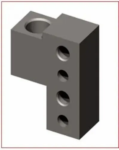
- Shims- In general, a shim is a thin and often tapered or wedged piece of material, used to fill small gaps or spaces between objects.
Shims are typically used in order to support, adjust for better fit, or provide a level surface.
Shims may also be used as spacers to fill gaps between parts subject to wear.
Shims are the small parts which comes with the thickness of 0.1mm, 0.2mm, 0.5mm, 1.0mm etc.
These will compensate the stack up tolerance which reflects at the mylars.
We give tolerances to all parts of the fixture. Due to this tolerance the mylars will either lift up moves down from its defined position.
To adjust the mylars for getting the defined position we use shims.
Shims will be added above the mylar for adjusting according to tolerance.
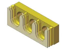
Types of shim-
- Wood shim
- Stone shim
- Plastic shim
- Metal shim
- Paper shim
- Riser:
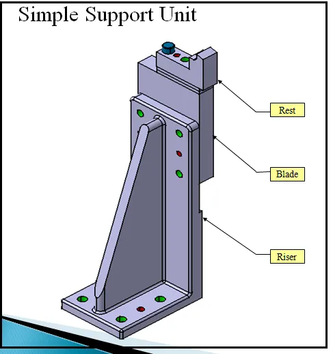
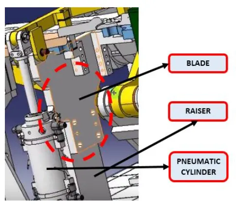
Riser is a manufacturing part used to raise / height the assemblies of fixture.
One end of the raiser will be attached to the blade.
Raiser can be of two types. They are,
- ‘L’ type risers.
- Square tube risers.
1. L TYPE RISERS: L type risers are of welded type. Where the stiffner will be added at the centre for support, as shown in the below figure the wedge shaped structure is known as stiffner which is used as a support/to withstand load.
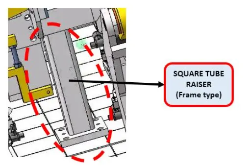
2. Square tube risers: Square tube risers are of frame type.
- Blade- Blade are the plates which are attached to raiser.
Blade is also attached or mounted with cylinders, arms etc.
Question 14. What is the purpose of making a Rest unit & describe its parts?
Answer 14. REST UNIT
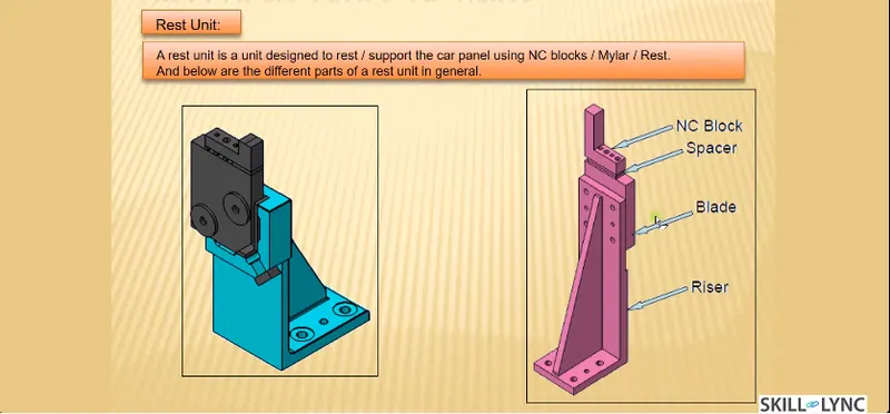
- Rest unit is designed to support car panel using Myler/NC block/rest component is rested only, no upper clamp or force applied there.
- The rest unit are designed to rest/ support the car panel by using NC blcoks/Mylars/rest.
- It is the simplest unit to design because it have less parts to design & the purpose is only resting of the panel.
- Because of this simplicity the rest unit is combined with other unit to reduce the cost of overall project.
- It can be combined with clamp unit as well to rest the car panel. It can be combined with locating unit to locate as well as to rest the car panel, also locating ,clamping & rest unit can be combined together in one unit to reduce cost.
- The combined locating, clamping & resting unit to reduce the cost.
Parts of the rest unit-
- Riser -
- Riser is a structure generally used to mount the toggle clamp and rest, clamp mylars and location pin.
- It is not necessary to have one riser where all the parts of clamp or rest or location units are mounted.
- Generally risers are either made of plate fabrication or plate and tube welding together or from single gas cut plate.
- These are generally manufactured to give height to the assembly.
- Blades-
- Blades are the plates attached to the riser. Parts like cylinders, arms,etc., are mounted on the blade.
- Chamfer is done to straighten the blade.
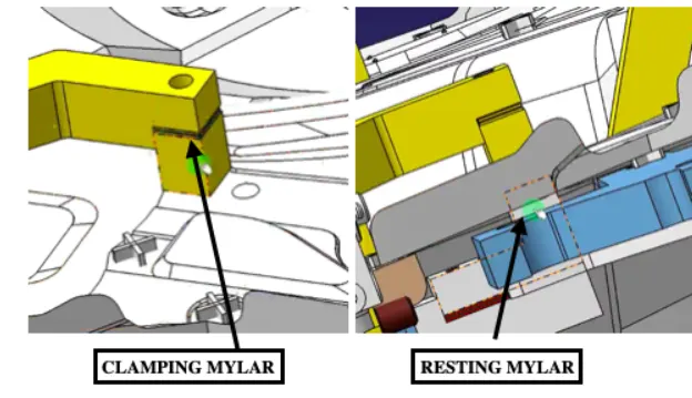
- NC blocks/Mylars-
- Mylars are the part which are holding the panel from the top & bottom. It is a jaw type, during welding it wont deform from its position.
- It is also known as fingers. It wont allow deformation of the part due to welding stresses.
- Mylars are of 2 types,
- Clamping mylars
- Resting mylars
- Only resting mylars are seen in resting unit.The panel which rests on the part is known as resting mylars.
- Shims/Spacers-
- Metal shims are used to finely adjust the location of how the fixture holds the part so that it is welded together within the dimensions set for the product to work well.
- A pack of thin metal shim is placed between two components in the fixture
Question 15. What are the basic fundamentals to design a Sensor unit?
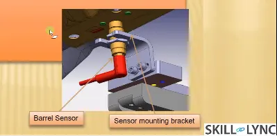
Answer 15. Sensor Unit- A sensor unit is a unit designed to sense car panel using electrical sensor is called sensor unit. The signal from the sensor is send to the PLC (Programmeable Logic Controller) so the next process is executed by this signal.
- A sensor is a device that measures physical input from its environment and converts it into data that can be interpreted by either a human or a machine.
- Most sensors are electronic(the data is converted into electronic data), but some are more simple such as glass thermometer, which presents visual data.
- Peope use sensors to measure temperature, gauge distance, detect smoke, regulate pressure and other uses.
- The sensor is very sensitive & easily damagable part so sensor cover is provided to the sensor for safety purpose.
- There are different types of sensors like:
- Proximity sensor
- Laser sensor
- Photo electric sensor
- Infrared sensor
Fundamentals of sensor unit-
- Every Loose panel which are being welded by tools should be sensed.
- The assembly of the car panel consists of nmber of panels. The location of every panel is fixed.There are some locating units, clamping unit, rest unit,etc., are provided for proper location and operation. To conform the presence of the part sensors are attached to the units.
- Each panel should be sensed by 1 to 2 sensors depends on the size of panel, preferred to be in diagonal opposite ends of panel.
- Sensor is used to sense the part is loaded or not & starts the operation by sending the positive signal. But if the is big in size then there will be 2 sensors required to prevent mistakes in positioning the part.
- Every sensor should be mounted in a three directional adjustable way in general.
- Sensor can be adjusted to the particular distance from the panel by using the 3 directional adjustable way. If we use proximity sensor it has range of 5 to 10mm to sense part & for laser sensor the range increases.
- Sensor manufacturers are IFM, Perperl-Funchs, OMRON,etc.,
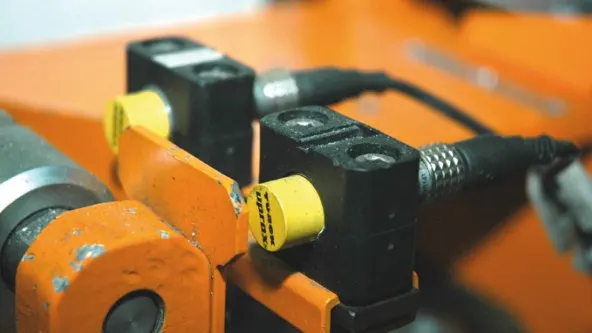
Question 16. What is a Rough locator unit & what are the basic fundamentals to consider while designing it?
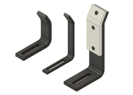
Answer 16. ROUGH LOCATOR UNIT- A Rough locator is a part designed to guide the operator, to locate the car panel on the pins accordingly.
A rough locator can be standard part or make part.
Fundamentals of a rough locator design-
- Rough locator should be placed at the edges of the car panel, which it has to guide.
- Rough locator should be placed in the same angle of the car part edge with a minimum distance of 2 – 5 mm from the edge of car part.
- Rough locators should guide the panels in pin arresting direction in general.
- Rough locators should start guiding the panel before 10 t0 15mm to the start of the pin engagement.
- Rough locators should be designed with entry angle for car part entry.
- Rough locators should be designed with two slots to mount for easy adjustment in general.
- The slots should be in the direction of car part guiding.
Question 17. What is a Base unit and describe it's parts?
Answer 17. Base unit is the unit designed to mount all the other unit like clamp unit, pin unit, rest unit, etc. of the tool, also other parts like pneumatic valve box, trunk cable path will also be mounted on to a base unit.
Parts of Base Unit-
Parts of base unit are as follows-
- Valve box
- Trunking channel
- measuring hole cover
- Eye bolt
- Pedestal
- Floor plates
- Valve box-
Valve box is basically a box which supplies air to all the pneumatic cylinders assembled in the fixture.
Valve box consist of one solenoid valve is used to collect the air from the pneumatic cylinders to valve box.
- Trunking channel-
Trunking channel is a kind of cable duct, which helps to guide and protect the wirings/tubes used in the fixtures.
- Measuring hole cover-
In the measuring hole cover the coordinates points are engraved on it.
The hole which mention the coordinates gives the position & placements of the particular units.
The measuring hole helps in CMM inspection & QC inspection.
- Eye bolt-
An eye bolt is a bolt with a loop at one end. They are used to firmly attach a securing eye to a structure, so that ropes or cables may then be tied to it for lifting purpose.
Eyebolt is used to frag or lift the base unit while relocating.
- pedestal-
Pedestal is a stand like structure where the entire unit of the base will be mounted.
- Floor plates-
Floor plates are used to mount the entire base with the floor.
Also it helps to achieve the flatness of the fixture.
Question 18. What is a Dump Unit and what are its functions?
Answer 18. DUMP UNIT-
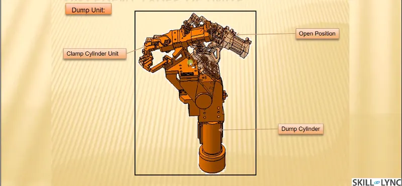
- Dump unit is used where the component to be assembled has certain constraints. Here we have clamp unit, pin unit attached panel will be assembled. If we have certain constraint we cannot assemble in normal way.
- Dump unit is used in different ways. It has dump cylinder & complex design.
- It consists of dump cylinder to perform the operation of clamping & unclamping car panel.
- It can have more than one cylinder for such operations.
- The first cylinder dumps the assembly carrying clamp Mylars,pins and then this assembly performs required operation in this unit.
- One should make sure that in the open position, it is able to remove the panel.
Functions of dump unit-
- Dumps units are used when we can not use normal units like clamp unit, pin unit unit,etc., Due to some space constraints. The designed parts should be small in size but can do their functions effectively.
Question 19. What is a Slide unit? Mention where Slide units are commonly used.
Answer 19. Slide units are positioning units, which are used to position the car part or panel, units, weld gun, robots for further operations.
Slide units may be classified into two types based on the type of guide ways. They are,
- Hardend guide way.
- LM guideway.
Slide units may further classified into three types based on the prime mover. They are,
- Manual slides.
- Hydraulic/pneumatic slides.
- CNC slides.
It may be further classified depending on the application as
- horizontal slide unit.
- Vertical slide unit.
- Angular slide unit.
Basic fundamentals of slide unit design:
Reverse stroke of 10mm to be considered in both forward & retracted condition.
Cylinder & LM guides to be validate for load & stroke.
Master guideway should be constrained and the subsidiary guideway to be free.
Mechanical hard stop to be considered for both extended & retracted condition.
Shock absorber should be used for both extended & retracted condition to reduce impact load.
Slide to be locked/clamped in the working position.
Slide to be locked with a safety pin in the retracted position during transportation.
The two end limits to be sensed externally by a proximity switch.
The design should be checked for screw accessibility, ease of assembly, machinability of parts.
The LM guide & rails are integral assemblies and should not be separated at any cost.
LM guide ways to be lubricated for long life.
Slide Unit parts-
- Slide cylinder
- Guide block
- Stopper block
- Position Locking unit
- Guide rail
- Sensor unit
Slide units are commonly used in-
Slide unit is found mostly in complex fixture, where the sliding mechanism will be involved.
This type of unit used when there is some space constraints in locating the panel.
Slide application will be easy for welding.
Slide unit can minimize the cost of robot as slide unit provided to move weld gun from one weld spot to other weld spot instead of weld robot.