Week 3:- BiW Fixture Design Methodologies Challenges
1. Design Methodology: Design methodology is nothinh but the steps followed during the concept design stages of fixture design.
Design Methodology--->
-- Purchase orser
-- Input from customer
-- Persentage completion criteria
-- Design output
2. Input from customer:
- Functional requirements
- Prefered standard components
- Car Product
- Layout
- Ergo Data
- Weld study
- Standard detailing templates
3. Input from car product:
PLP points, GD&T details, 3D files, 2D files etc.
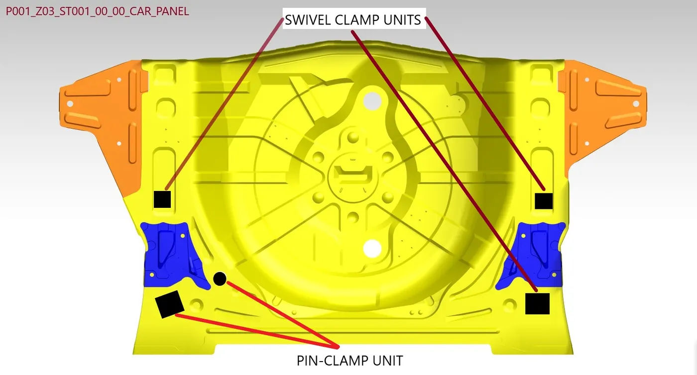
4. Clamp Plan:
Where we can place the clamping units or the pin units that input we get from the clamp plan. We should never change the input clamp data.
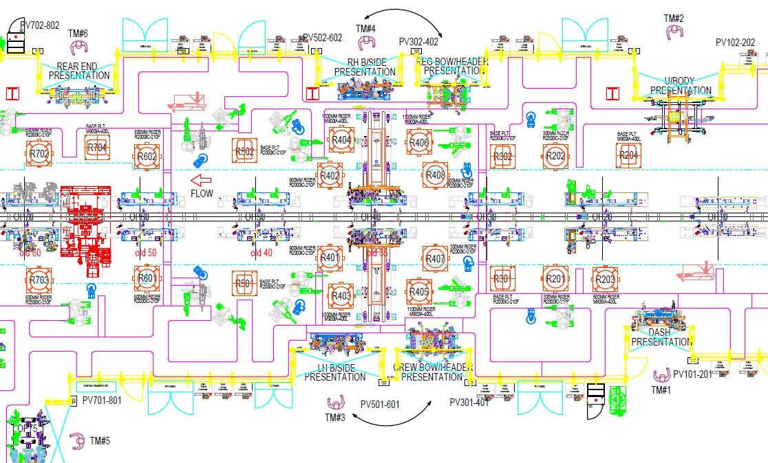
5. Layout is basically an layout of entire assembly line which helps us to understand the process, the flow of work and space constrain that we have.
6. From weld study we understand the following things--
- The gun we are going to use for welding.
- welding locations.
- Welding type
- No of welding.
- Position and cordinate of weldings etc.
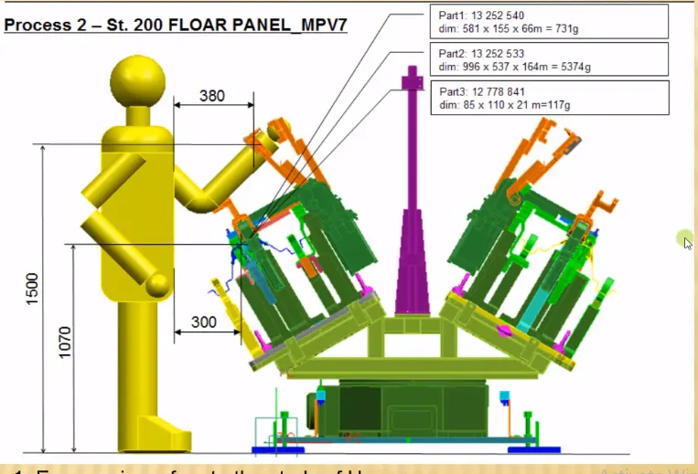
7. Ergo data:
Where we are using a manual fixture for that every company have standard ergo data and they provide it to fixture designer to design fixture considering that points. Ergo Data is used to reduce human errors, increase productivity, human comfert and safety.
8. Criteria in percentage completion in designing stage:
To complete design in time we have to create schedule or time plan called Percentage Completion Criteria. In this we mention all activities related to design and time required to complete that task like concept design, final finished design and 2D of all units in fixture etc. The persentage completion criteria is as below:
- 0-25% (Input & Concept Design): In this stage of percentage completion criteria, we have to built concept design of fixture in this stage.
- 25-40% (Concept Approval & Simulation): In this stage, concept design is approved by customer and gives some correction points if any. Later we have to to give working simulation of fixture for better understanding of how fixture works.
- 40-85% (Design Freezing & Detailing): If all requirements and specifications of customers are satisfied then design is freezed and detailing work starts.
- 85-100% (Check & Final Dispatch): In this stage, quality checking is done using CMM (coordinate measuring machine) and then dispatched to customers.
9. Design Output:
The following are the outputs--
- The output is 3D models and 2D drawings of the tools.
- Unitized tools: (multiple units on a common base) require two types of drawing sheets-
-- Key sheet: An index of units and their placements on the toolbase.
-- Layout sheet: a detailed drawing of individual units to include all of their components
- Non-unitized tools: Tools that can stand alone and can be detailed completely on a layout sheet.
10. Structuring s design tree implies to a process where all the assemblies and parts are names in a specific standards. Different customers have different ets of standards to structure a design tree.
- this helps us avoid errors during design study, manufacturing, assembly, inspection etc. If the parts or assemblies are notnamed properly or the design tree is not structured properly, it will creat confusion to understand the design & may creat major possibilities of making an error
11. Unit is nothing but a assembly having specific function like clamping, location or resting. In fixture there are number of units.
Different type of units are:
Rest unit
Fixed pin unit
Slide unit
Dump unit
Retract pin unit
12. Fixed Pin unit:
Fixed pin unit is a unit designed to locate the car panel using pins.
It restricts the rotational degree of freedom of a particular component. Also it ensures that the component is resting at the required cordinate.
13. Different parts of fixed pin unit:
Pin
Pin retainer
Shims/Spacers
Block
Blade/Adapter Plate
Riser
14. Rest unit is basicaly a unit where the component is rested. There is no upper clap to it, the re is no force to it, there is no cyliner attached to it.
Parts of a Rest unit:
Risers
Blade
Rest milers
15. Fundamentals of Sensor unit design:
- Every single loose panel which are being welded in a tool should be sensed.
- Each panel should be sensed by 1 or 2 sensors depend on the size of panel, preffered to be in diagonal opposite ends of panel.
- Every sensor should be mounted in a 3 direction adjustable way in general.
16. A Rough locator is a part designed to guide the operator, to locate the car panel on to the pins accordingly. A rough locator can be of standard part or make part.
Fundamentals of rough locator design:
- Rough locator should be placed at the edges of the edges of the car panel, which it has to guide.
- Rough locator has to be placed in the same angle of the car part edge with a minimum distance of 2-5 mm from the edge of the part.
- It should guide the panel in pin arresting direction.
- It should start guiding the panel before 10 to 15 mm to the start of the pin engagement.
- It should be designed with two slots to mount for easy adjustments.
- The slot should be in the direction of car part guiding.
17. A base unit is the unit designed to mount all the other units ( clamp unit, pin unit etc.) of the tool, also other parts necessary for a tool like pneumatic valve box, trunking cable path will be also mounted on a base unit.
Some parts of a base units are:
Trunking channel
Base plate
Valve box
Measuring hole cover
Eye bolt
Pedestal
Weld bars
Floor plate
18. Dump unit is used due to lack of space on fixture to built an unit. So, this is a complex unit consist of dump cylinder used for clamping or unclamping of car panel or component.
Function:
Due to space constrain dump unit used in fixture.
19. Slide units are basically used in palces where we can not use multiple units due to space constrains or geometrical constrains