Week 3:- BiW Fixture Design Methodologies Challenges
Week 3-Challenge 3
BiW Fixture Design Methodologies Challenges
Q1. What is Design Methodology?
Design methodology refers to the development of a system or method for a unique situation. It is a step followed during the concept designing stages. It is the study of the principles, practices and procedures of designing. The key to design methodology is finding the best solution for each design situation, whether it be in industrial design, architecture or technology. Design methodology stresses the use of brainstorming to encourage innovative ideas and collaborative thinking to work through each proposed idea and arrive at the best solution. Meeting the needs and wants of the end user is the most critical concern. Design methodology also employs basic research methods, such as analysis and testing.
It involves four major stages
- Purchase order
- Inputs from customer
- Percentage completion criteria
- Design output
Q2. What are the inputs required from the customer to start designing a Fixture?
The input required from the customer to start the work are mention below
- Functional requirements about the product/part (Welding, hemming, checking fixture position and surrounding area and storage racks).
- Preferred standard components/parts such as risers, L-block, retainers, pin, clamp, cylinder, sensors etc. From the standard company.
- Car products consists information about part list such as GD&T, product assembly process sheet etc.
- Layout consists of detailed information about plant and part in 2D.
- Ergo data provides the details about manual operator for operation.
- About weld study I.e., methods and number of weld spot/area.
- About the standard detailing templates
Q3. What is the input we get from "Car Products"?
The car product is one part of information required form the customer. It contains the information about-
- GD &T information (I.e., locating pin, rest, clamp, dumps, slide information, sequence of opening of clamp, slide stroke information)
- Part list contain the information about part thickness, material and other part details.
- Cad files of car part
- Clamp plan provide the location of pins, rest, clam, etc.
- Product assembly process sheet contain the part assembly sequence.
Q4. What is the Clamp plan?
The Clamp plan provide the information about the location of pins, rest, clamp, dump etc. A clamp is a fastening equipment it role is to hold the component firmly together, i.e. to restrict the movement of parts or sub-assemblies relative to each other. From the above definition, we conclude that clamps are most commonly used in cutting or gluing operations, welding or cutting in metalworking. There is a large number of clamps for different purposes: C-clamps, bar clamps, pipe clamps, band clamps, picture frame clamps etc. The Clamps can be found in almost every workshop, because they are simply irreplaceable.
Types of Clamp
Mechanical Actuation Clamps
Pneumatic and Hydraulic Clamps
Vacuum Clamping
Magnetic Clamping
Electrostatic Clamping
Q5. What is the purpose of a Layout?
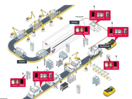
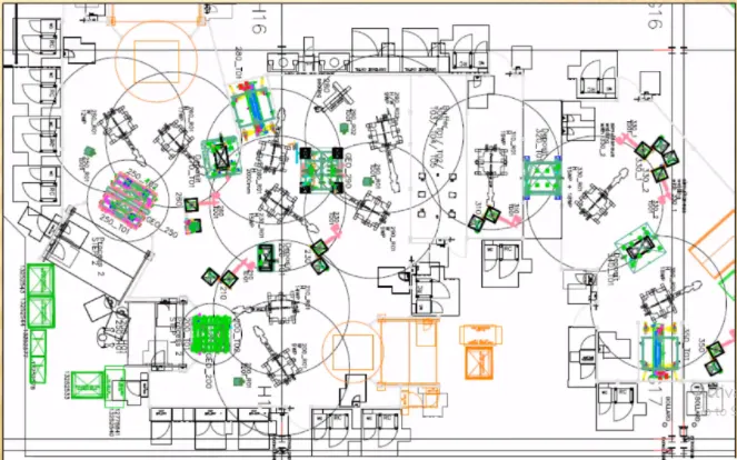
The layout provides the full information about the object/workpiece, tool/robot going to used and its functionality. Layout provides the following information-
- Flow of parts.
- Station pitch.
- Robot stations and its reachability area.
- Accessories like tool changer and tip dresser.
- Sub assembly links.
- Platform heights and human reachability.
- Loading/unloading sequence/heights.
Q6. What is Ergo data?
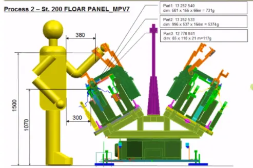
Under ergo data, the behavior of the human and movement is referred. It provides the information about human height reachability and their safety zone during the operation.
Q7. What do you understand by Weld study?
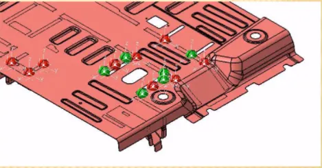
Weld study provide the information about the weld gun details, number of spots to be done and its location. The weld matrix includes geo and re-spot weld points by different color.
Q8. What are the criteria for percentage completion in the designing stage? Explain it in detail.
It is followed in the designing and dispatch stages of the welding fixtures.
The different stages are as follow as-
0-25% Input and concept design
25-40% Concept approval and simulation check
40-85% Design freezing and detailing
85-100% Check and final dispatch of the items/parts
Q9. Brief about "Design output" in design?
It is a 3D model and the 2D drawings of the tools. The tools are divided in two parts-
- Unitized tools- In this multiple units are crated on the common base. It required two types of drawing sheets.
Key sheet-consists of an index of units and their placements.
Layout sheet-A detailed drawing of individual units to includes all of their components
2. Not-utilized tools-It is tools that work alone and can be detailed completely on a layout sheet.
The design output should compile the following information
- Approved standard components are to be used wherever possible in the design.
- Design must be very simple and economical as much possible.
- Design must comply with all current safety and ergonomic (less effort) requirements.
- Desing must be fully controlled and easy work flow with free handling of product.
- The weight of the moving must be kept to minimum and same time strength must be sufficient.
- Design clearance and accessibility must be provided for the routine maintenance and service.
- For moving equipment, motion control must be considered.
- Designer is responsible to validate clamps and all weld guns.
Q10. What do you understand by structuring a design tree? How does it reduce errors during the design process?
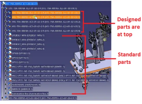
The design structure tree must be defined properly to avoid any mistakes in the design. It is a process where all the assemblies/parts are named in a specific standard. Different customer has their own different set of standards to provide the design tree. It is an important process in designing to identify a specific part/assembly to a certain project.
A proper design tree avoids the mistake/error during the process, manufacturing, assembly and inspection process by providing the specific name to each part based on the project/stage etc. Naming of fixture/unit/part, provides the proper information about to its project, zone, or assemblies.
Q11. What are Units? Mention 5 types of units.
- Fixed pin unit
- Retractable pin unit
- Rest unit
- Clamp unit
- Sensor unit
Q12. Describe Fixed Pin units & their purpose?
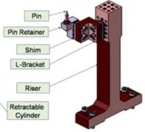
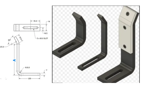
Fixed pin unit is designed to locate the car panel using pins. It consists of different part such as pin, pin retainer, shims/spacers, block, blade or adaptor plate and riser as peesented in the below figure.
Q13. What are the different parts of a fixed pin unit?
Under this pin have two shapes i.e., round & diamonds depend upon the 2 ways and 4ways location.
Q14. What is the purpose of making a Rest unit & describe its parts?
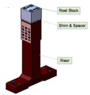
It is used to rest the components/part on it during the operation. The shim and spacer are used to adjust rest block as per requirement. The riser is used to get the part at the required heights and generally it is used as standard part.
Q15. What are the basic fundamentals to design a Sensor unit?
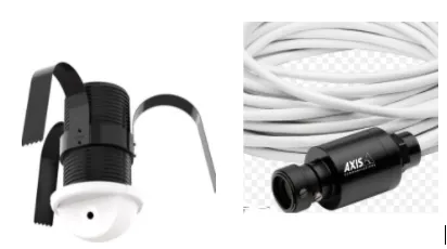
This unit is designed to sense the position/weight of part/components. Once, one process is completed and signal will be sent then only second operation will start. This will avoid any accident during the operation. Different types of sensors such as proximity sensors, laser sensors, photo electric sensor etc. used in automobile industries. Every single loose panel are joining together should be sensed. For big panel, the sensors must be mounted diagonally for better response and it should be 3 directions adjustable.
Q16. What is a rough locator unit & what are the basic fundamentals to consider while designing it?
It is part designed to guide the operator to locate the car panel on to the pins as per the requirement. A rough locator can be of standard part or make part.
Point must be considered
It is placed at the edge of the car panel, which it has to guide.
It must be placed in the same angle with the car part edge with a minimum distance of 2-5 mm from the edge of the car part.
It should start guiding the panel before 10-15 mm to the start of the pin engagement.
It is designed with entry angle for car part entry.
The slots should be in the direction of car part guiding.
Q17. What is a Base unit and describe its parts?
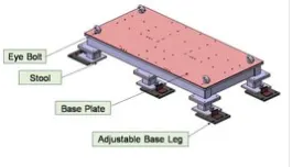
Base unit is used to mount all the units on it for any operation. Under it eyes bolt is used to lift or carry base, and stool used to provide the required height. Base plate is used to mount unis/parts. Its height must be designed as per the operation whether manual or robotic. For the manual working condition height should be in range of 850 mm to 1100 mm. It designs should deflection less and vibration free.
Q18. What is a Dump Unit and what are its functions?
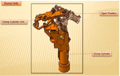
Dump unit is a complex unit which has a lot of parts. Hence, we need to be extra cautious while designing a dump unit because any mistake in design can result in irreversible errors that can create wastage of time and money.
It is used for complex region where simple unit cannot be fixed. The weight of the dump unit must be less as much as possible, it helps to reduces the forced required. It can have more than one cylinder to perform the complex operation. In this unit make sure that in open condition of the panel, one should be able to remove the panel.
Q19. What is a Slide unit? Mention where Slide units are commonly used.
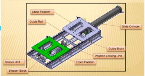
This units consists of clamp, rest unit or pin. It is used to move the component forward and backward as well up and down direction to perform the work. After completion of work, it can be easily removed from the working space. The cylinder is used to provides the required motion. The sensor unit is also provided in the last of the slide to avoid any accident and to check the proper fixing of the parts. It is used at place where are space limitation and place where less accessibility. The pull and push action should be less as much as possible. It is majorly considered when slide unit is in inclination.
*****************************************************************************************End of Report*************************************************************************************