Meshing of Automotive Hoods within certain Element Criteria Using ANSA
Meshing of Automotive Hoods within certain Element Criteria Using ANSA:
Abstract:
This project deals with the meshing of the automotive sheet metal component using ANSA. The sheet metal components are used in the automotive for the automotive body sections and also automotive closures such as doors, hoods etc. Since the sheet metal components are thin walled components, where the thickness of the component is very less when compared to that of other two dimensions. So the shell elements are mostly used for modelling the sheet metal components, thereby converting the complex 3D geometry into 2D geometry for the simulation. For meshing the components using shell elements, the mid-surface of the component has to be extracted. That mid-surface has to be meshed and the thickness has to be specified as property to indicate the third dimension of the component. The main objectives of this project are
- Check for geometrical defect on the given model
- Extract the mid surface
- Assign the property ID to the mid surface
- Assign the element quality criteria
- Perform the mesh
- Clean up any OFF elements present in the system.
The quality criteria required for the elements are indicated in the following table.
|
Target / average length |
5 mm |
|
Minimum length |
2 mm |
|
Maximum length |
7 mm |
|
Aspect ratio |
3 |
|
Warpage |
15o |
|
Skewness |
45o |
|
Jacobian |
0.7 |
|
Minimum Quad angle |
45o |
|
Maximum Quad angle |
135o |
|
Minimum Tria angle |
30o |
|
Maximum Tria angle |
120o |
|
Tria percentage |
15 % |
Other important quality criterion to be met are:
- Mesh has to be good, to transport the energy across the components in a uniform manner.
- There should not be tria elements at the perimeters of the surface
- In general limit the usage of tria elements.
Introduction:
The automotive hoods are one of the automotive closures used in the vehicle to cover the engine, radiator, battery and other components at the front in a traditional front mounted IC vehicle. In modern electric vehicle the automotive hood is used to cover the luggage area, since there is no need of heavy engine in it. The automotive hood will be hinged at one end and can be opened using other end. There will be latch assembly to fix the front end of the hood in an open position. The automotive hood plays a major role in aerodynamic and NVH behavior of the vehicle. In addition it plays a crucial role in the pedestrian safety.
The automotive hood consists of mainly the inner and outer surfaces. These two surfaces are stamped separately and will be joined together by the hemming process. Hemming is a sheet metal forming process where the edge of the sheet is bent to 180o by plastically deforming the sheet to bend up on itself or over other sheet. Hemming is used to joining two sheets together by bending the edge of the outer sheet over the inner sheet. It is also used to create a smooth edge by bending the edge of the sheet onto itself to avoid sharp edges and improves the aesthetics of the sheet. The adhesives can be used to increase the strength of the hem. Before finalizing the design of the automotive hood, this hemming process will be simulated, to check for any cracks in the bent region, stress, strain and deformation in that region and also the roll-in and roll-out values. These are important because during the hemming process, the dimension of the sheet will change. So, the designer has to take the effect of that also before designing that. This stress, strain values are also important for the performance of the hood, since the hood will be loaded at region during opening and closing of hood. Therefore it will experience creep over long period time. And hemming is also a joining which will have some impact on the crash simulation. So simulation of the hemming process is important for hoods and doors.
The automotive hood is a sheet metal component, where the thickness of the sheet is less than other two dimension. So the shell elements are used on the mid-surface of the components of the automotive hood to model the automotive hood. All the components of the automotive hoods has to be modelled using FE-elements for the further simulation. The type of shell element is based on the type of the simulation and the thickness of the sheet.
Model:
The hood is divided into
- Outer hood sheet
- Inner hood sheet
- Hinge reinforcement area
- Latch reinforcement area
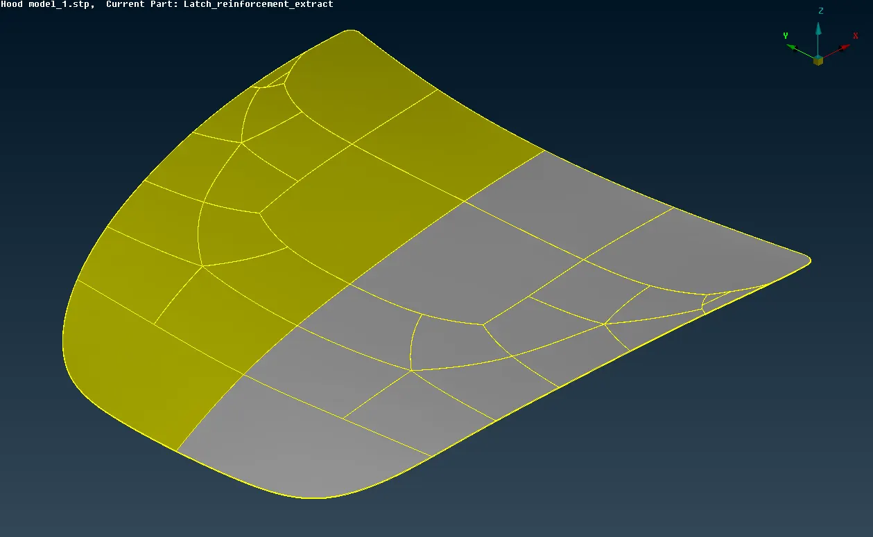
Fig 1.1: Outer hood sheet
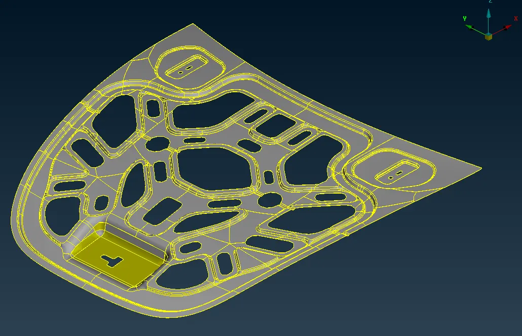
Fig 1.2: Inner hood sheet
The automotive hood has a no features on the outer sheet and has lot of features on the bottom sheet.
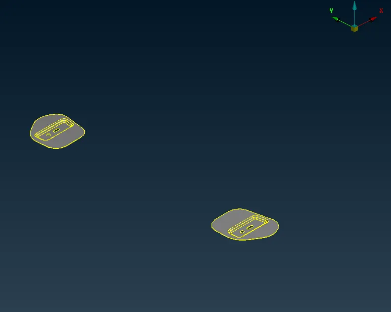
Fig 1.3: Hinge Reinforcement
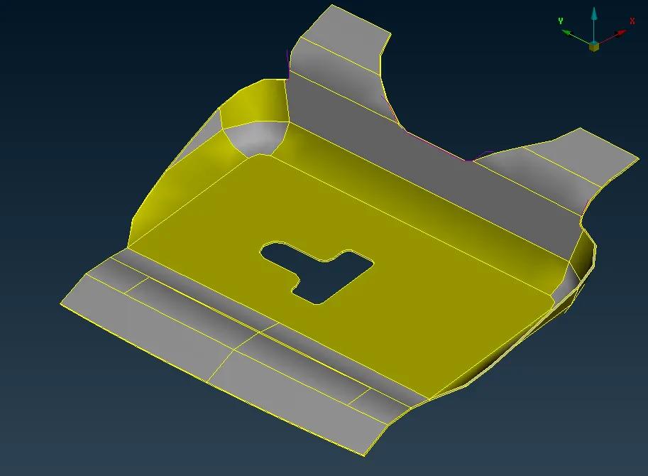
Fig 1.4: Latch Reinforcement
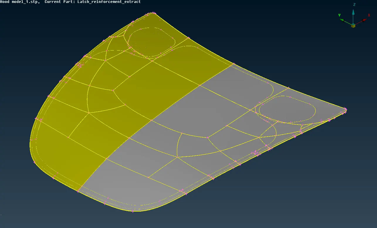
Fig 1.5: Assembly - Isometric view
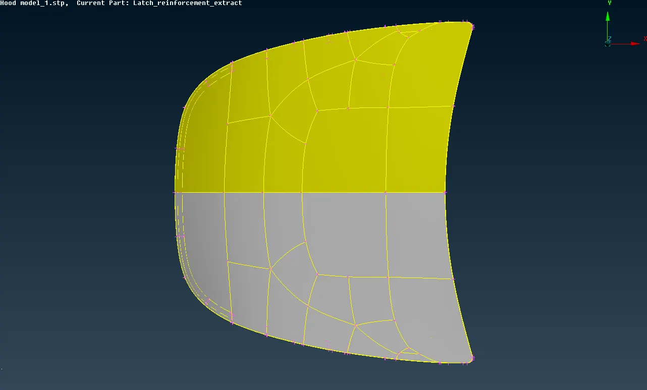
Fig 1.6: Assembly - Top View
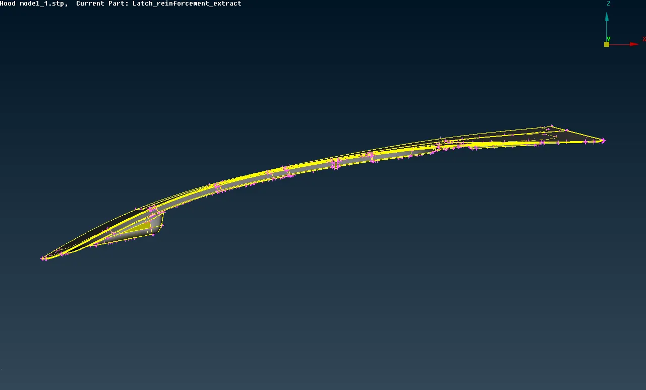
Fig 1.7: Assembly - Side View
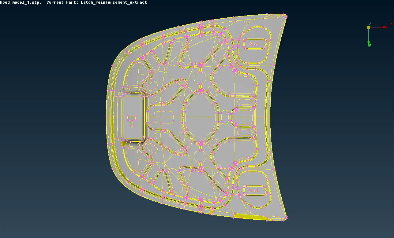
Fig 1.8: Assembly - Bottom View
Geometry clean-up:
The geometry imported into the ANSA is first prepared before proceeding with the FE-modelling. The geometry orientation is aligned and will be cleaned of any defects in the geometry.
The orientation of the component has to be aligned. The orientation of the model can be found in ANSA in the “entities” draw mode.

Fig 1.9: Entities draw mode
The orientation is represented in the grey and yellow colour, with grey being positive and yellow being negative.
Fig 1.10: Orientation of the outer sheet
Fig 1.11: Latch Reinforcement
From the figure 1.10 and 1.11 it can be seen that the outer sheet and the latch reinforcement has both the orientations on a single side. An entire side of the component must be aligned to a single orientation. This orientation determines the orientation of the mid-surface, which in turn determines the orientation of the shell elements. All the shell elements has to be orientated along the single direction, because the element normal will be along that direction. This element normal determines whether the component undergoes tension or compression and direction along which the stress and strain tensors are directed at.
The orientation of the surfaces are aligned using Topo → Faces → Orient.
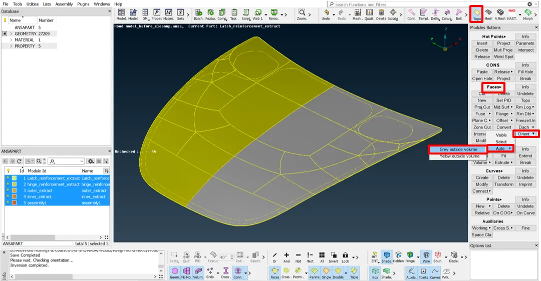
Fig 1.12: Changing the orientation
Auto orientation option is used and the grey orientation is chosen for the outside volume. Thereby ANSA will automatically convert all the yellow orientation of the outside volume to grey.
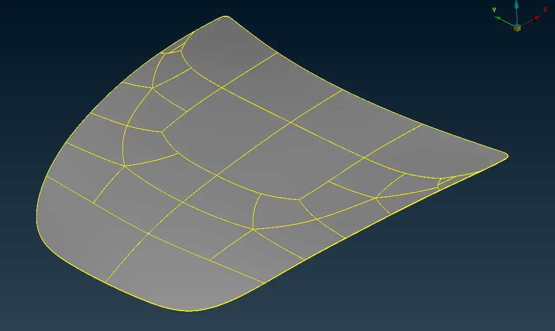
Fig 1.13: Outer sheet after changing orientation
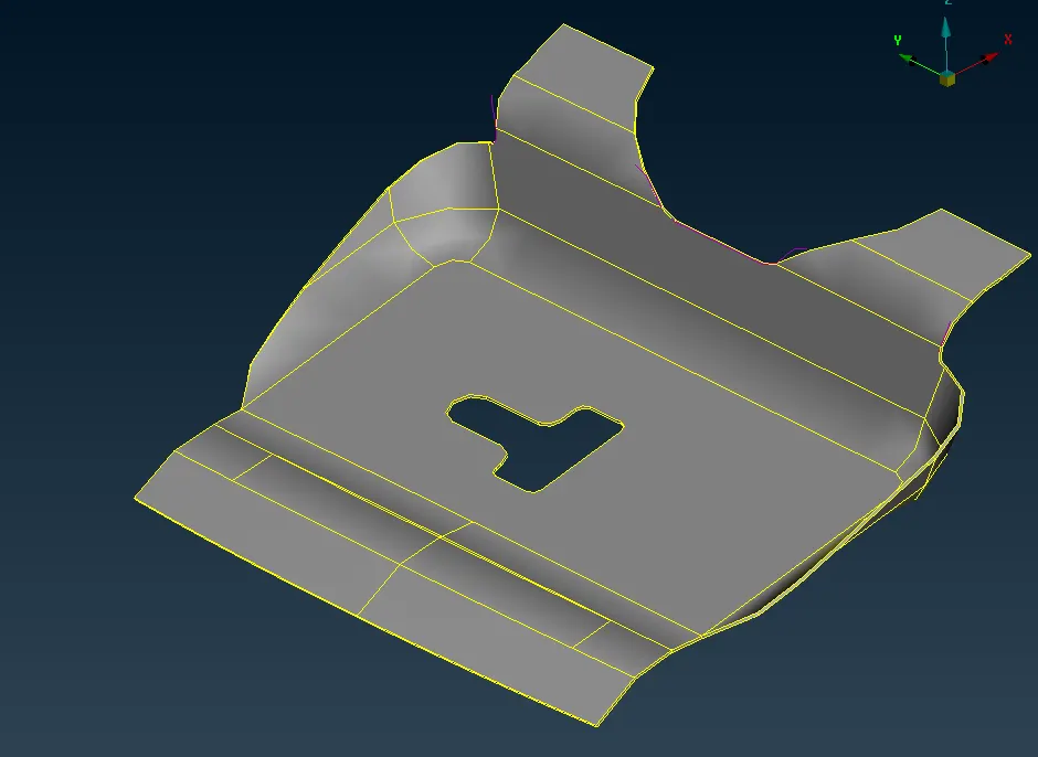
Fig 1.14: Latch reinforcement after changing orientation
Then the geometry is checked for any errors such as presence of crack, single cons, triple cons, overlap faces etc. The geometry is checked using the Tools → Check → Geometry.
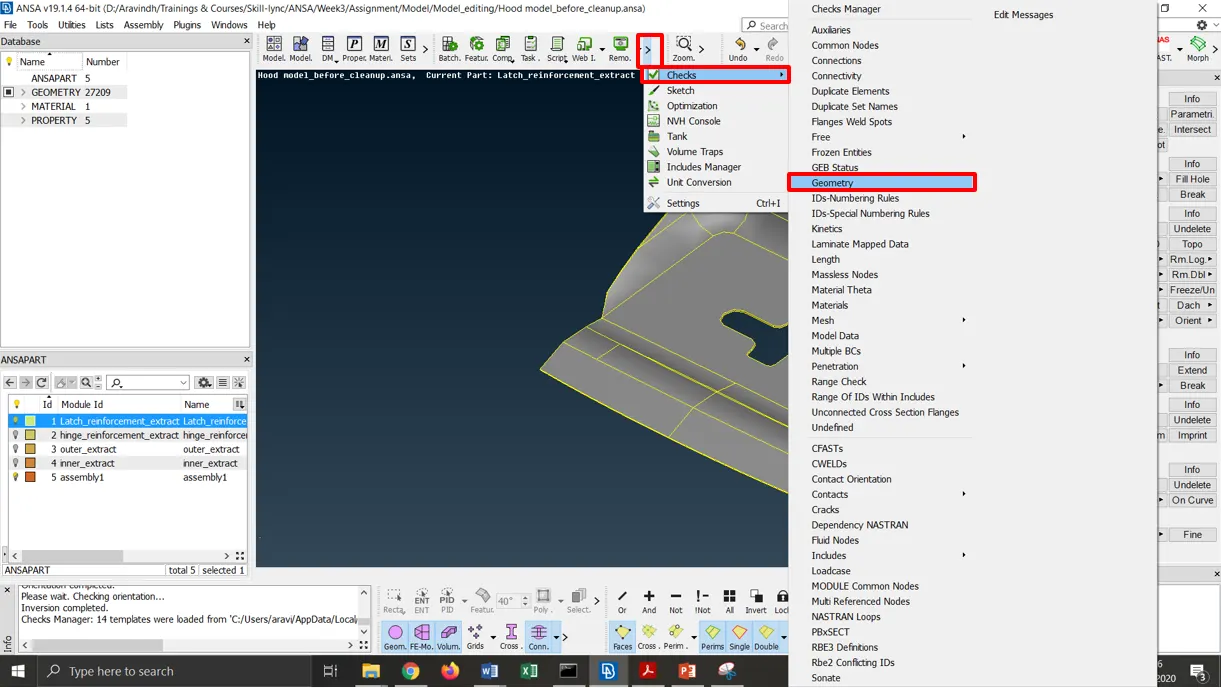
Fig 1.15: Check geometry option
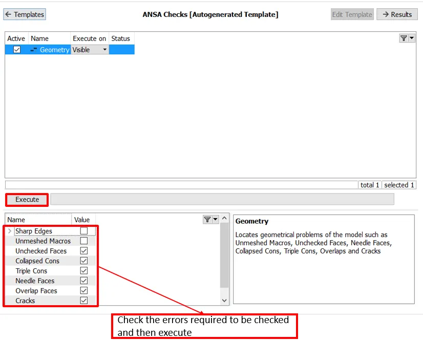
Fig 1.16: Check geometry parameters
In the check geometry dialog box, the errors that are needed to be checked in the model are checked and it is executed. ANSA checks the whole model for these errors or deviations and throw up the errors at the end. These errors could have been in the model due to errors committed during the design stage or due to importing the CAD model into the pre-processor. When the model is imported from the CAD software like CATIA or SOLIDWORKS etc. to the pre-processor like ANSA or HyperMesh etc., there could be some compatible issues, thereby resulting in small translational errors. Either way these errors has to be fixed before proceeding to the meshing. Since the mid-surface with cracks can result in FE-Models with cracks, which while simulating gives false material failures. So these has to be cleaned before meshing.
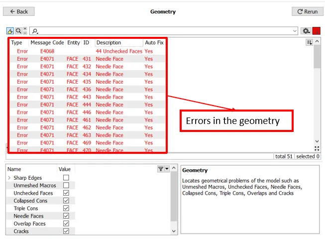
Fig 1.17: Errors in the geometry
There are 44 unchecked errors. This has to be rectified. It can be performed manually or automatically. ANSA can rectify few small errors by itself. This saves time. The errors can be rectified automatically using Select all the errors → Right click → Fix.
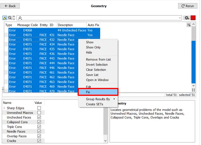
Fig 1.18: Fixing the errors in the geometry
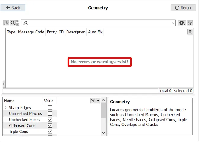
Fig 1.19: After fixing the errors in the geometry
Thereby ANSA has automatically fixed the errors. After rectifying the errors, ANSA reruns the check and gives the result.
Checking the Property and Material ID:
The property ID and the material ID for each component is checked and checked whether the material is assigned for each property and whether that material is “defined” in the material card.
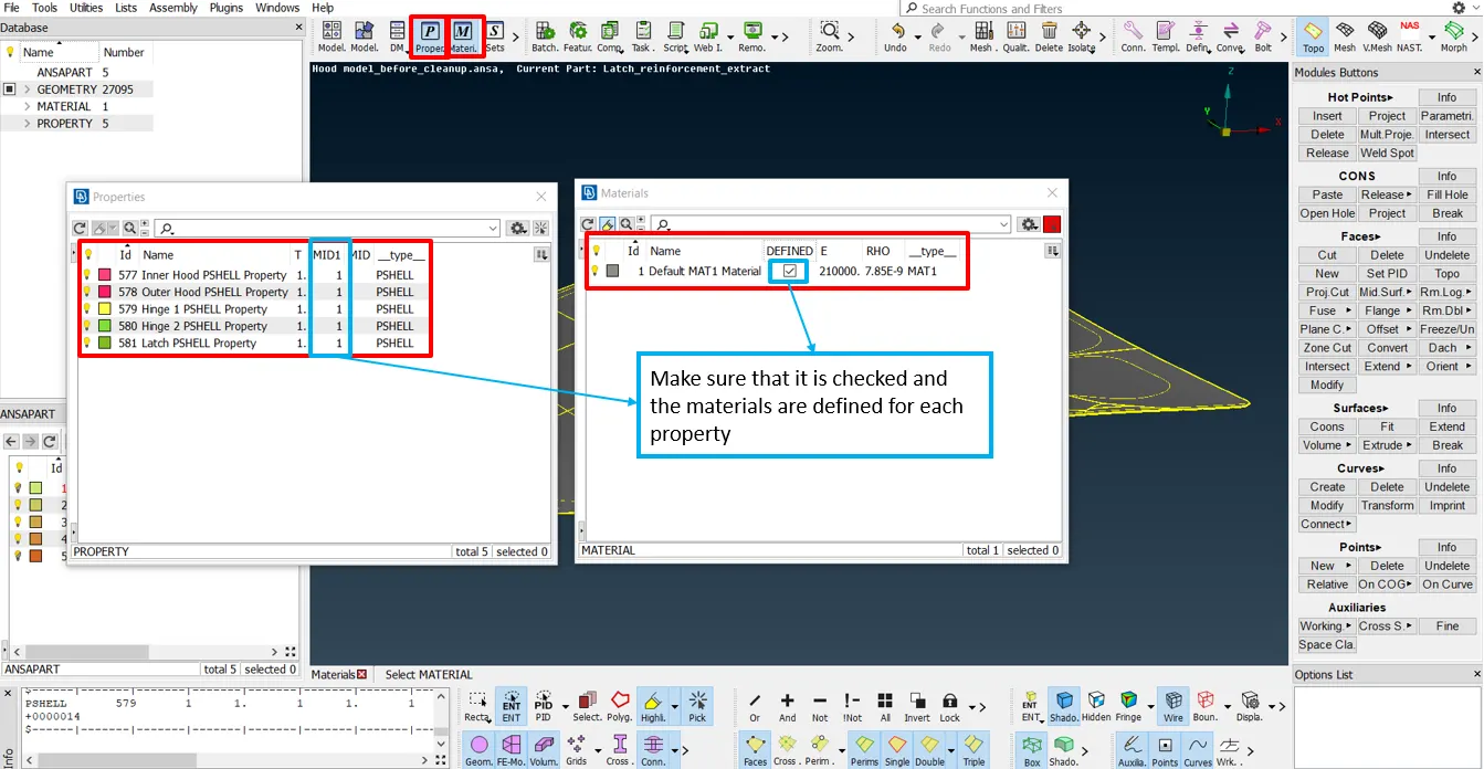
Fig 1.20: Property and material ID
Extracting Mid-Surface:
After the geometry clean-up, the mid-surface of the components are extracted. Since these are sheet metal components with small thickness, shell elements are used for the simulation, thereby converting the 3D problem into 2D problem and solving the problem at much faster than the solid elements due to the number of total nodes in the components.
For extracting the mid-surface, the thickness of the components has to be checked, to know the thickness of the component and to check whether it is uniform throughout the model. For measurement in ANSA measure tool is used. The measure tool can be accessed by Utilities → Measure
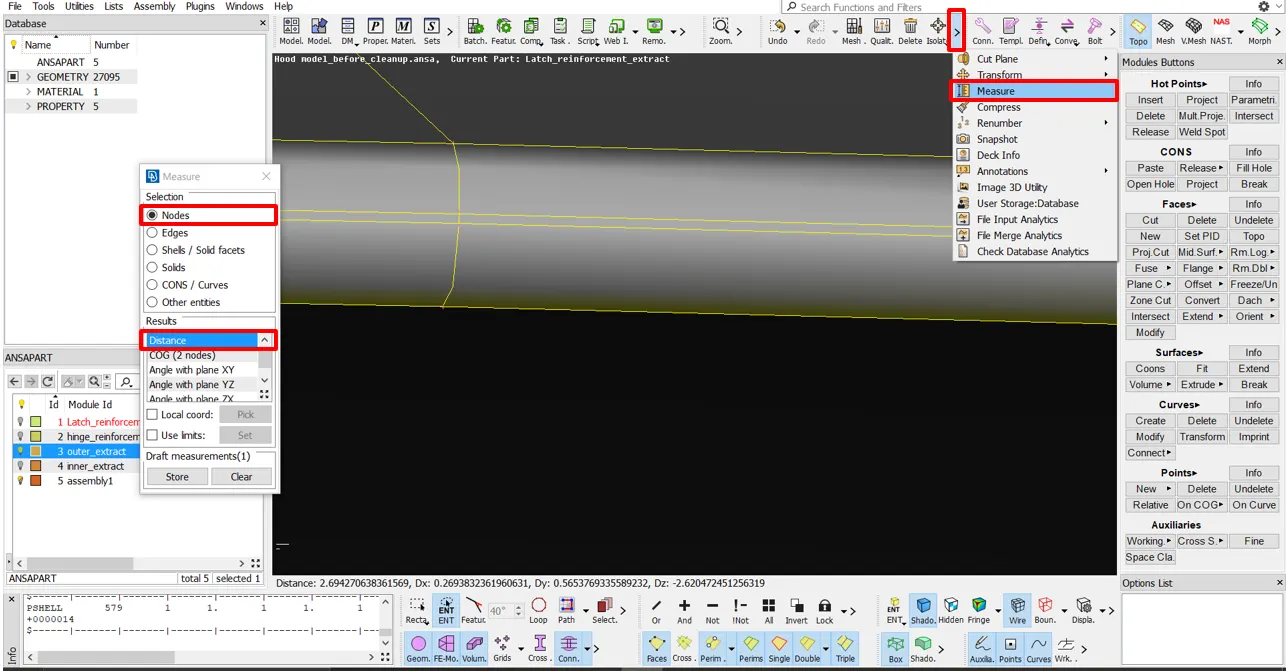
Fig 1.21: Measure tool in ANSA
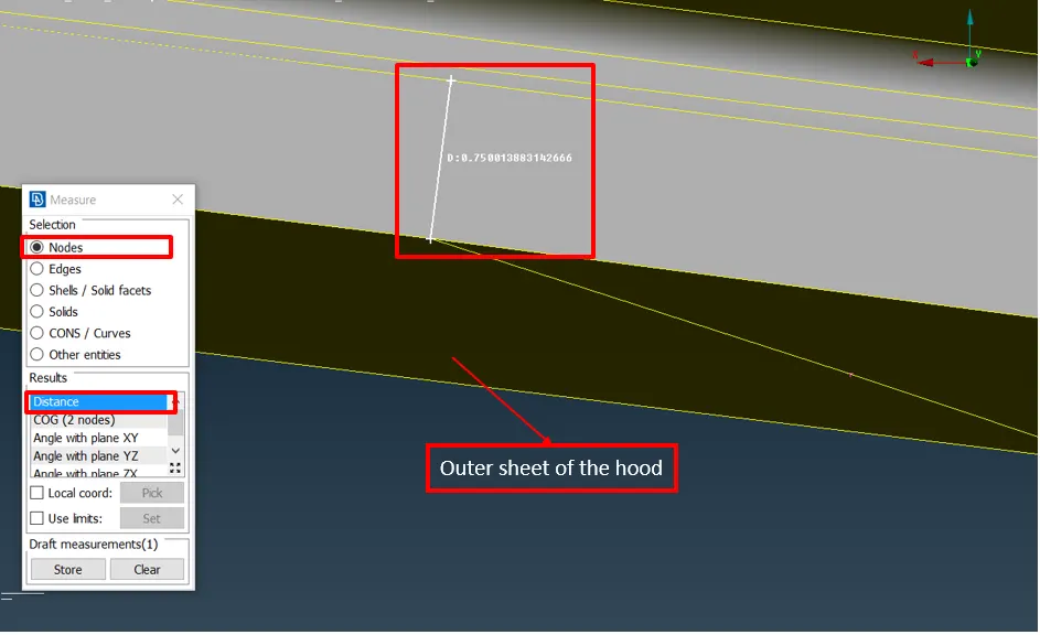
Fig 1.22: Measurement of the outer sheet of the hood
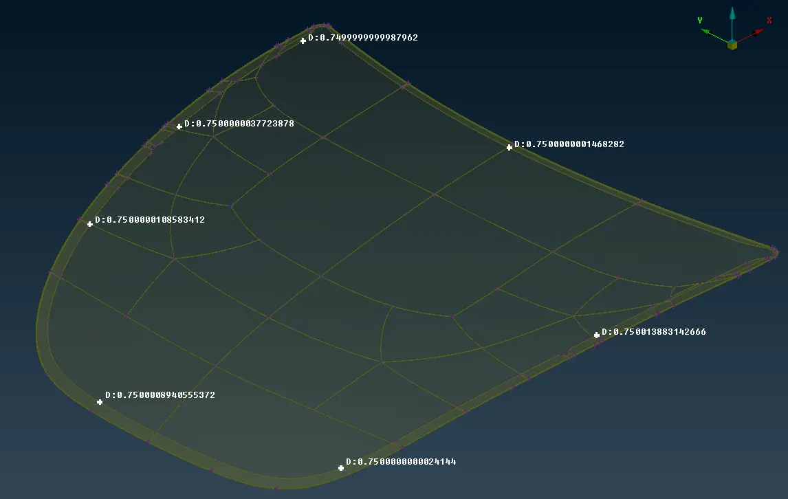
Fig 1.23: Measurement of the outer sheet of the hood taken at multiple places
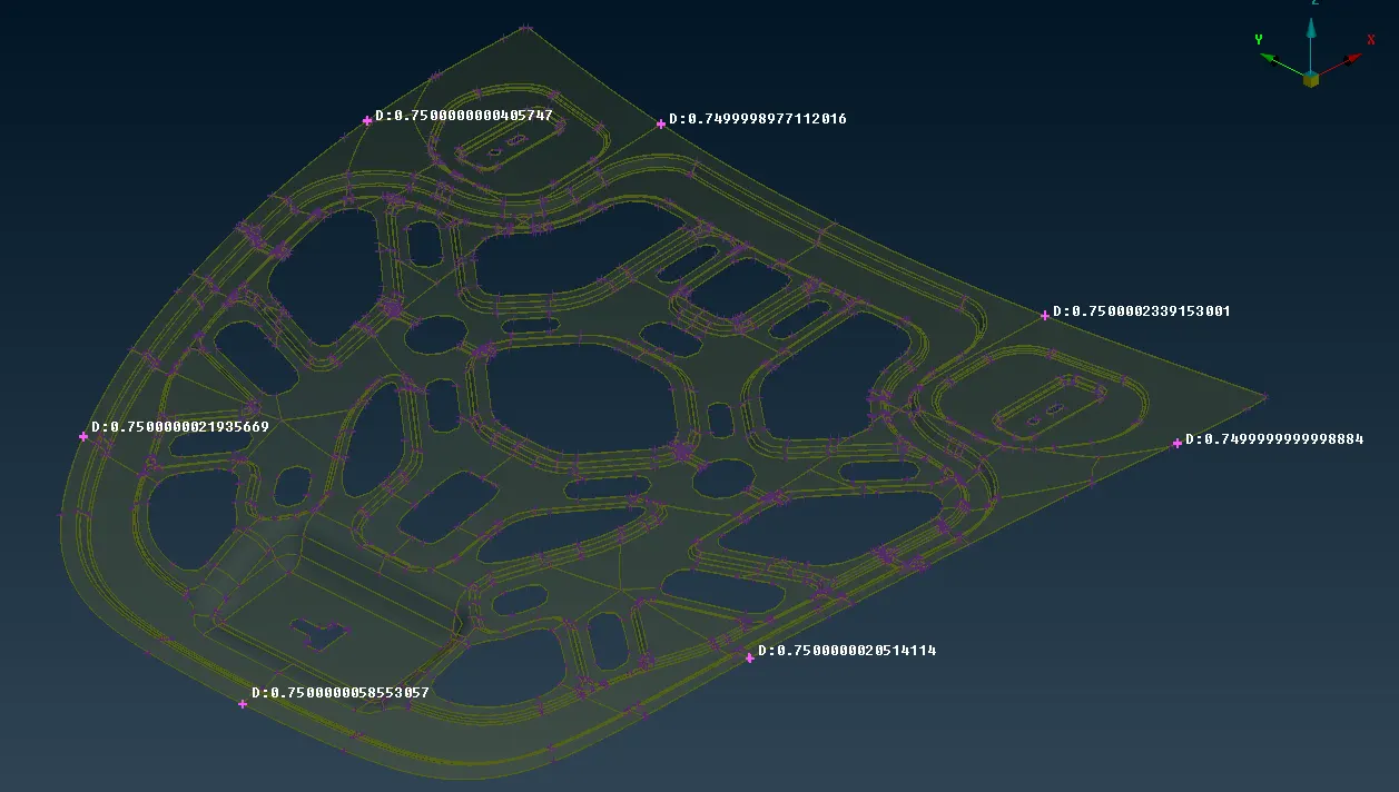
Fig 1.24: Measurement of the inner sheet of the hood taken at multiple places
After the measurement of the inner and the outer sheets of the hood, it has been determined than the thickness of both the sheets are 0.75 mm. The thockness of the hinge and latch reinforecemnts are 1.2 mm.
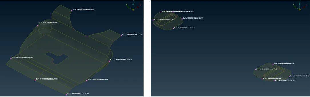
Fig 1.25: Measurement of the latch and Hinge of the hood taken at multiple places
Using these thickness values, the mid-surface of the components can be extracted. The mid-surface is extracted using the “offset” option which can be accessed using Topo → Faces → Offset → Faces.
A surface is selected for the offset. ANSA will show the direction of the offset. Considering that direction the value of half the thickness is given as the offset value. Using “offset” option will retain the parent surface, which can be used in future if there are many modifications necessary.
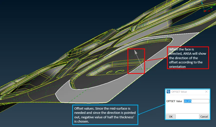
Fig 1.26: Offset parameters for the inner sheet
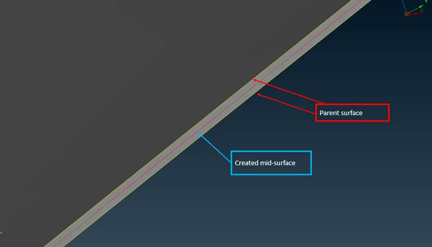
Fig 1.27: Mid-surface created by the offset
By this method, the mid-surface can be extracted. All the faces of the component can also be selected together and offset together.
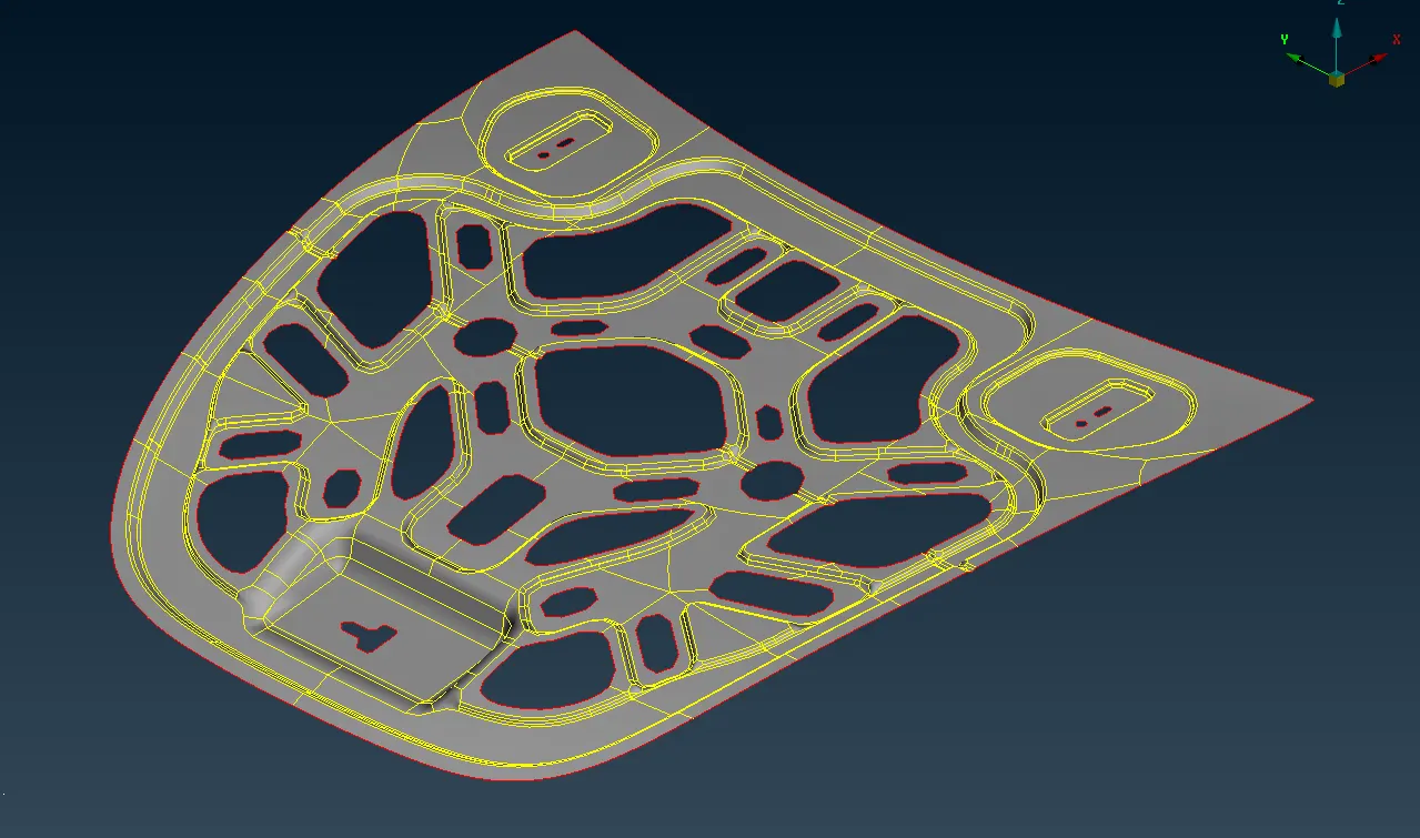
Fig 1.28: Mid-surface of the inner sheet of the hood
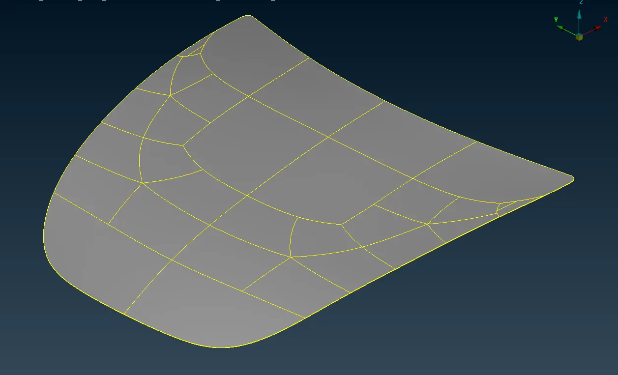
Fig 1.29: Mid-surface of the outer sheet of the hood
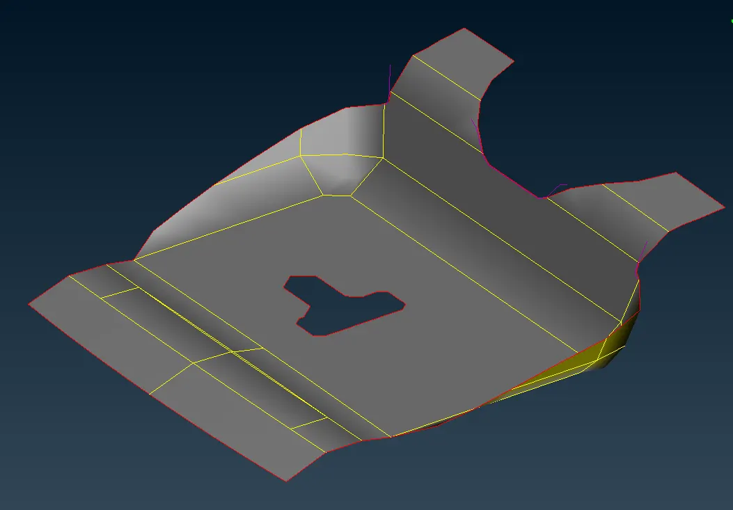
Fig 1.30: Mid-surface of the latch of the hood
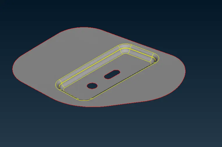
Fig 1.31: Mid-surface of the hinge of the hood
Creating the Property and Assigning Material ID:
The property ID is created for each and every mid-surface and the material is assigned to it. In the property card, thickness of that particular component is included in the column given for the thickness.
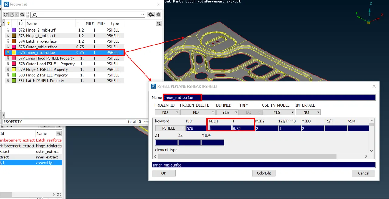
Fig 1.32: Property of the mid surface and the material ID assigned to it
Creating the Geometry of the Mid-surface:
Then the mid-surface geometry is checked for any errors such as presence of crack, triple cons, overlap faces etc. The geometry is checked using the Tools → Check → Geometry.
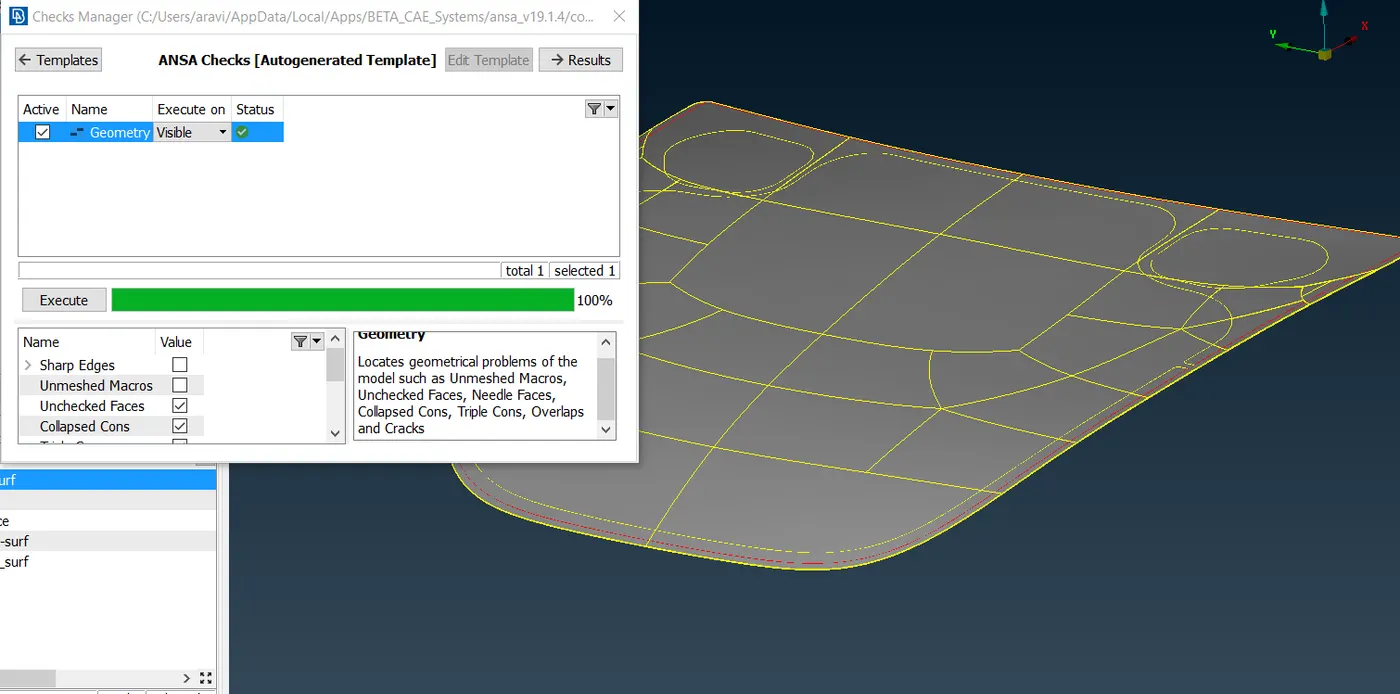
Fig 1.33: Geometry check of the mid-surface
Preparing the Geometry of the Mid-surface for Meshing:
The created mid-surface consists of many small features which when meshed will give very small elements, and which when used for the simulation will lead to small time step size, thereby increasing the total simulation time.
Therefore these features has to be de-features such that there are no material removal or geometry change in the model.
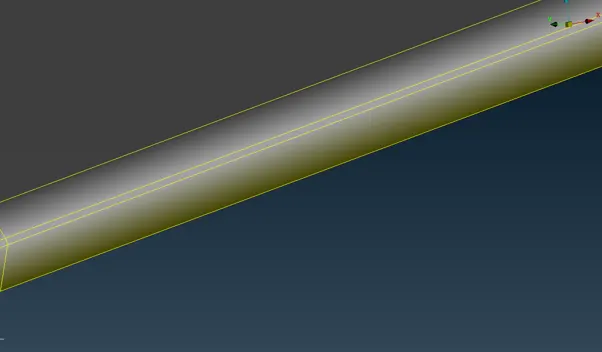
Fig 1.34: Outer sheet before geometry preparation
The outer surface has the fillet at the side, which represent the hemmed section. The size of the fillet is very small. Therefore, these fillets are joined with the adjacent surfaces using the “Cut” and the “DACH” options, so that these small surfaces can be neglected without the material removal.
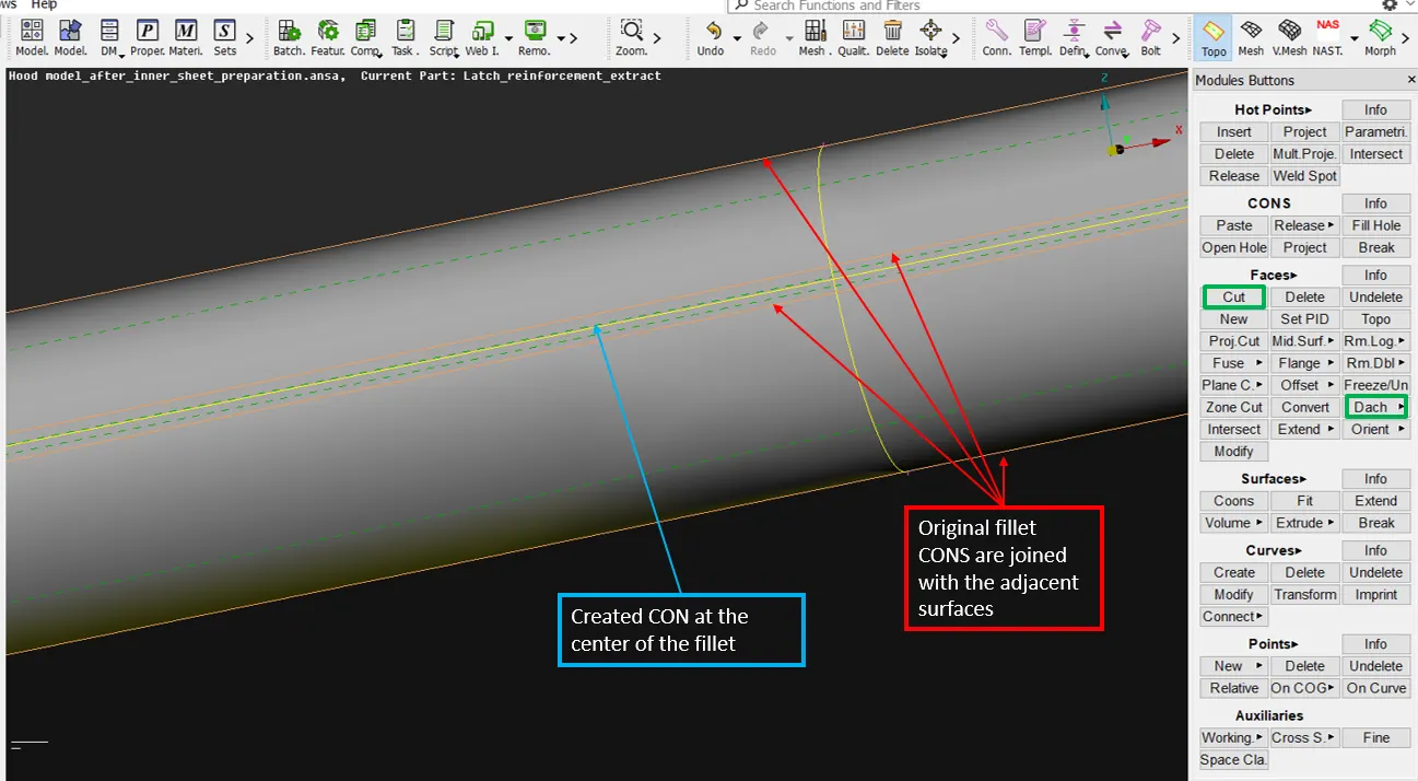
Fig 1.35: Outer sheet after geometry preparation
The inner sheet of the hood has the many features which are very small, and the surface is also very complex. Therefore, that sheet is cleaned using the same options.
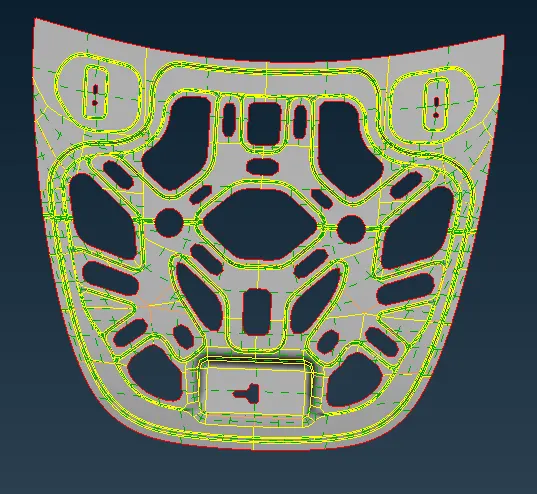
Fig 1.36: Inner sheet after geometry preparation
Meshing Parameters and Quality Criteria:
The perimeter is divided into many nodes depending on the required element size. The perimeter is divided using Mesh → Perimeters → Length.
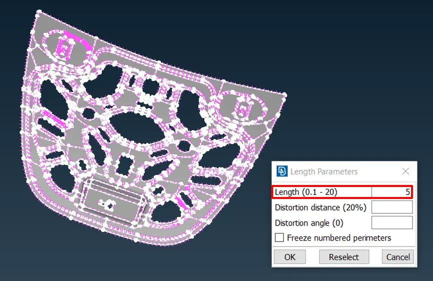
Fig 1.37: Perimeter length for mehing
The holes in the sheet are aligned using Mesh → Perimeters → Slide and Mesh → Hot points → Mark/Un, such that the edge of the holes are parallel to the nearby CON and there are even number of edges on the CON. This is done to get the good mesh flow, avoid the tria mesh and also to capture the holes accurately. Holes are important features in the geometry, as these holes experience high stress concentration under load. Therefore the holes has to be captured accurately.
Quality Criteria:
The required quality criteria of the mesh are as follows.
|
Target / average length |
5 mm |
|
Minimum length |
2 mm |
|
Maximum length |
7 mm |
|
Aspect ratio |
3 |
|
Warpage |
15o |
|
Skewness |
45o |
|
Jacobian |
0.7 |
|
Minimum Quad angle |
45o |
|
Maximum Quad angle |
135o |
|
Minimum Tria angle |
30o |
|
Maximum Tria angle |
120o |
|
Tria percentage |
15 % |
The required quality criteria are specified in ANSA using Utilities → Quality Criteria
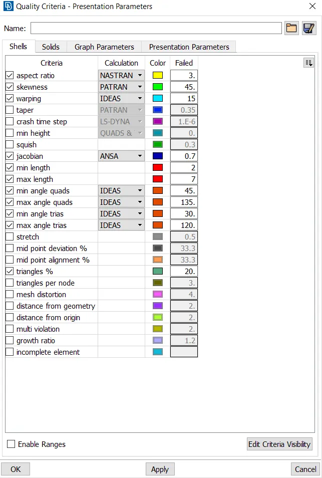
Fig 1.38: Quality Criteria
The mesh parameters such as type of mesh, elements are specified using Utilities → Mesh Parameters
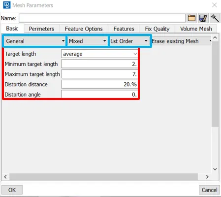
Fig 1.39: Mesh Parameters
Meshing:
Meshing of the component is the most important step in numerical simulation. The result of the simulation is highly dependent on the mesh quality and mesh flow. Coarse mesh can lead to result which is much more deviated from the actual result. The fine mesh can lead to good result, but the simulation time will be high. The optimal mesh should consider both the accuracy of the result and the simulation time. The mesh has to be as uniform as possible, since the non-uniformity among the mesh can lead to inaccurate result. The ideal mesh contains no trai elements. Since the tria element are stiffer than quad element and also has high stress concentration along the corners. So the number of tria elements has to as minimal as possible.
The sheets of the hoods are meshed using Mesh → Mesh Generation → Best
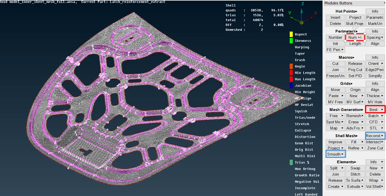
Fig 1.40: Mesh Options
The created mesh is refined using Mesh → Shell Mesh → Reconst. / Smooth or using Mesh → Perimeters → Num+/- options to create a good mesh flow, reduce the tria elements and to remove any quality defects. Using “Reconstruction” option, the created mesh is again constructed in an optimal method in the selected region. The “smooth” option is used to smooth the mesh at the selected region to improve the mesh flow. “Num+/-” option is used to adjust the number of nodes at the corner to get the quad element instead of tria.
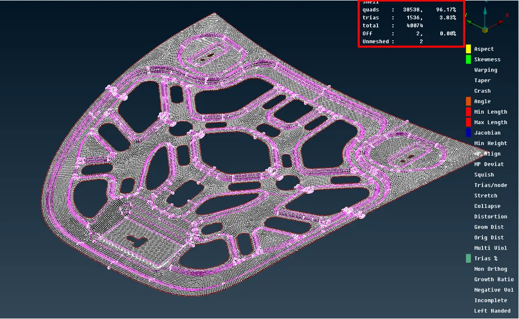
Fig 1.41: Inner sheet mesh
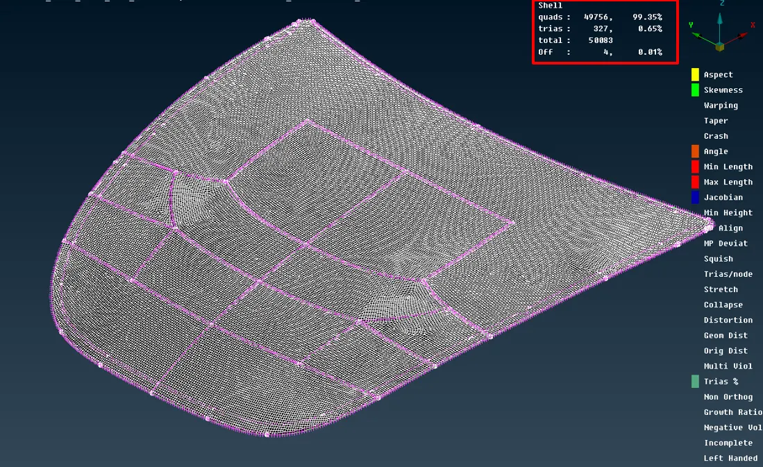
Fig 1.42: Outer sheet mesh
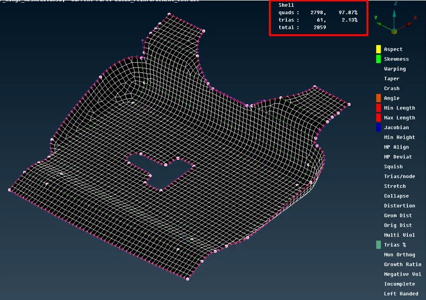
Fig 1.43: Latch mesh
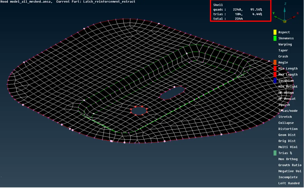
Fig 1.44: Hinge mesh
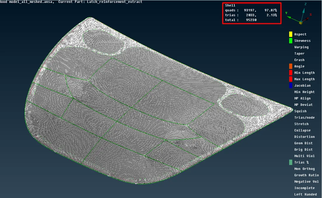
Fig 1.45: Automotive hood mesh
All the components of the automotive hood is meshed within the required quality criteria.
There are total of 95,230 elements of which there are 93.197 quad elements and 2033 tria elements. The percentage of tria element in the model is around 2.13%. The percentage of the tria element is very less than the maximum allowed tria percentage. There are no OFF elements and unmeshed component in the system. Therefore, the mesh is of good quality.
Learning Outcomes:
The procedure for cleaning the sheet metal component, extracting mid-surface, definitions quality criteria of mesh and creating the 2D mesh for the sheet metal components within the given quality criteria for FE analysis are learnt through this project. In addition to the procedure, knowledge of various tools and shortcuts in ANSA are acquired.
Conclusion:
The automotive hood is considered for pre-processing using ANSA: The geometry of the hood is oriented along one direction and the property and the material is assigned to the components of the hood. The geometry of the components are checked for errors in it such as triple CON, cracks etc. and are cleaned from every errors in it using “Check Geometry” option. Then the mid-surface is extracted manually using “offset” option. The extracted mid-surface is cleaned of geometrical defects and assigned the new property for it, which has the thickness of the component, which now is an important property, since this thickness will be associated with the shell elements during simulation. The material is assignd to the properties of the component. Then the components of the hood are meshed using the 2D shell elements using “Best” meshing algorithm. The created mesh is refined to clear off any quality failures, to reduce triangular elements and to improve the mesh flow using “Reconstrction”, “Smooth” and “Num+/-” options. The final created FE-model is void of any quality failures and the number of triangular elements are also around 2% of the total number of elements.