2D Shell Meshing of the Sheet Metal Components using HyperMesh
2D Shell Meshing of the Sheet Metal Components using HyperMesh:
Objective:
The objective of this assignment is to preprocess the components for the further simulation. For preprocessing the component, the component is discretized using 2D shell elements. The tasks included in the preprocessing as the part of the assignments are as follows:
- Perform the geometry clean-up operation to get rid-off any free edges or unclosed edges or edges which connects more than two surfaces.
- Extract the mid-surface of the component.
- Perform the cleaning-up of the extracted mid-surface, which involves removing certain small features which may not have influence on the simulation.
- Close all the holes with the diameter less than 5 mm.
- Mesh the components using 2D shell elements within certain quality criteria. The criteria are as follows
- Target element length – 5mm
- Minimum element length – 3 mm
- Maximum element length – 7 mm
- Avoid any quality failures such as jacobian, Warpage etc.
- Create the property for this mid-surface.
This assignment involves preprocessing of three components. Each process and results of each components will be discussed in detail.
Part 1 - Practice:
Geometry clean-up:
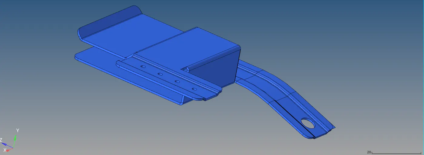
Fig 1.1: Initial
The edges of the components has to be closed perfectly to form the topology. The meshing can be performed only on the closed components. Else there will be connectivity issues. The free edges can be formed during the CAD modelling or during the import of CAD model into the HyperMesh. Importing of certain file types, can cause this errors. Whatever may the reason for these free edges, it has to be corrected before the mid-surface extraction.
The color coding can be activated by changing the options in the “Geometry color mode”

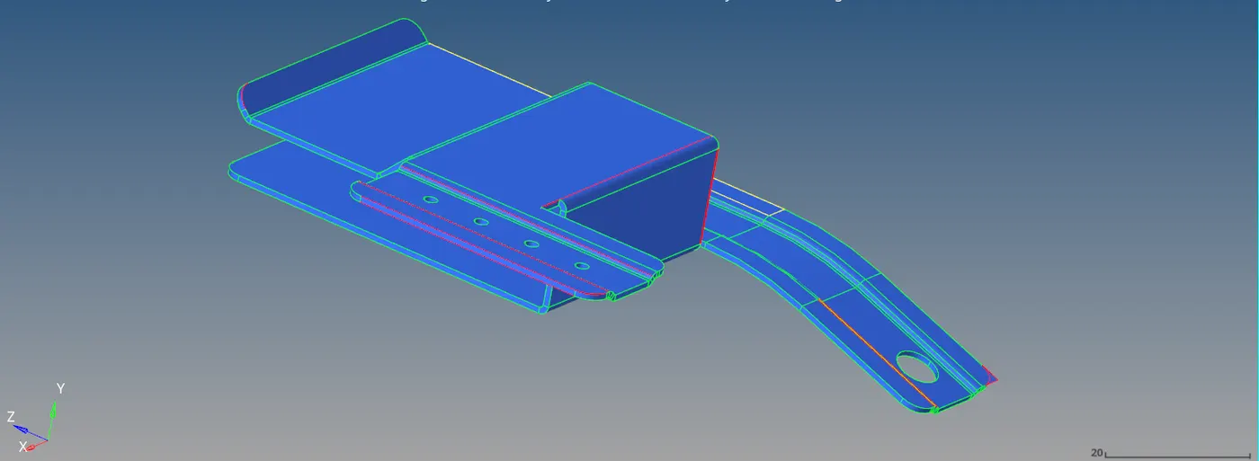
Fig 1.2: Initial model with free edges
The color coding is used to differentiate different surfaces.
- When the edge connects only one surface it is represented by red, which leads to free edges.
- When the edge connects two surfaces it is represented by green.
- When the edge connects three surfaces it is represented by yellow.
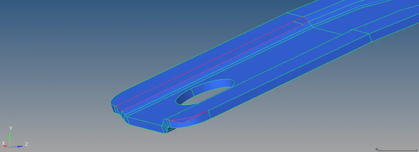
Fig 1.3: Free edge before filler surface option is used
In this section there is no connectivity between two surfaces. So filler surface option is used to rectify this free edge.

Fig 1.4: Filler surface option in Quick Edit
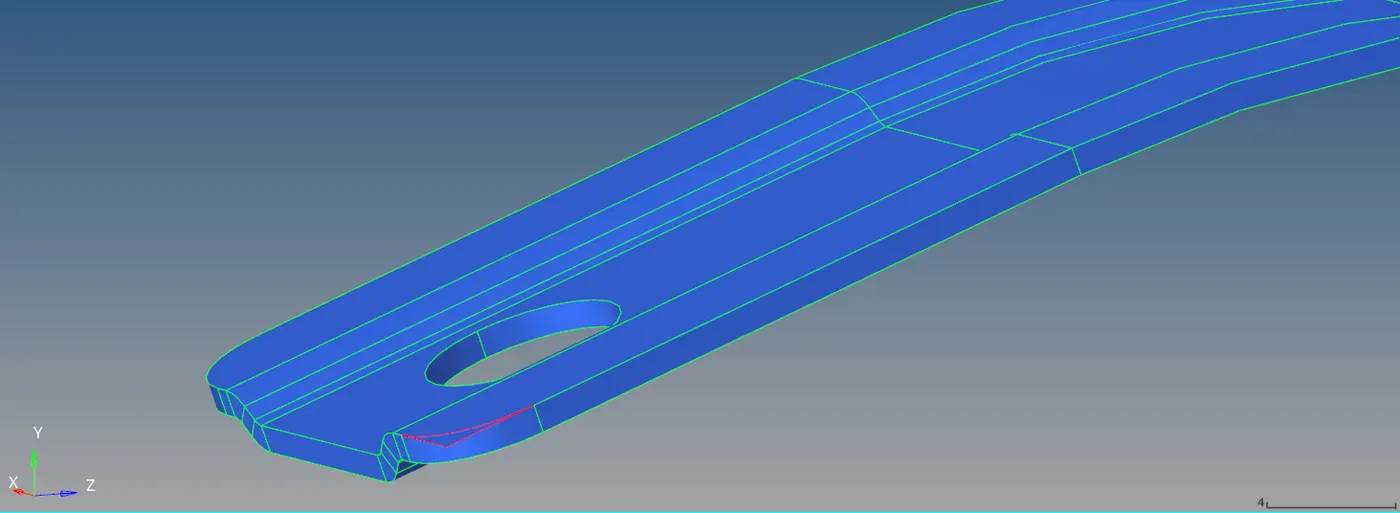
Fig 1.5: Free edge after filler surface option is used
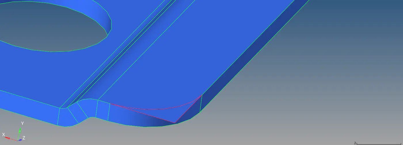
Fig 1.6: Extended edge before geometry cleanup
At one end of the model, there is edge which is extended beyond the geometry. It has to be trimmed from the model, to get rid of an extended surface and get a closed topology.

Fig 1.7: Surface trim
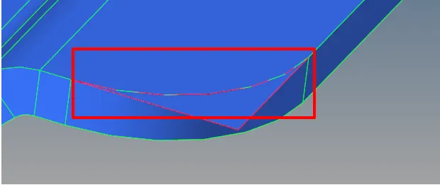
Fig 1.8: After surface trim
After the extended surface is trimmed, the extended portion is created as a new surface. It has to be deleted, to get rid of the extended surface from the model.

Fig 1.9: Delete free extended surface
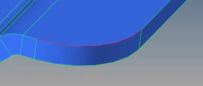
Fig 1.10: After the extended surface is deleted
After the extended surface is deleted, there is a free edge created. To close it, “toggle edge” option in the “quick edit” is used. Toggle edge option is used to close any free edges by moving them within the tolerance specified.

Fig 1.11: Toggle edge option in Quick Edit
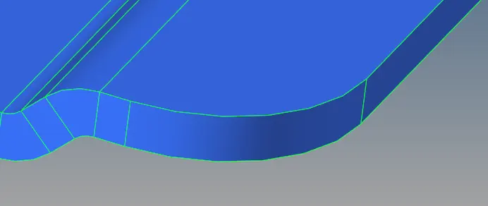
Fig 1.12: After the edge is toggled
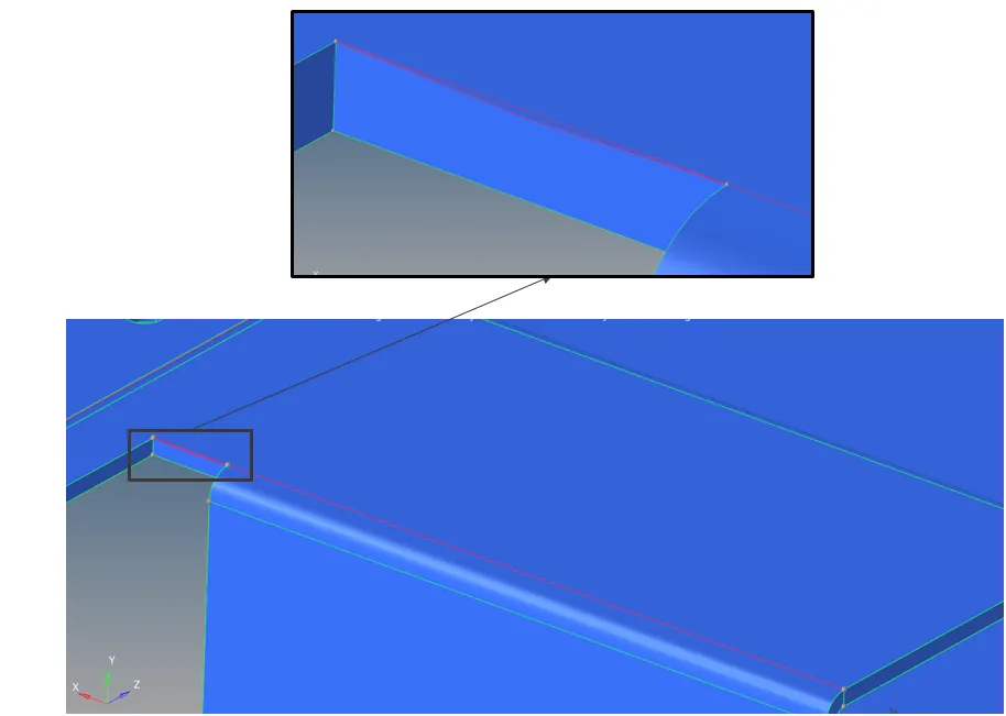
Fig 1.13: Gap between the edges
At one end of the top of the component, there is a gap between the actual edge and an extra edge. The toggle edge option is used to close this gap. Since the gap is high, higher value is used as the tolerance.
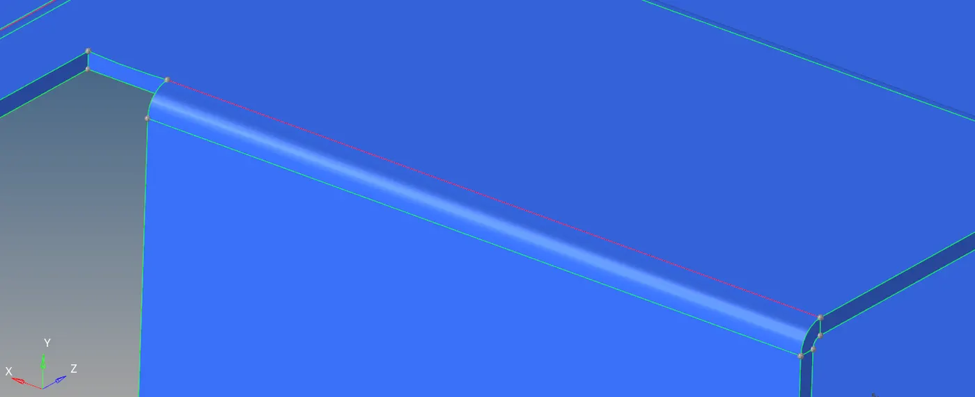
Fig 1.14: Free edge at the top of the model
There are few free edges at the top of the mode. Toggle edge option is sued to close the free edges.
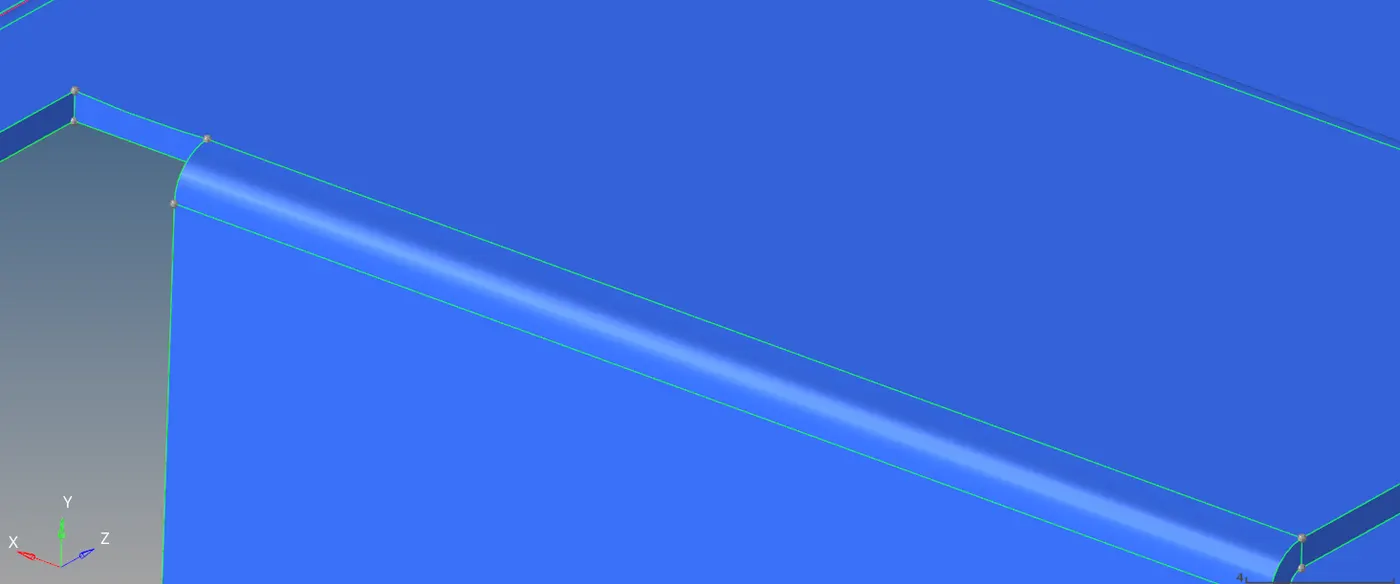
Fig 1.15: Toggled edge
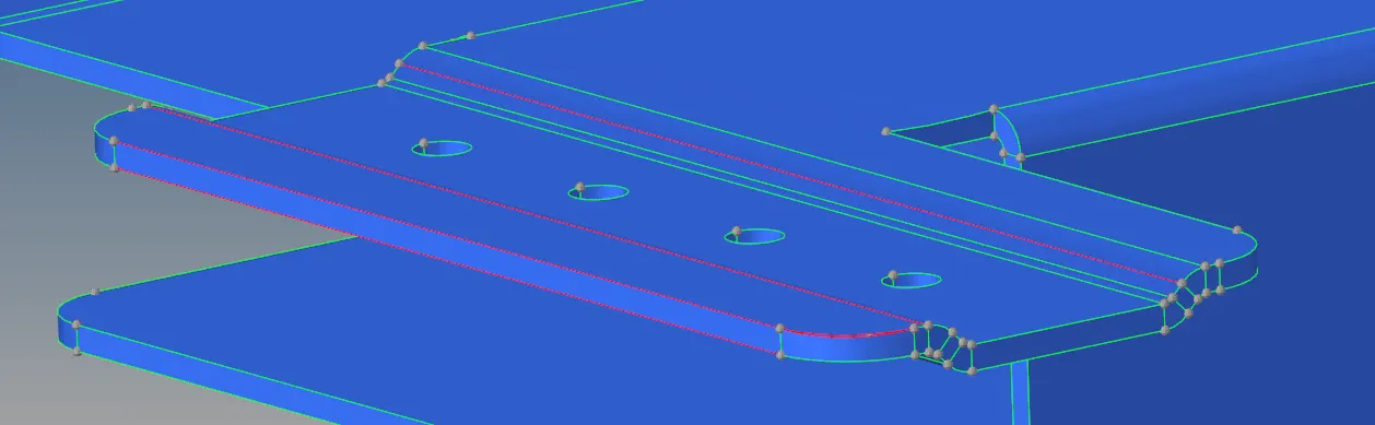
Fig 1.16: Free edges
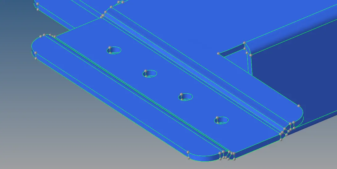
Fig 1.17: Toggled edges
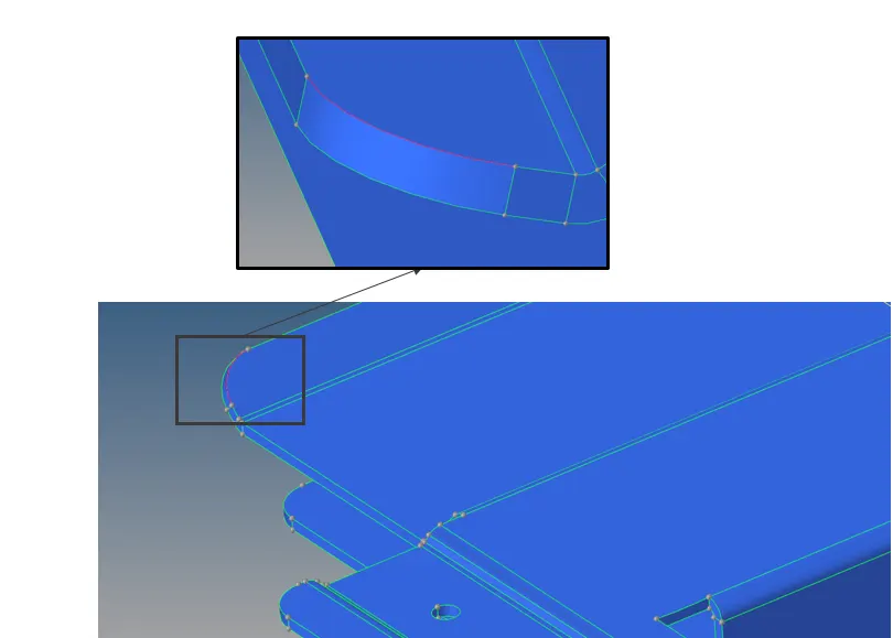
Fig 1.18: Free edge
The free edge at the end is removed by using the “toggle” option from the “edge edit” using the cleanup tolerance of 0.001.
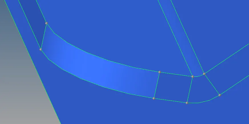
Fig 1.19: Free edge
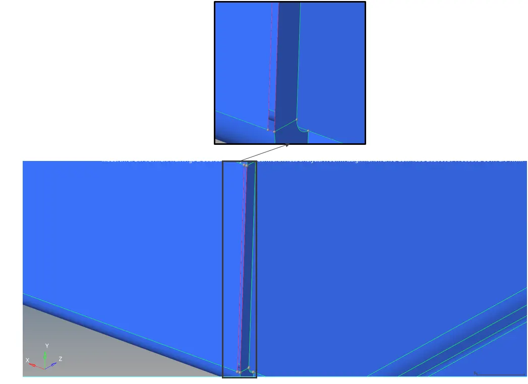
Fig 1.20: Unnecessary Edge
The model has an unnecessary extra edge, which does not neither have any meaning nor any use to the functionality of the component. It has removed from the model. This can be done by replacing one line (inside line) with the outside line by retaining the outside line.

Fig 1.21: Replace edge option from edge edit
The inside edge is selected as the moved edge and the outside edge is selected as the retained edge. The cleanup tolerance is increased to match the gap between both the lines. The distance between both the lines is measured to be 2.003e-01.
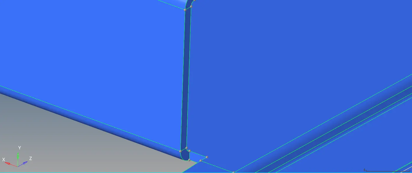
Fig 1.22: After replaced one edge with the other edge
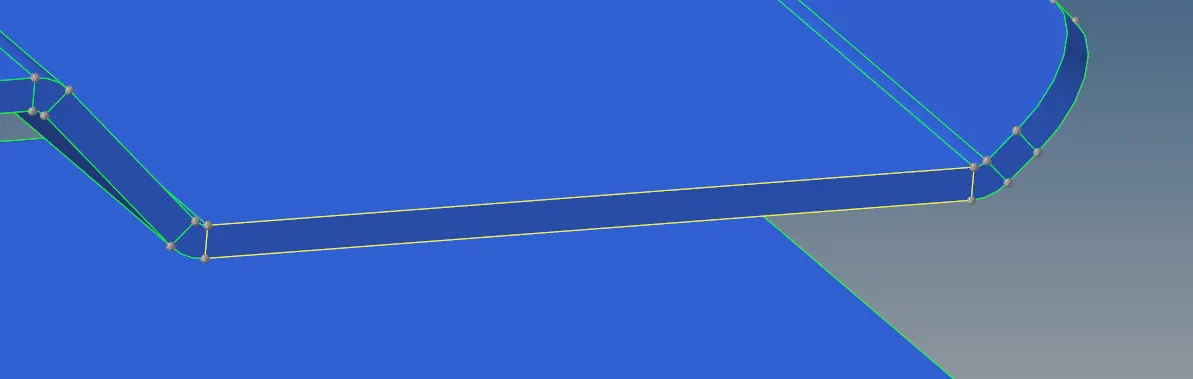
Fig 1.23: Edge connecting three surfaces
At one end of the model there are edges which connects three surfaces. It may be due to the duplicate surface present at the same location. The extra surface has to be removed. Thus, the supplicate surface lying on the original surface is deleted using the “delete surface” option.
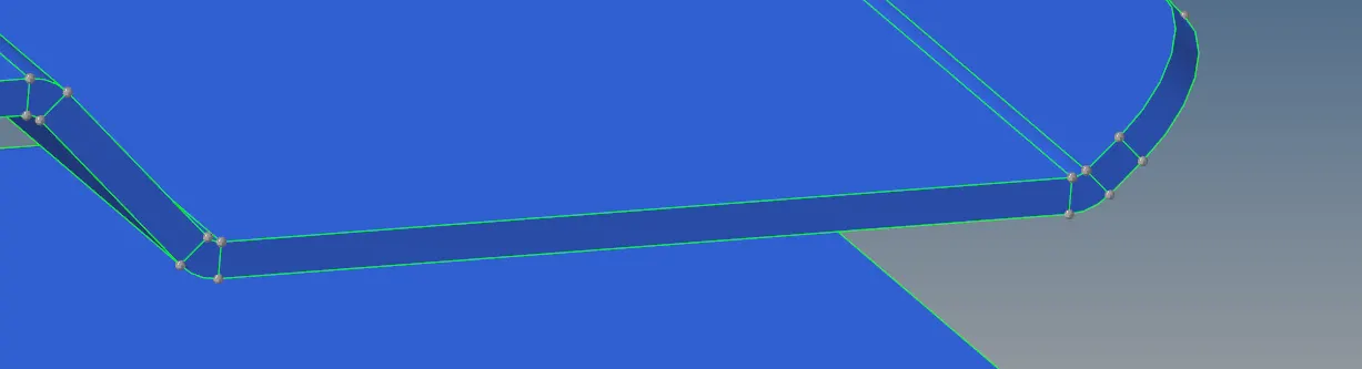
Fig 1.24: After the edge is deleted
There is the same problem of extra surface at the other surface of the model too. It is also deleted to get a closed surface.
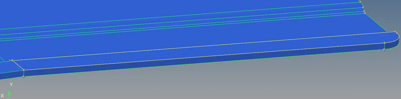
Fig 1.25: Edge connecting three surfaces
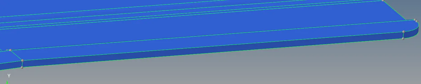
Fig 1.26: After the edge is deleted
The model is cleaned from all the free edges, to make a topology with perfect connections. Now the model is ready for mid-surface extraction.
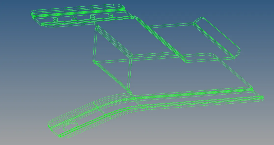
Fig 1.27: After geometry clean-up
Midsurface Extraction:
Few components especially thin sheet metal components are meshed using shell elements, instead of using the solid elements, which considerably increase the number of nodes and computational time. To use shell elements, midsurface has to be extracted. For thin-walled components, the midsurface is meshed using the shell elements.
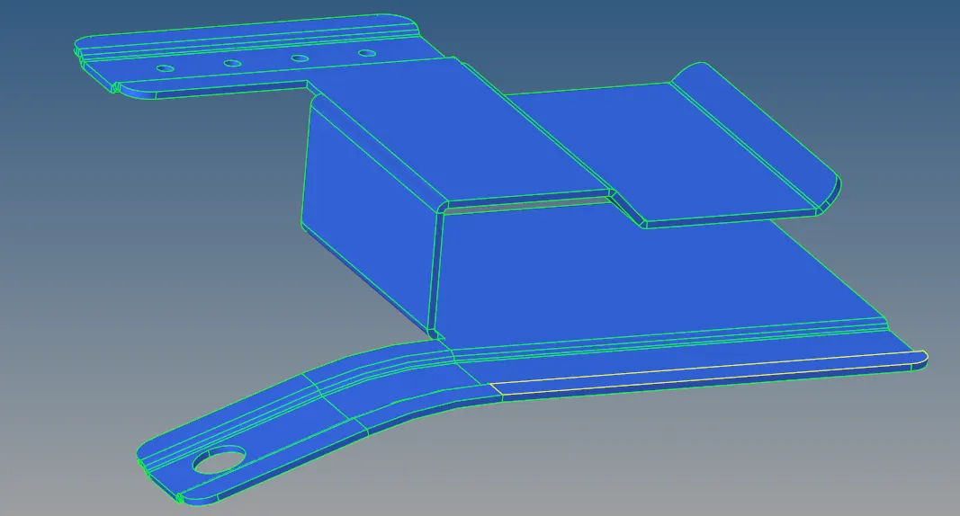
Fig 1.28: Clean component for which midsurface has to be extracted

Fig 1.29: Midsurface extraction
The cleaned closed surface of the component is chosen to extract the midsurface automatically.
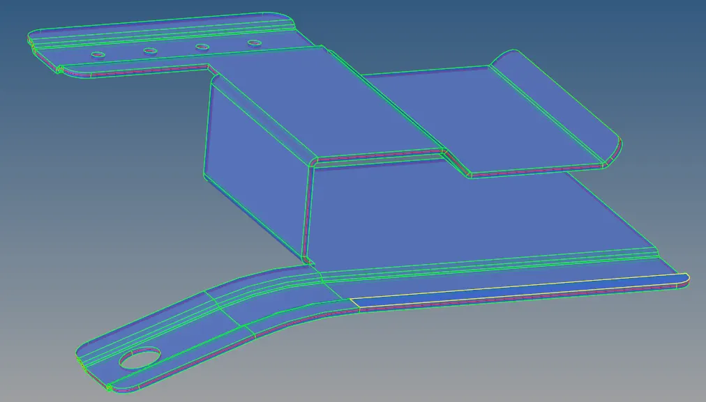
Fig 1.30: Extracted midsurface
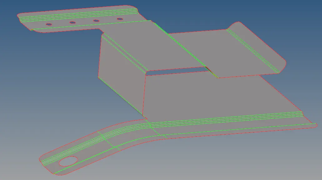
Fig 1.31: Extracted midsurface
Midsurface cleanup:
When the midsurface is created, there is a small deviation from the original geometry.
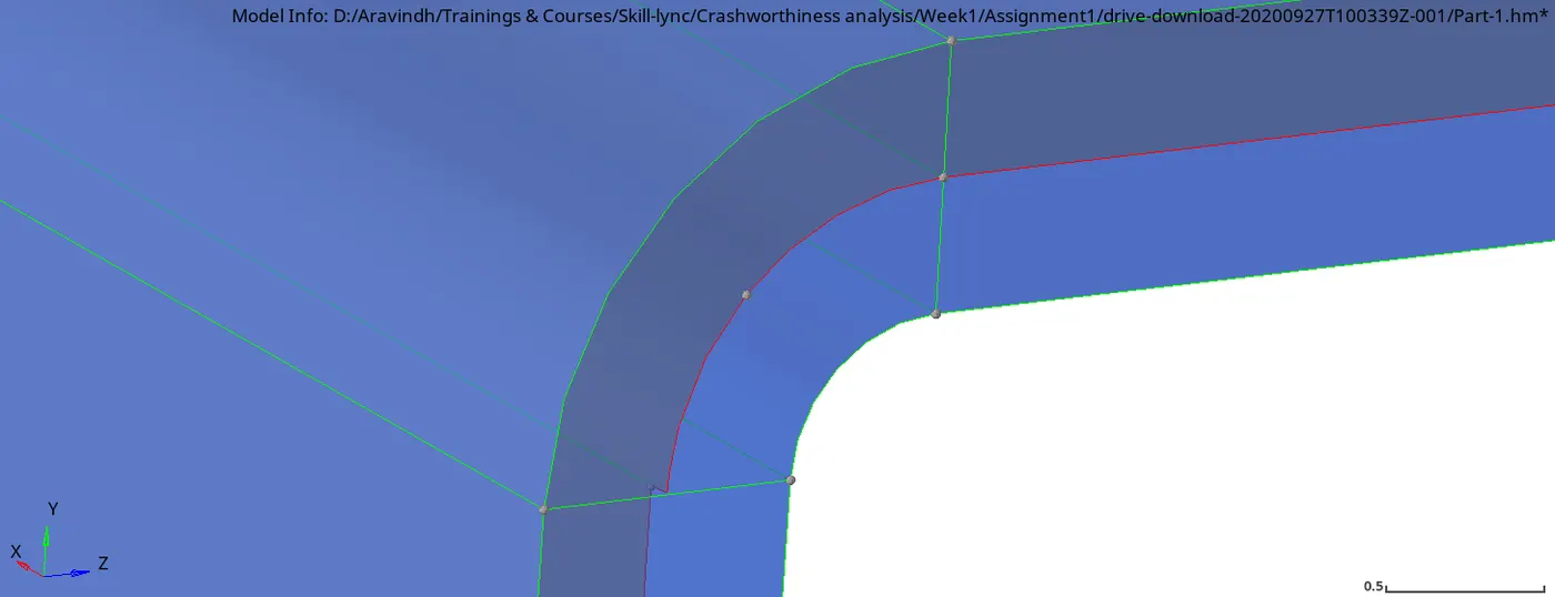
Fig 1.32: Midsurface deviation
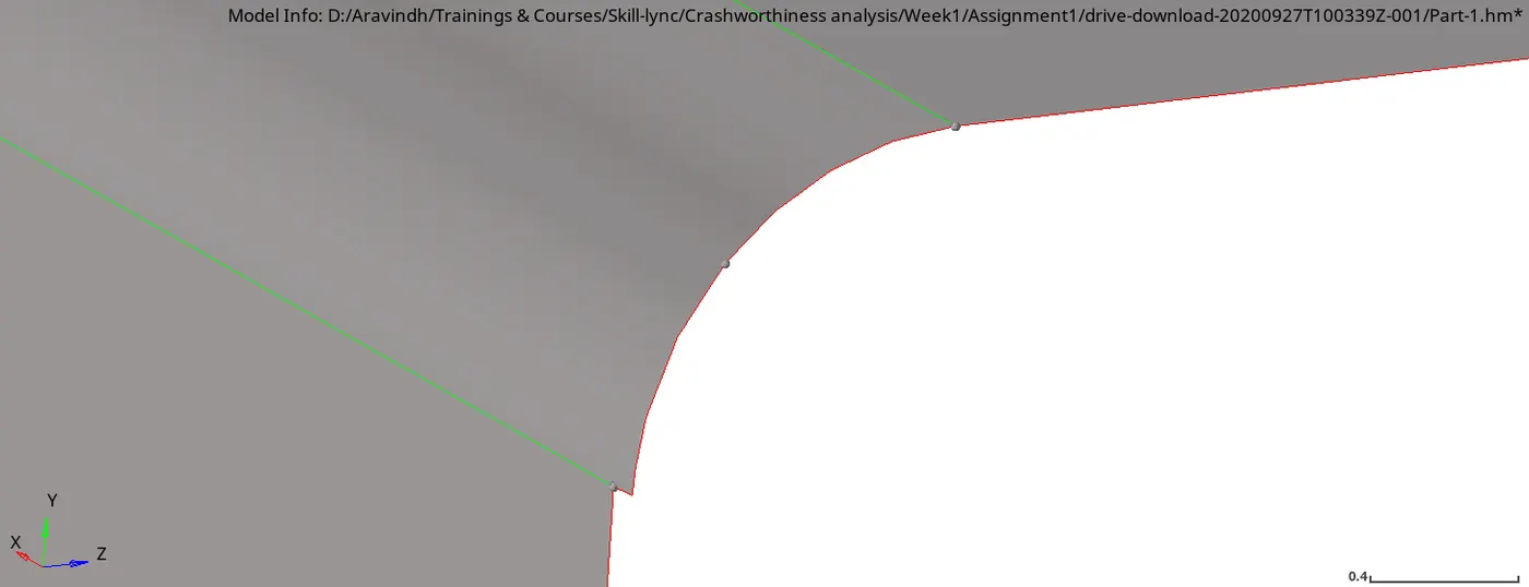
Fig 1.33: Midsurface deviation
It is corrected by geometry-cleanup operation. “Replace point” tool from quick edit option is used, to move from one point to other.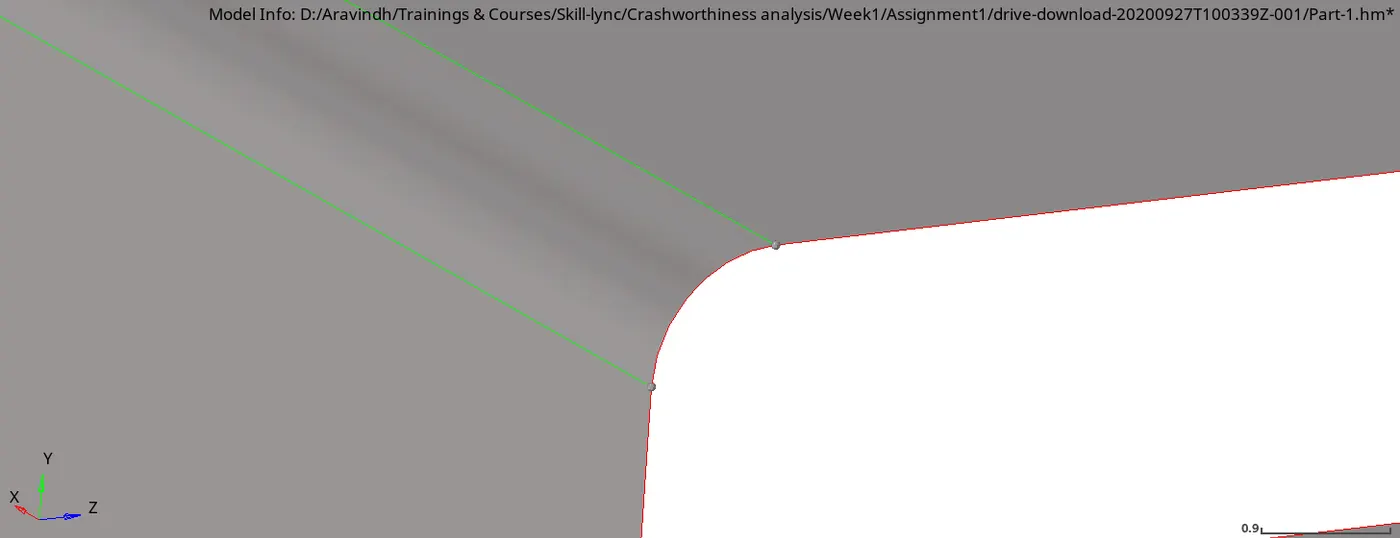
Fig 1.34: Midsurface corrected
According to one of the objective of the task, the holes with the diameter less than 5 mm has to be neglected. The measurements of the holes in the model are checked. So three nodes option is used in the “distance” tool in the Geometry option. Initially the diameter of the holes on the top is measures.
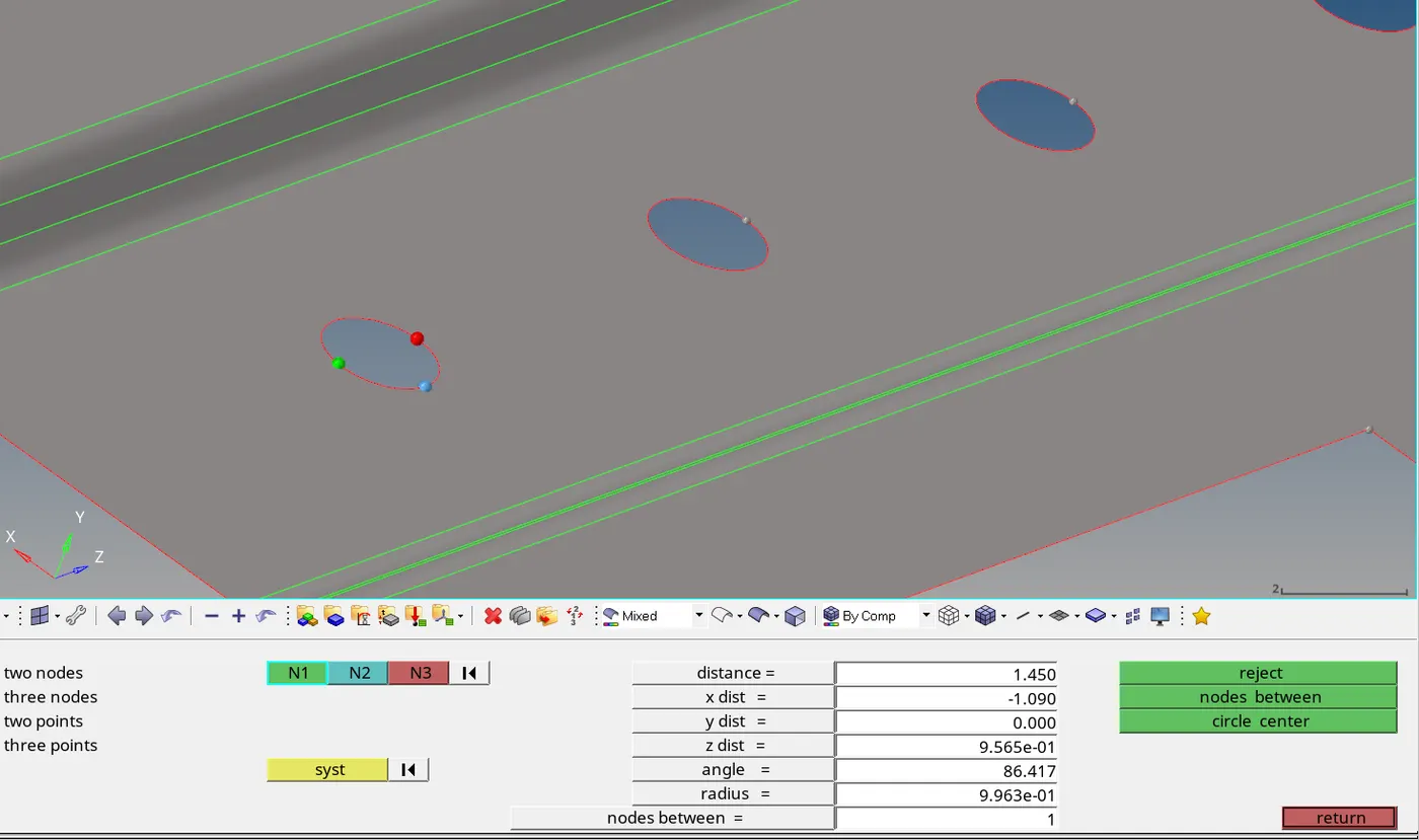
Fig 1.35: Radius of the circles on the top
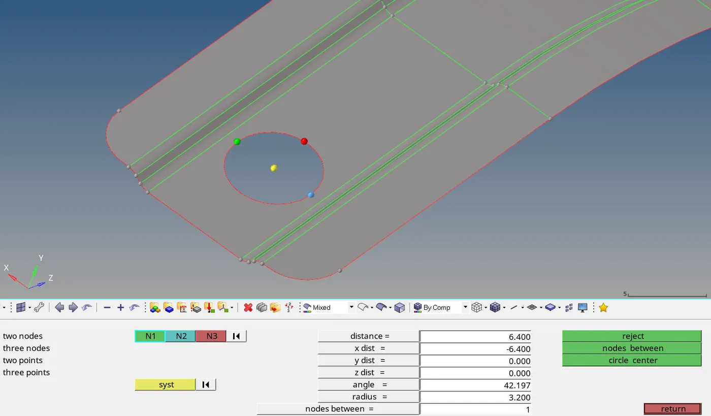
Fig 1.36: Radius of the circles on the bottom surface
In the model there are 4 holes on the top has the diameter less than 5 mm. It has to be closed before starting the meshing process. The hole at the bottom has the diameter of 6.4 mm.
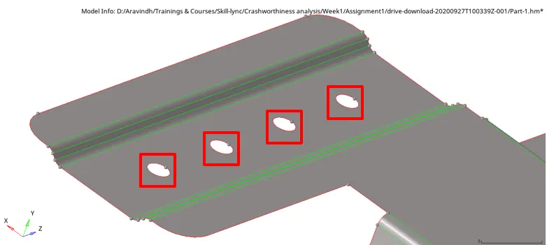
Fig 1.37: Holes with diameter less than 5 mm
“Filler surface” or the “unsplit surf” tool from the quick edit option is used to fill the holes. When the filler surface option is used, it will leave the edge of the hole on the model itself. To avoid that, “unsplit surf” tool can be used. “unsplit surf” tool is used here to remove the edges also.
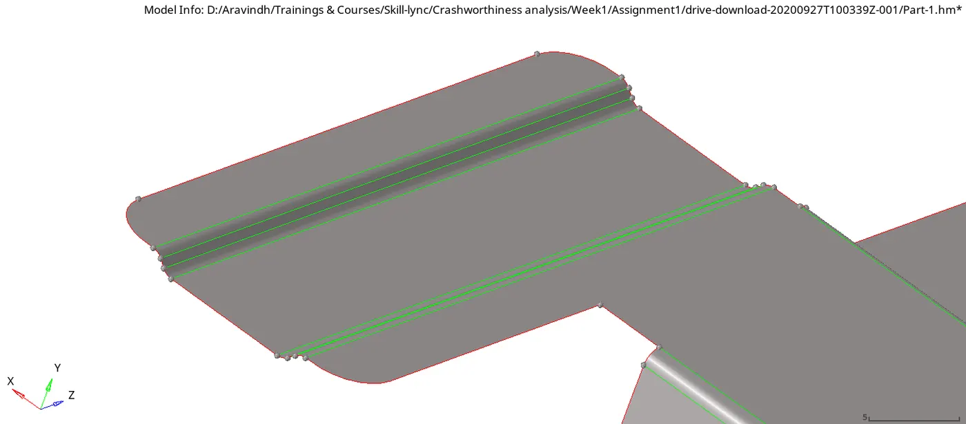
Fig 1.38: After the holes are closed
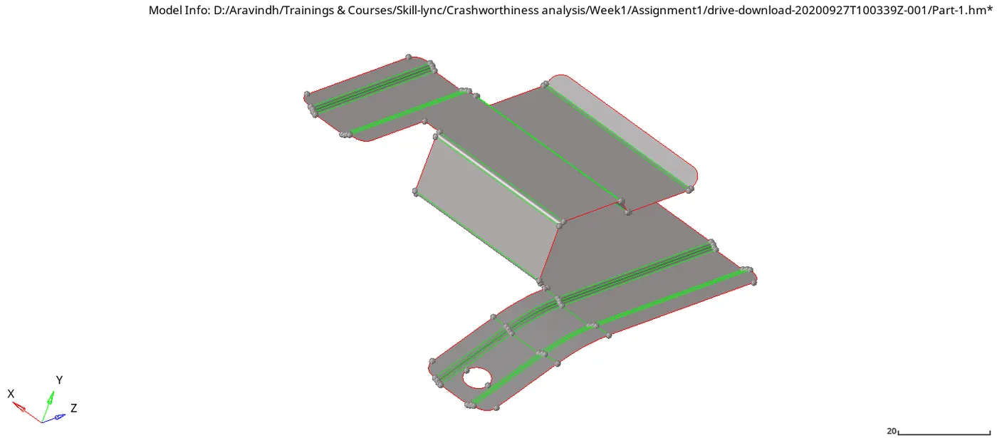
Fig 1.39: Complete model after the clean-up operations
Now the model is completely ready for meshing.
Meshing:
2D shell mesh is used. The main of the meshing this components are as follow:
- Try avoiding the 3 node triangular shell element in the model as possible. The reason is that the quad element gives better mesh flow and also the main disadvantages of the trias. The trias are stiffer and also can lead to high stress concentration, which has to be avoided to get more accurate result.
- Get the mesh with good element quality criteria.
- Target mesh size of 5 mm, with the minimum length 3 mm and maximum length 7 mm.
The mesh is started from the middle of the component using “automesh” tool from 2D option with the element size of 5 mm.

Fig 1.40: Automesh options
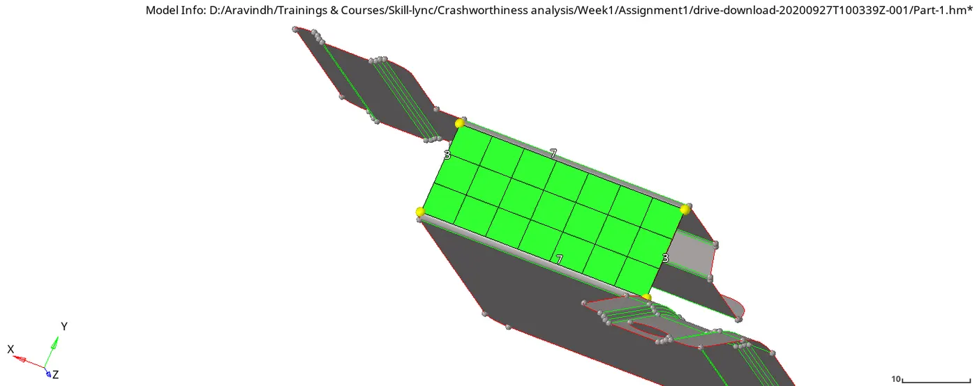
Fig 1.41: Meshing the middle of the component
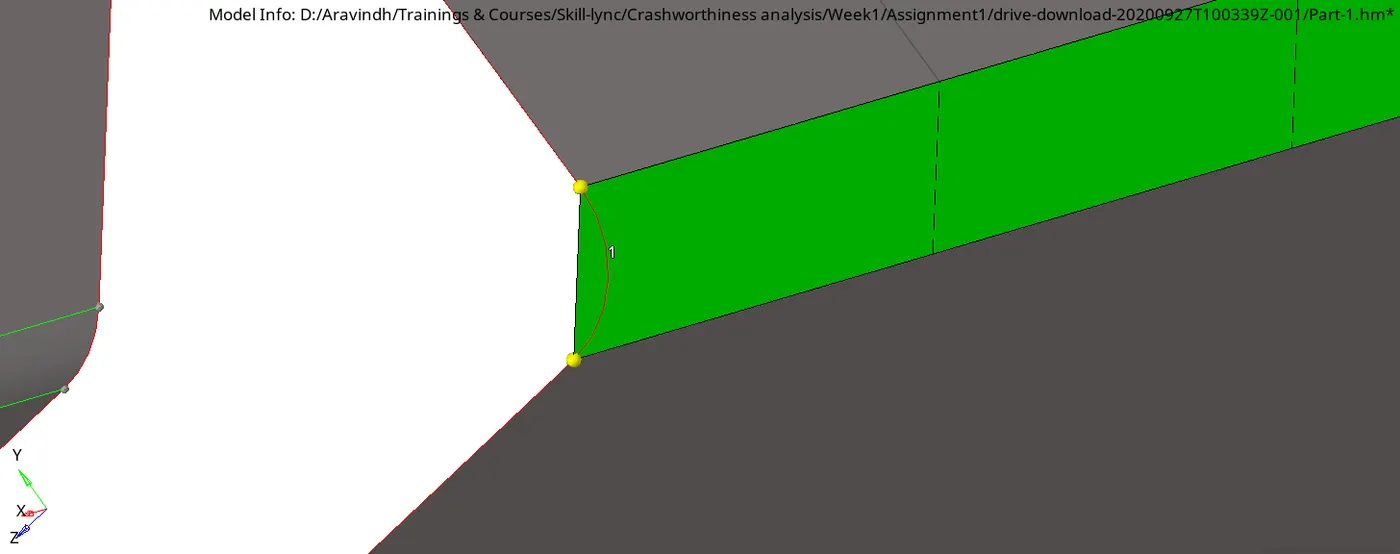
Fig 1.42: 1 element along the fillet
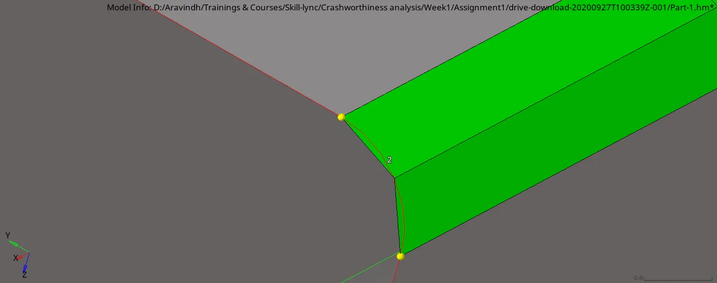
Fig 1.43: 2 elements along the fillet
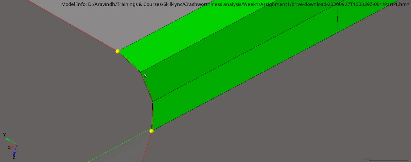
Fig 1.44: 3 elements along the fillet
From the figures 1.42 to 1.43, it can be seen that the 3 element along the fillet gives better mapping of the fillet. Good mapping of fillet is necessary. Fillets are introduced in a geometry to avoid sharp corners, which will lead to high stress concentration in the geometry when the load is applied. It may eventually lead to crack at the corner and complete failure of the component. So the mesh at the fillets have to be as smooth as possible by considering the total number of elements in the model, element type and simulation time. Since here 2D 4 node shell element is used and also since the total number of elements is very less for entire model, 3 element along the fillet is used. The simulation time won’t vary much. But the results will be much more accurate.+
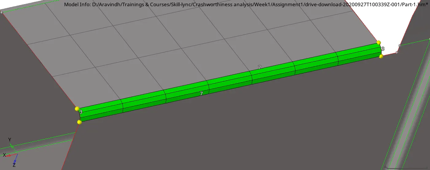
Fig 1.45: Mesh along the fillet
The bottom surface is meshed using the element length of 5 mm. The mesh generated did not have a good mesh flow, which is an important criteria for a good quality mesh, as it distributes the energy during the simulation due to load more effectively and accurately without any local stress concentration. To achieve that, the mesh is refined again and again, till the good mesh flow is achieved.
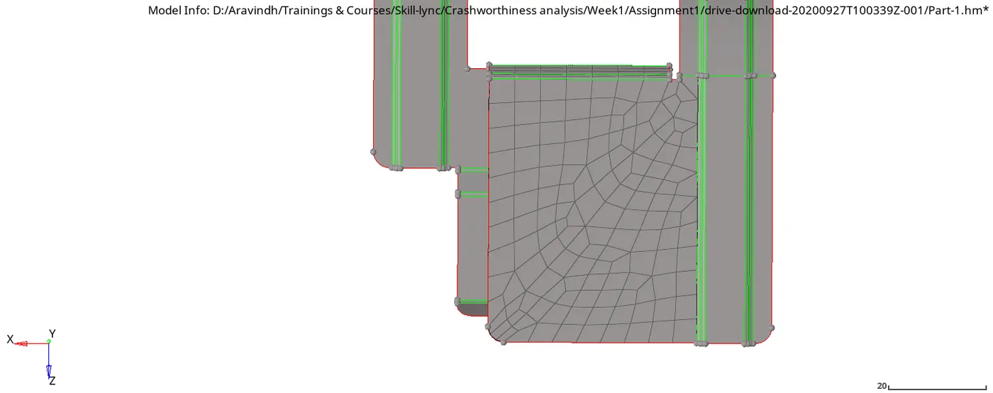
Fig 1.46: Mesh at the bottom surface
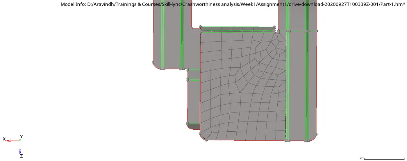
Fig 1.47: Refining mesh
To map the fillet more correctly, element length of 4 mm is used near that area.
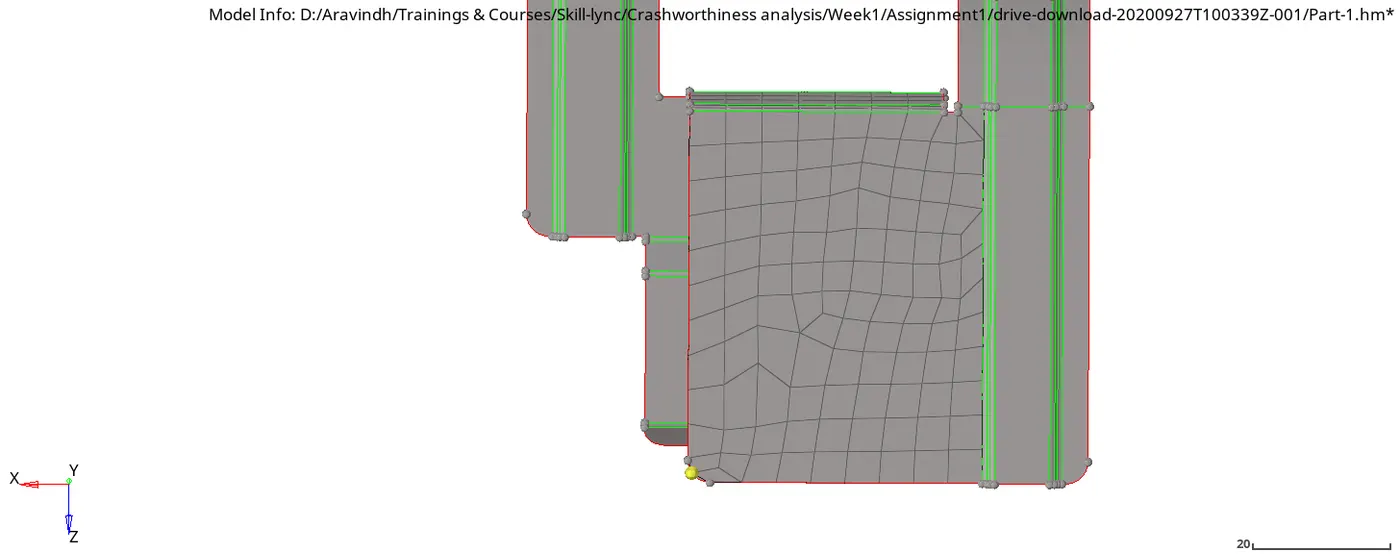
Fig 1.48: Small element length at the bottom near fillet
After that the mesh is again remeshed to achieve good mesh flow.
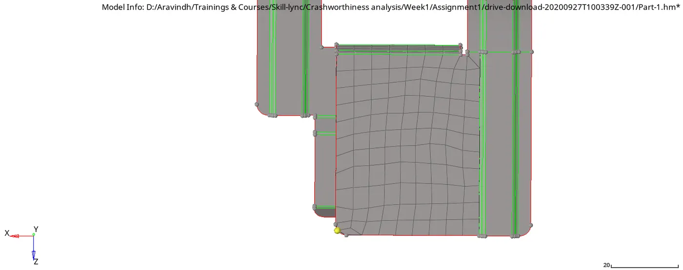
Fig 1.49: Refining mesh
Even after the sufficient remeshing, there are few edges which are not straight. In order to get more good mesh, “smooth” tool from 2D option is used with few iterations, to straighten up element edges.

Fig 1.50: Smooth
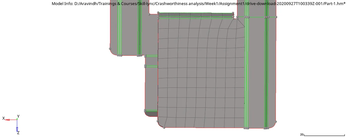
Fig 1.51: Final mesh at the bottom surface
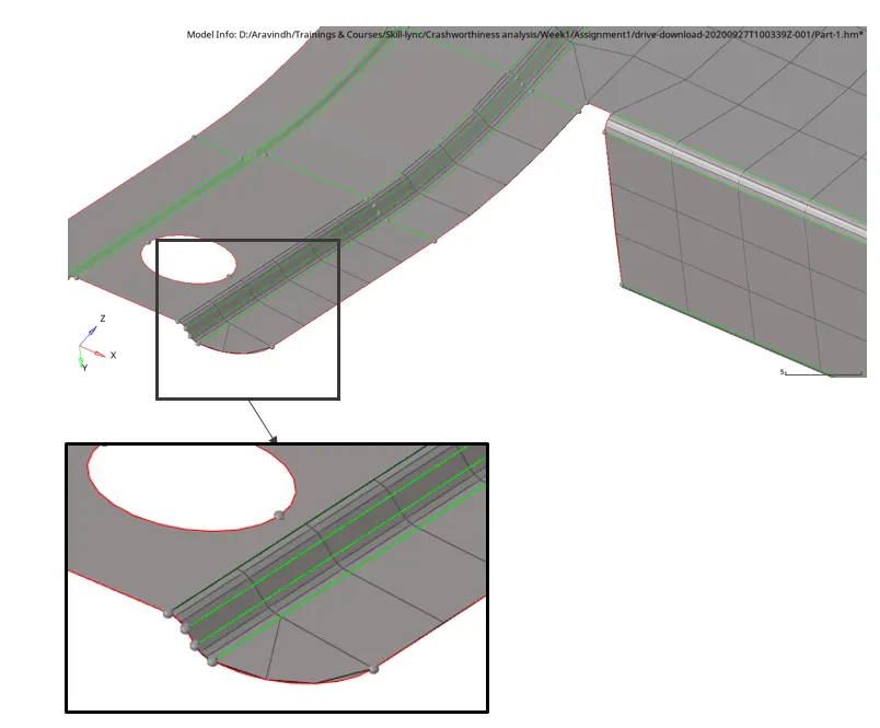
Fig 1.52: Mesh at the corner bottom surface
The remaining small section of the bottom surface is meshed and edge is refined a little to get an accurate map of edge fillet. For the surface fillet 3 mesh along the fillet is used for better map.
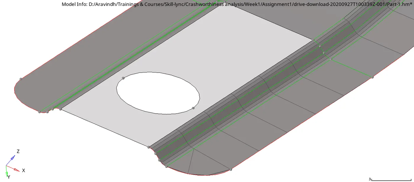
Fig 1.53: Bottom surface with hole
In the next bottom surface, there is a hole. For holes “washer surf” tool in quick edit option is good method to avoid stress concentration near the hole due to poor mesh. But here, since the distance between the hole and the surface edge is very small, it will result in very small washer surface, which in turn lead to very small elements. So the “washer surf” tool is not used.
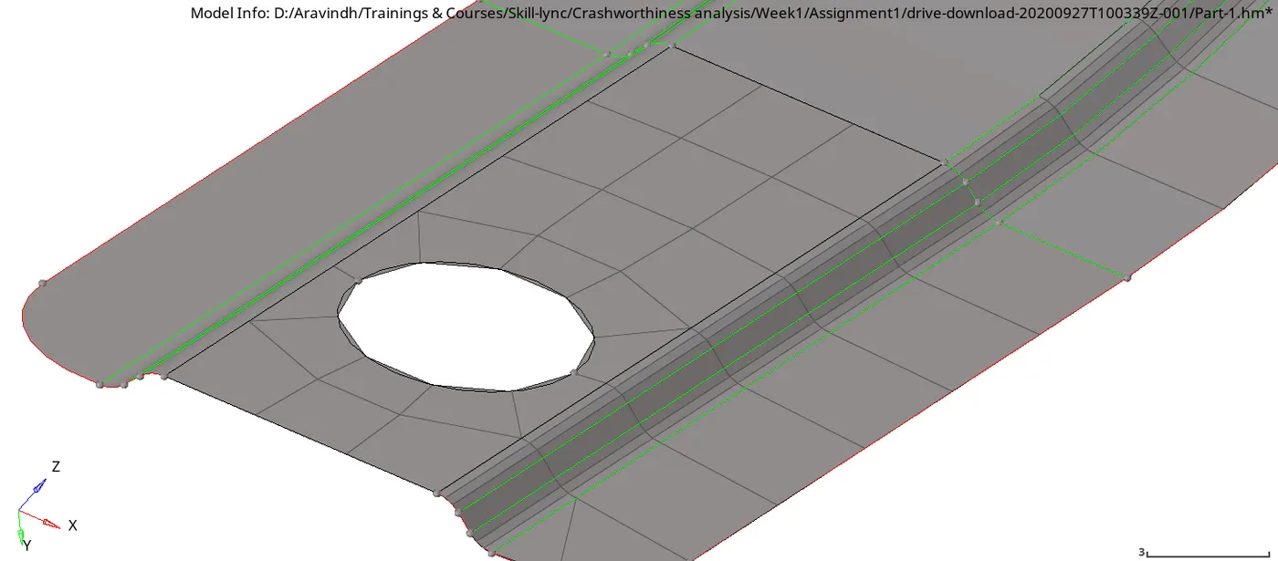
Fig 1.54: Mesh at bottom surface near the hole
In order to avoid stress concentration at the hole, 10 nodes are chosen along the edge of the hole and the same number of nodes at the bottom and top edge of the surface is chosen to get the quad element with better mesh flow. To refine it further and get better mesh flow for an element size, smooth option is used. It increased the element size near the hole and made it somewhat same as that of other elements in the same surface.
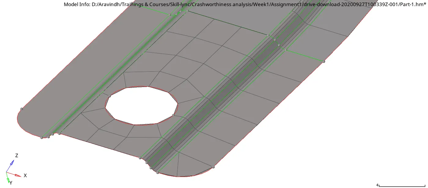
Fig 1.55: Mesh after smooth
The remaining of the bottom surface is meshed similarly.
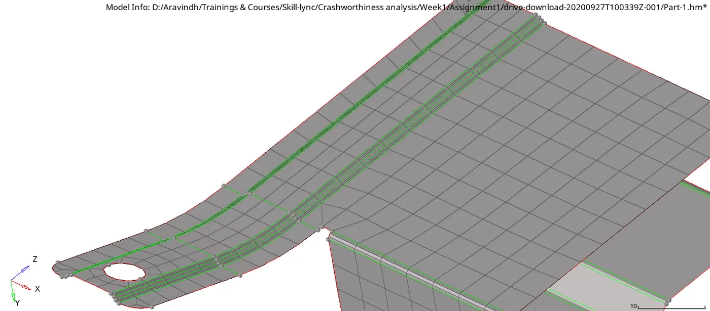
Fig 1.56: Complete mesh of bottom surface
At edge to get a good profile of the fillet and also to avoid the trias, number of nodes is increased at the fillet to get two quad nodes.
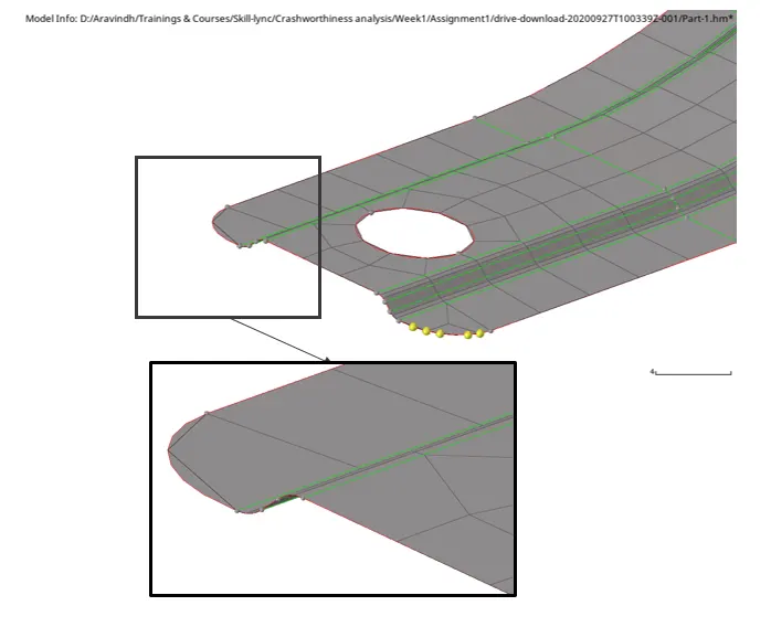
Fig 1.57: Initial edge node
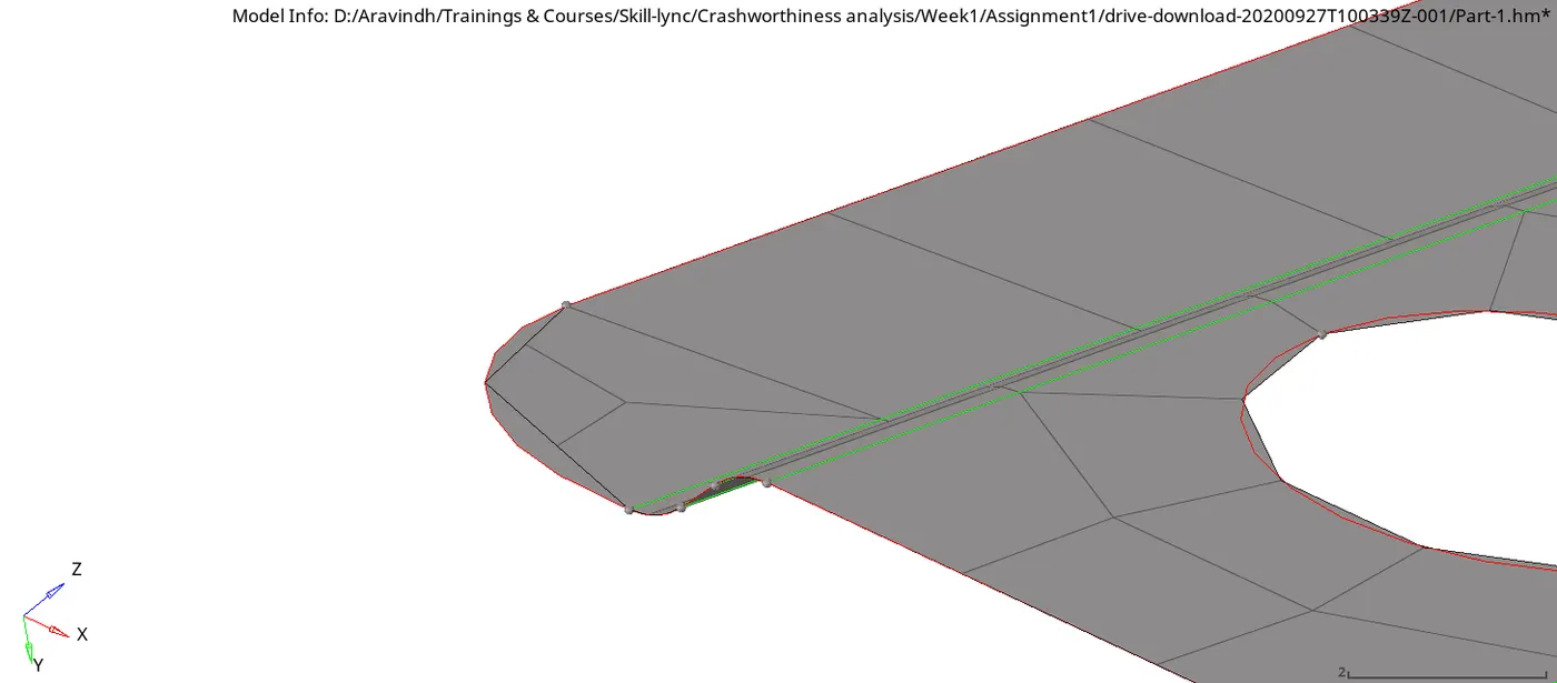
Fig 1.58: After increasing the number of nodes
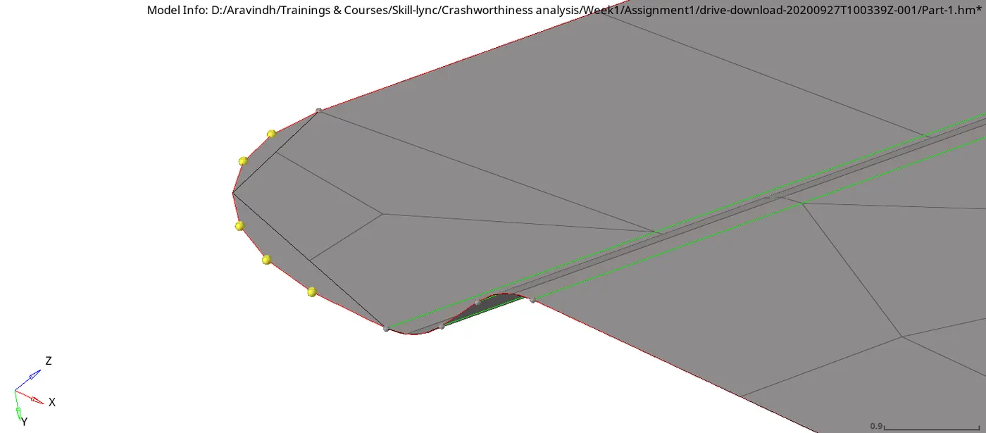
Fig 1.59: Nodes created at the surface of the fillet

Fig 1.60: Node equivalence
The element nodes are move to the suitable surface nodes, to get good mesh of the fillet. By this method two quads are used instead one quad with poor representation of original surface and one quad and one tria to avoid stiff element at the corner.
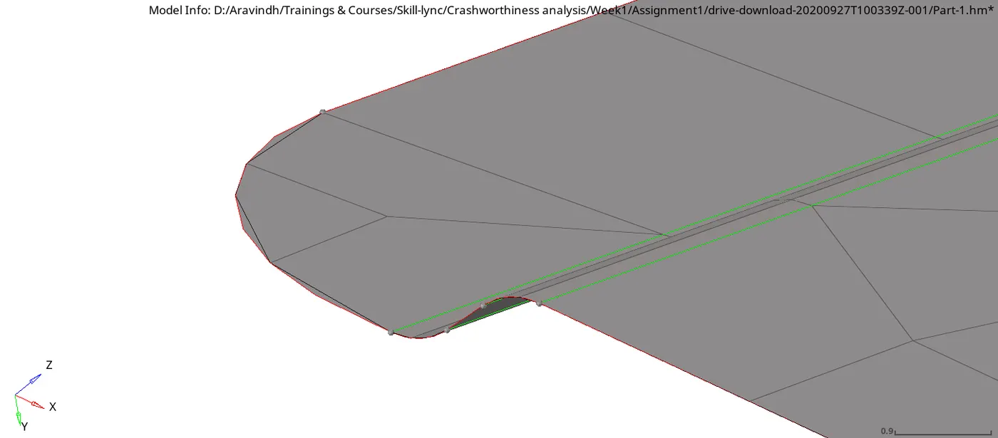
Fig 1.61: Final mesh at the edge fillet
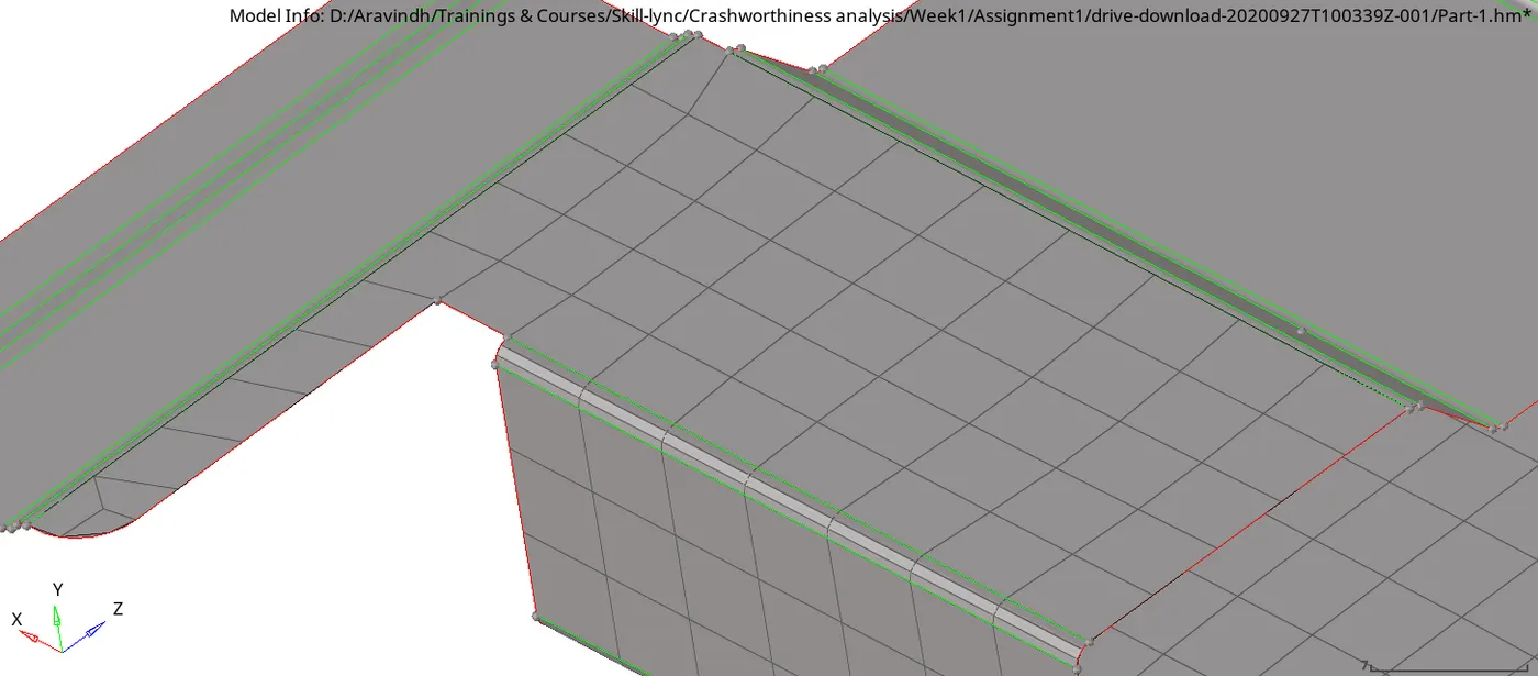
Fig 1.62: Final mesh at the top surface before smooth
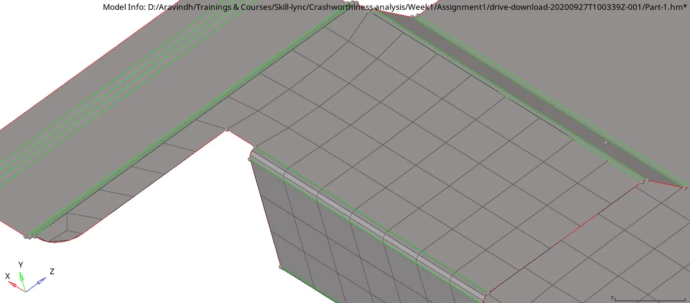
Fig 1.63: Final mesh at the top surface after smooth
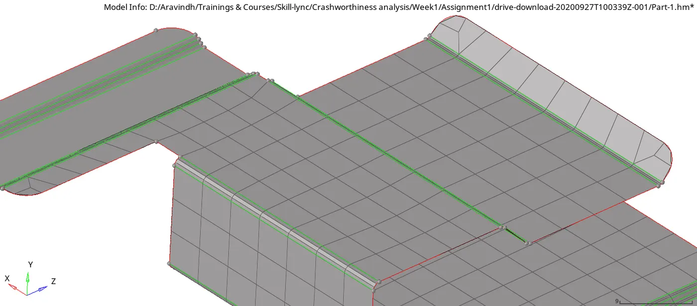
Fig 1.64: Final mesh at the top surface
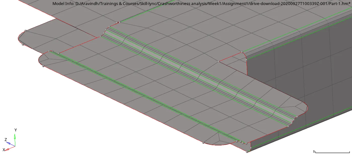
Fig 1.65: Final mesh at the side of the top surface
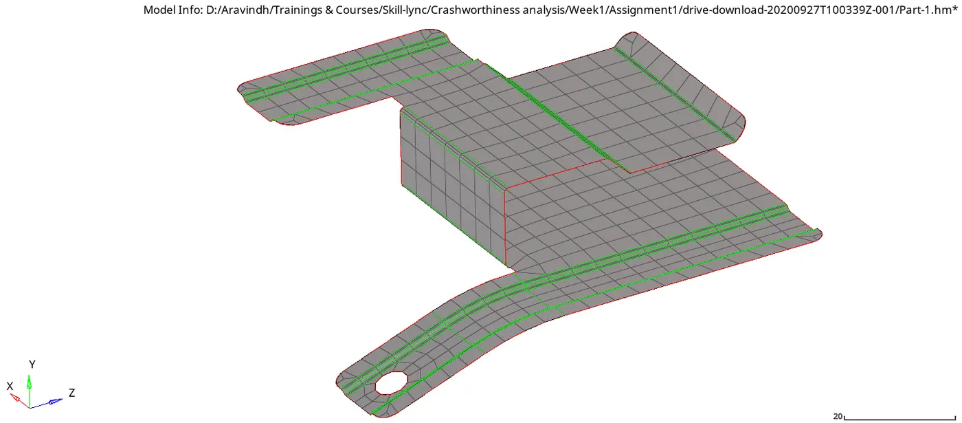
Fig 1.66: Final mesh of the component with surface edges
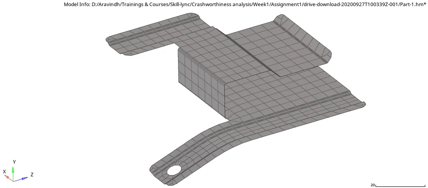
Fig 1.67: Final mesh of the component without surface edges
Element Quality:
- Shell normal:
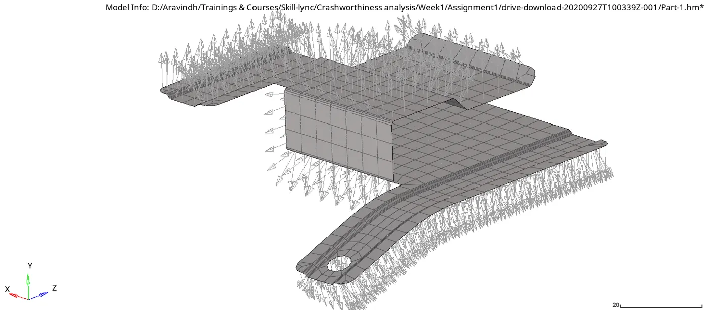
Fig 1.68: Surface normal of the elements
The surface normal of the shell elements are important. The normal of all the elements has to be in the same direction. Here, the normal of all the elements on the outer surface are pointed out.
- Duplicate elements:
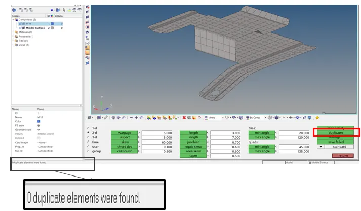
Fig 1.69: Duplicate elements
-
Element quality:
The quality of the element is checked, by specifying the target values such as maximum and mainimum element length, Jacobian, aspect ratio, Skew etc.
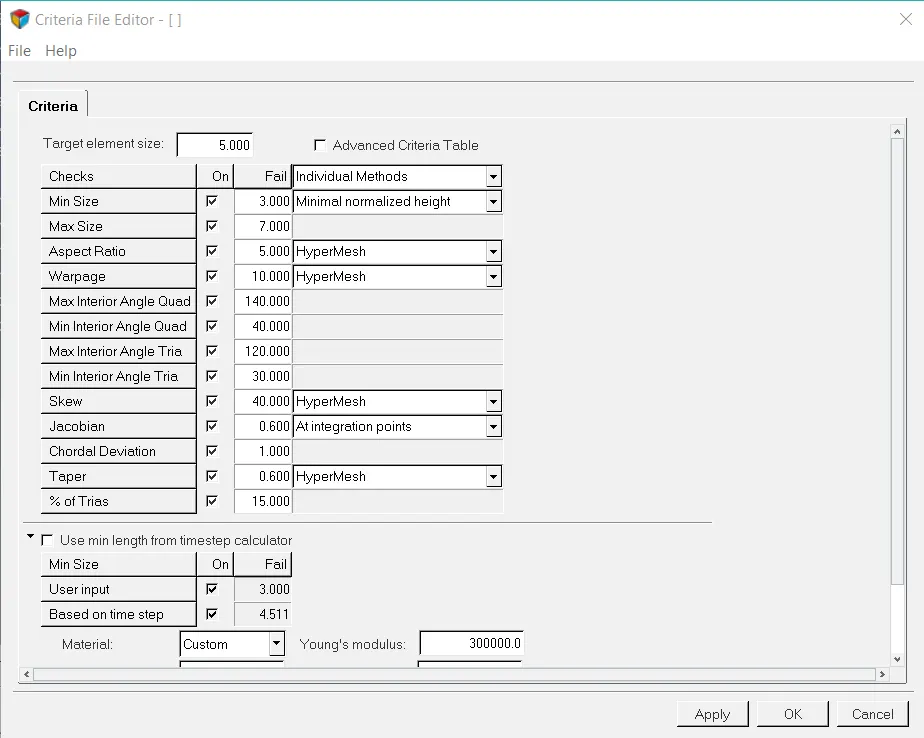
Fig 1.70: Quality criteria
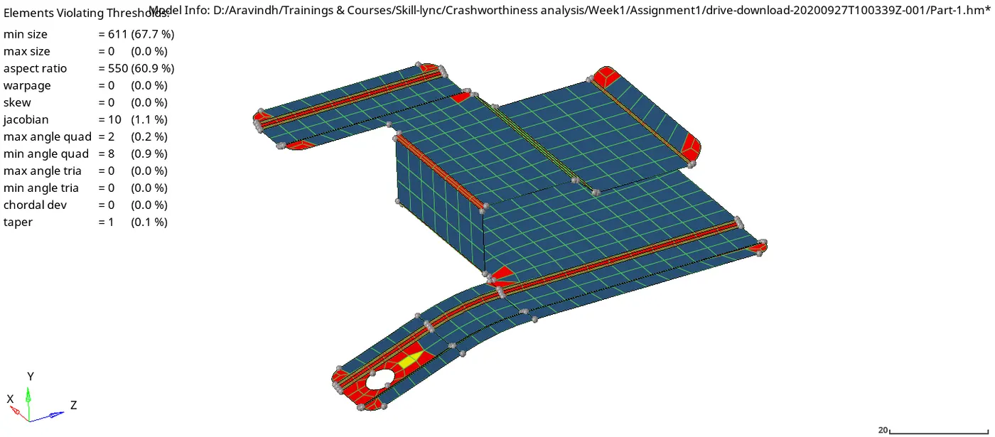
Fig 1.71: Quality criteria results
From the results, it can be seen that the minimum element length criteria and the aspect ratio cannot be met at many areas. Since the geometry has many fillets and surface fillets, small elements had to be used in these areas to get better mesh flow. Therefore the minimum element length cannot be met. Because of the same reason the aspect ratio cannot be met. To map fillet small elements were used. Bu one dimension of the element was high compared to other dimension. If that dimension is also reduced, the element size has to be reduced throughout the element, thereby increasing the number of elements considerably.
Thickness:
A property is created for the midsurfce using P1_SHELL card and thickness of 0.91 mm.
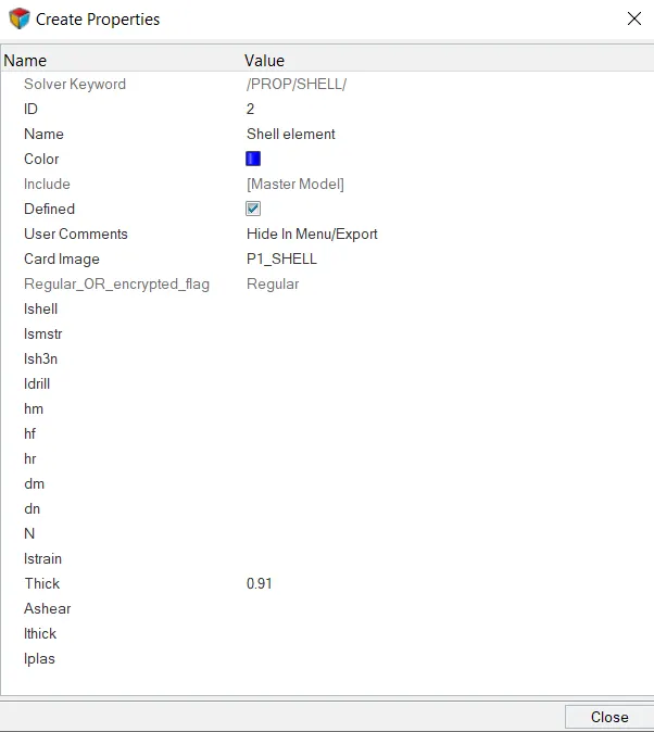
Fig 1.72: Property
Part 2 - Clip Repair:
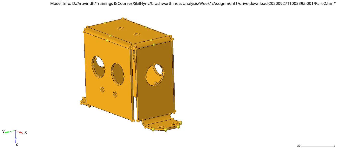
Fig 2.1: Component
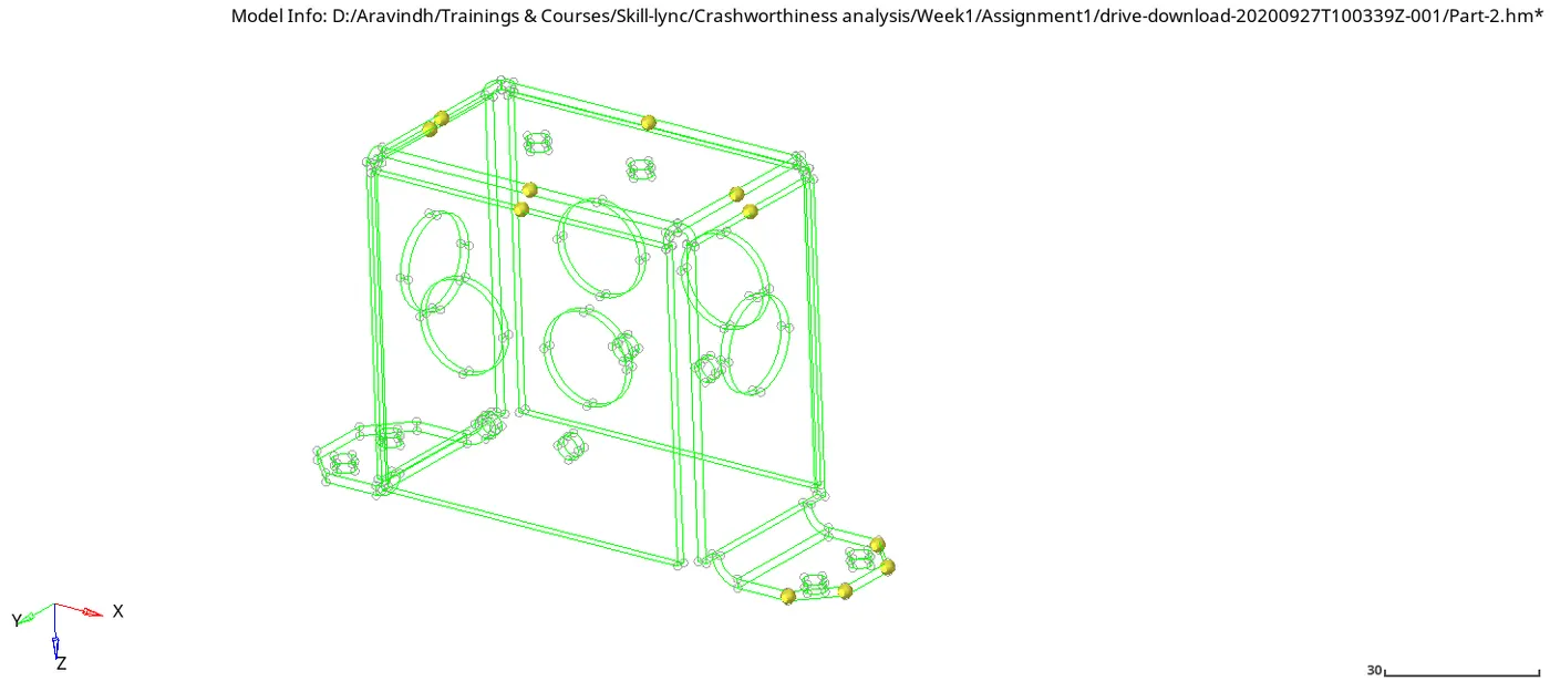
Fig 2.2: Edges
There are no free edges in the component. So the midsurface can be extracted directly.
Midsurface:
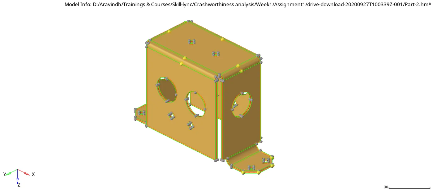
Fig 2.3: Midsurface with component surfaces
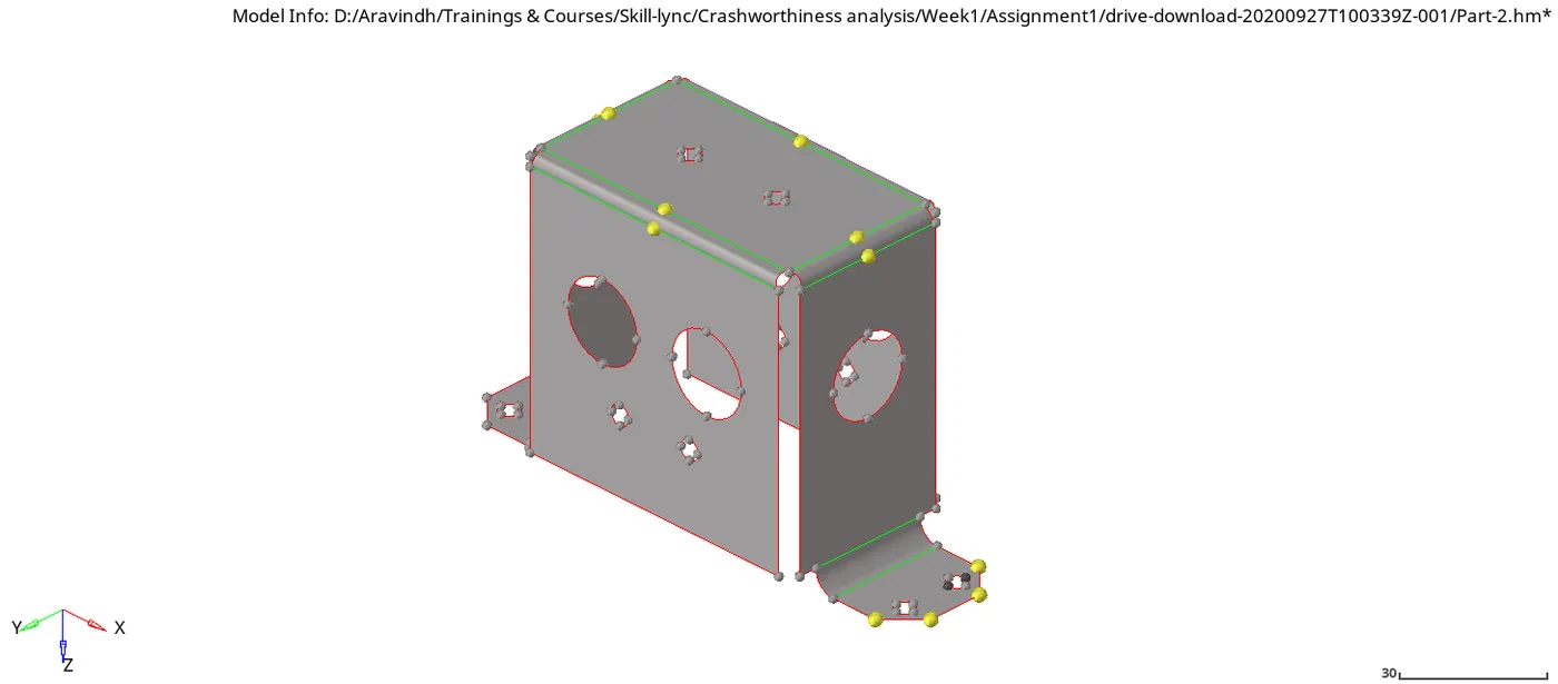
Fig 2.4: Midsurface
Cleaning Midsurface geometry:
In this component the diameter of all the holes are either 5 mm or above 5 mm, all the holes are considered.
But at the top surface near to surface fillet, there are 2 points. When meshing, it will give rise to one extra element or the element will be far from ideal shape of regular quad, which will give rise to Jacobian error at the end. Thus they will joined together to avoid above mentioned problems. One point will be replaced with other using “replace point” option in quick edit menu.
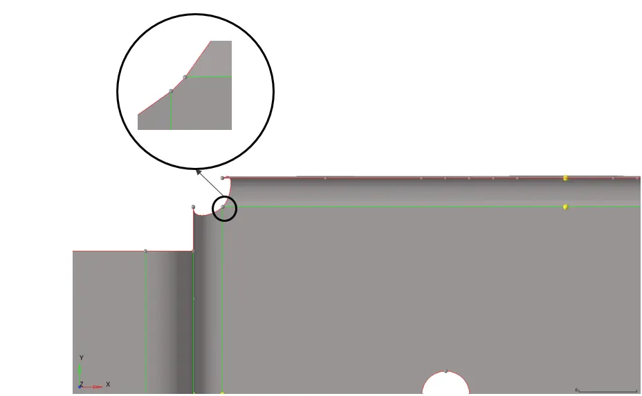
Fig 2.5: Edge points#
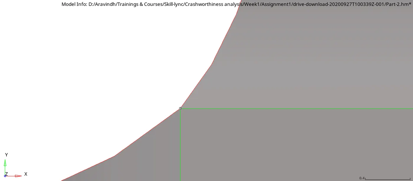
Fig 2.6: After replacing a point with another point
This procedure is repeated for all the 4 sides.
The same is the case for the edge points at the vertical sides of the model as shown in the following figure. The same operation is performed here, to correct the model.
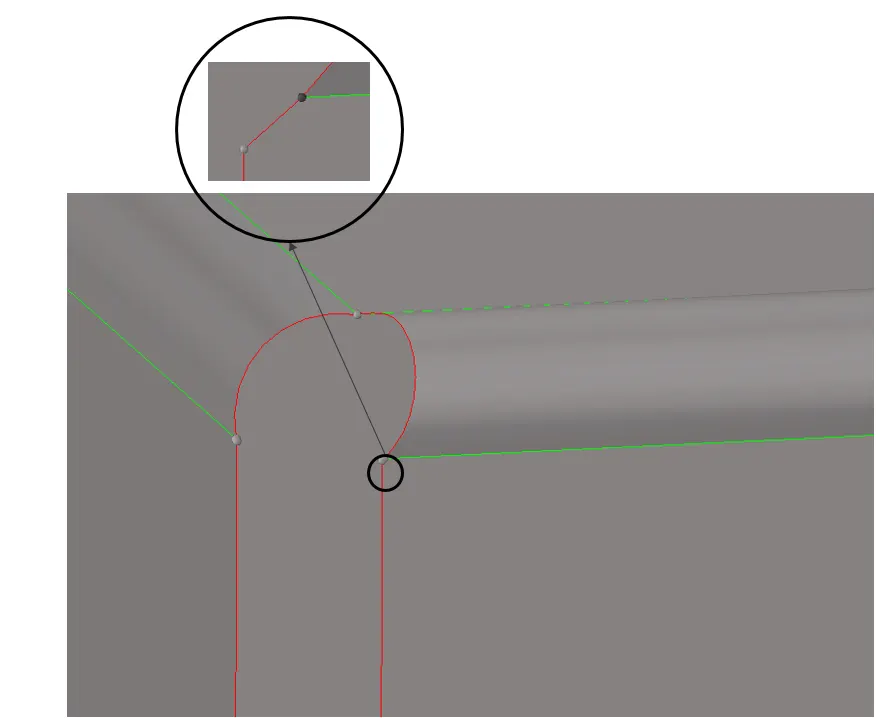
Fig 2.7: Edge points at the vertical sides
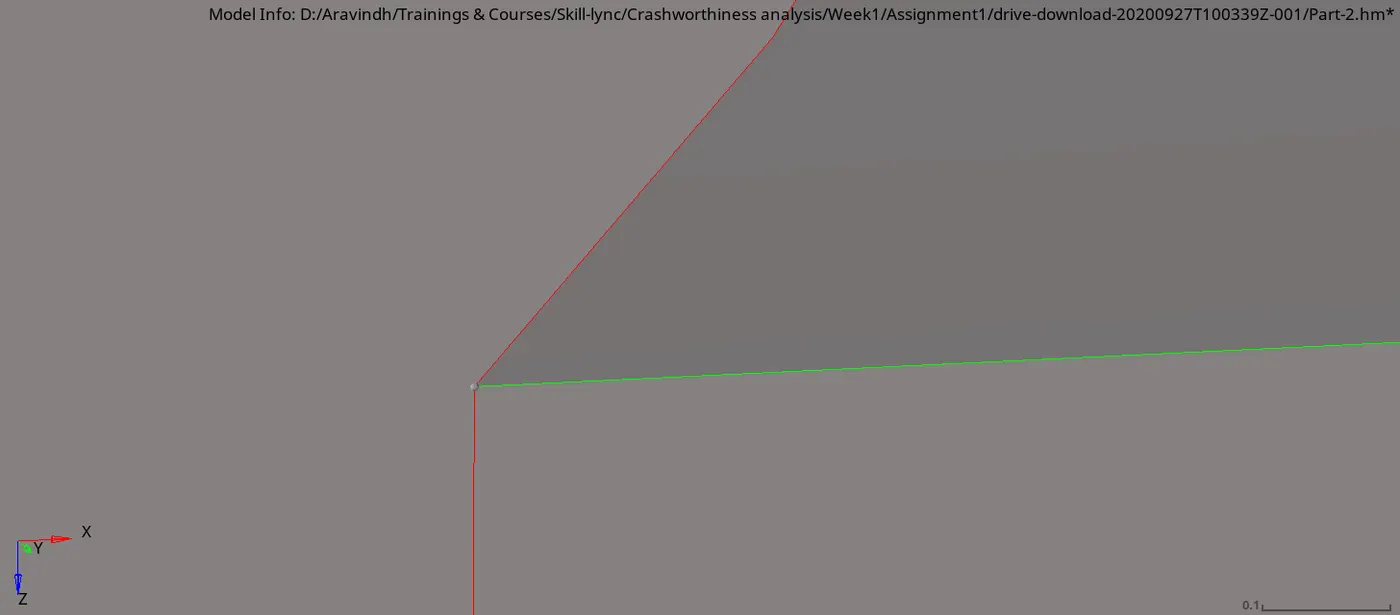
Fig 2.8: After replacing a point with another point
Meshing:
In order to have a better meshing on the top surface, “washer surface” option is used form quick edit menu. Washer surface creates a separate surface around the hole at the given offset distance. These washer surfaces can be then meshed separately, to get a better mesh around the hole and can have better mesh flow for the entire meshing of the top surface.
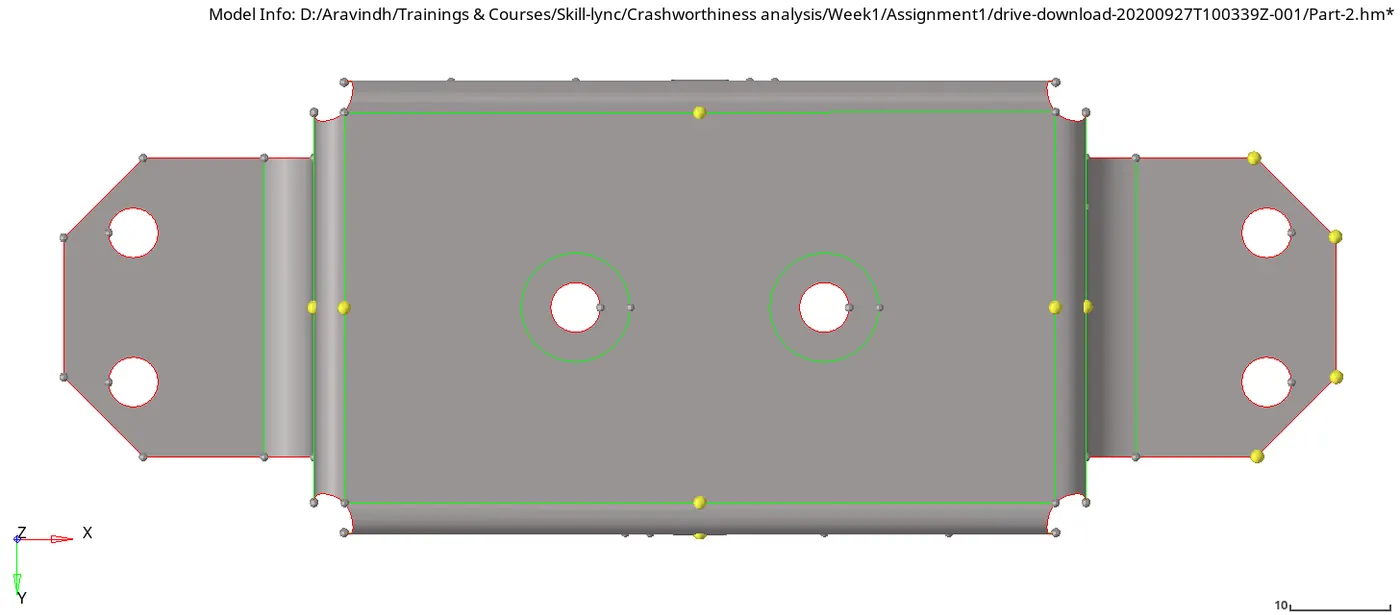
Fig 2.9: Washer surface
The washer surface is first meshed.
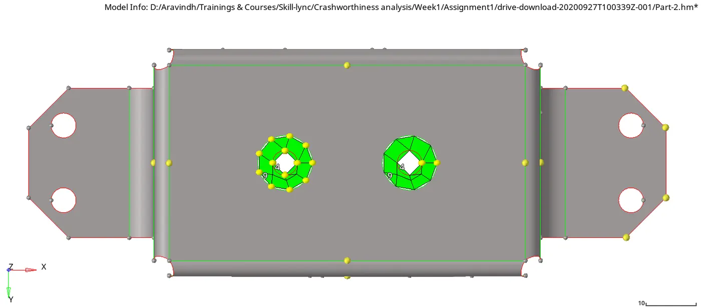
Fig 2.10: Washer surface initial mesh
Initially the mesh in the washer surface is not uniform, has lot of trias and the mesh flow is also bad. In order to have quad elements with the good mesh flow, the number of nodes on the inner and the outer edges of the washer surfaces are matched.
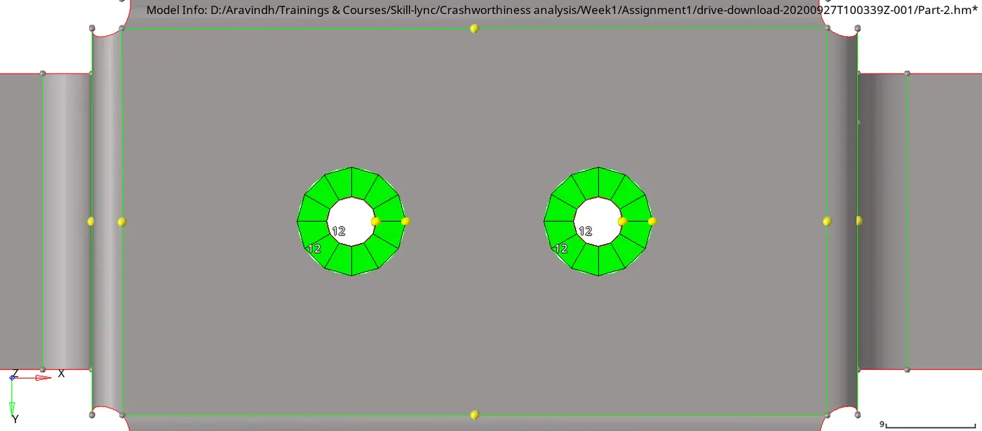
Fig 2.11: Washer surface after node match up
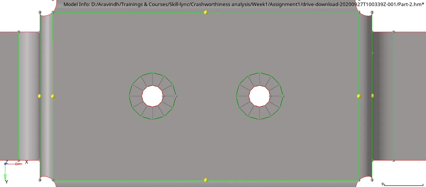
Fig 2.12: Washer surface mesh final
After the washer surface, the top surface around it is meshed.
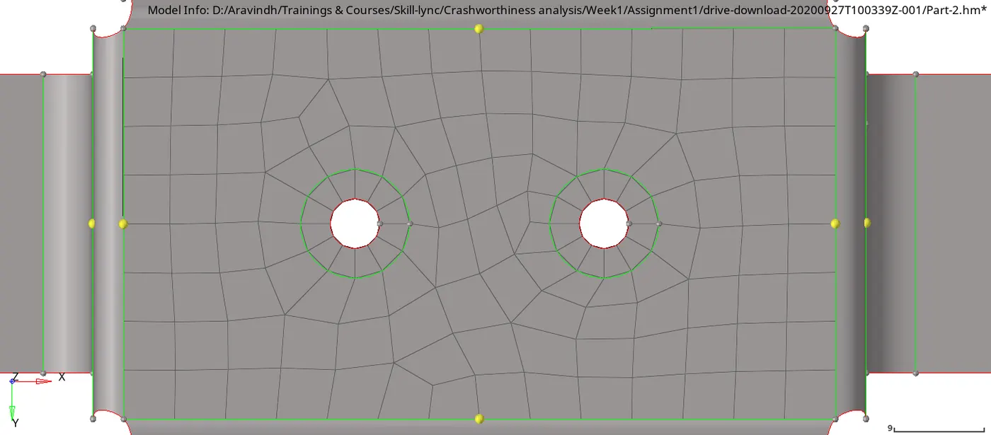
Fig 2.13: Initial mesh top surface
In order to remove few trias in the mesh and to have better mesh quality the mesh is refined and smooth option is used.
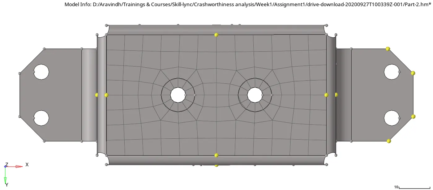
Fig 2.14: Final mesh top surface
The side faces of the model also has small holes of the same dimension as of above and there is also 2 other holes of higher dimension. So washer surface is used for these holes.
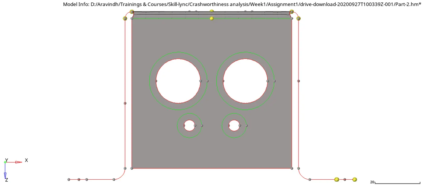
Fig 2.15: Creating the washer surface at vertical face
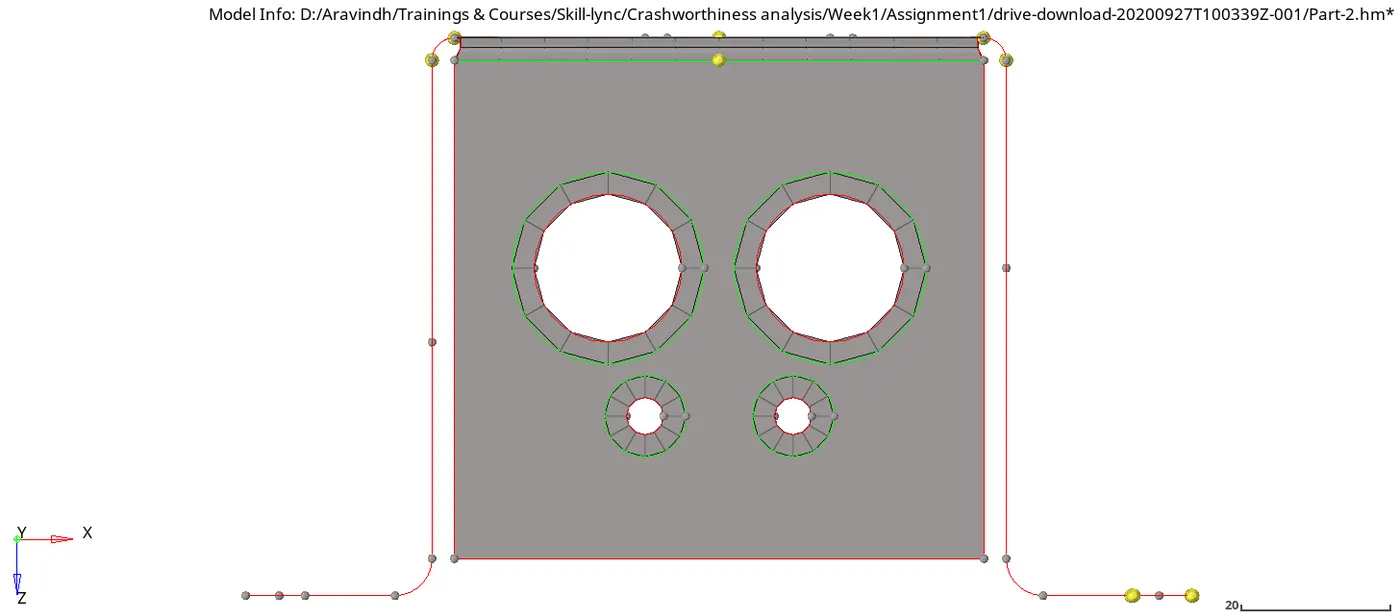
Fig 2.16: Washer surface at vertical face
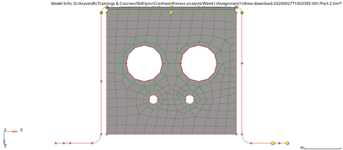
Fig 2.17: Mesh at one of the front vertical face of the component
For the small vertical side, washer surface is not used, since the circle is large with respect to the width of the face. So, the mesh can be generated with good quality even without the washer surface.
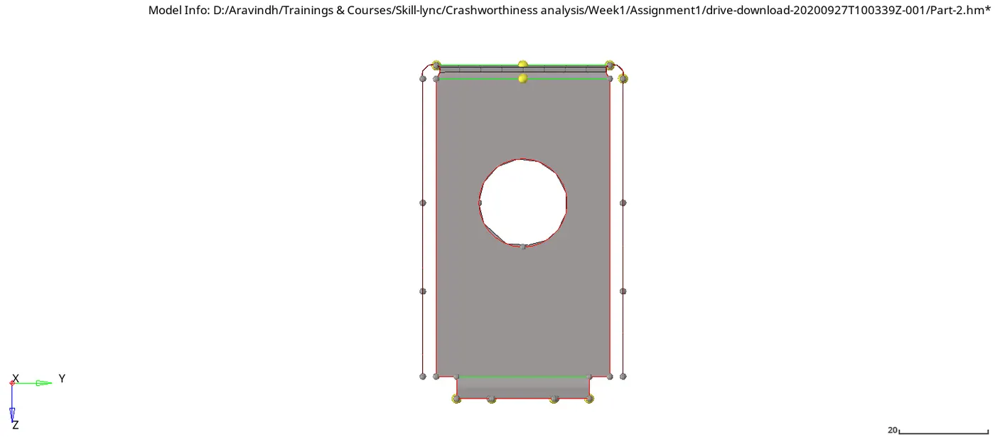
Fig 2.18: Side vertical face of the component
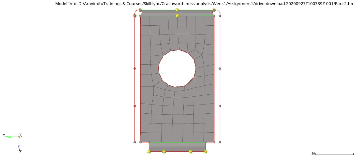
Fig 2.19: Mesh at one of the side vertical face of the component
For the bottom surface, there are two small holes near the chamfer of the face. Meshing without the usage of washer surface produces lot of trias and also mesh flow is not very good. The elements also failed few element quality criteria. So washer surface with the offset of 1 mm is used around the hole for better mesh quality.
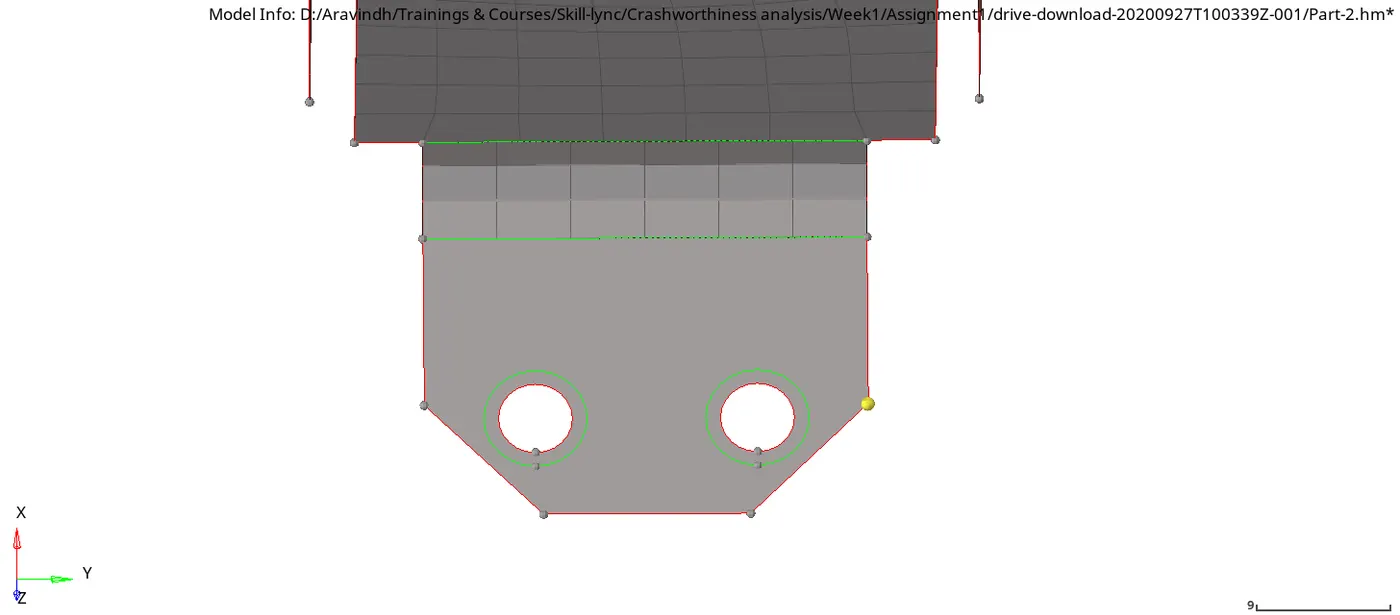
Fig 2.20: Bottom surface with washer surface
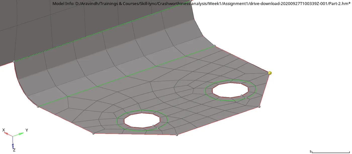
Fig 2.21 Mesh at bottom surface using washer surface
The vertical sides and the bottom surface are of same dimension to the corresponding surface on the opposite direction. Therefore the same mesh can be positioned to the other vertical face. The “position” option from the Tools menu is used to perform the mirror operation. The required elements are selected and the nodes on the top surface and on the fillet is chosen for the symmetrical plane, to reflect the mesh to the other face of the surface.
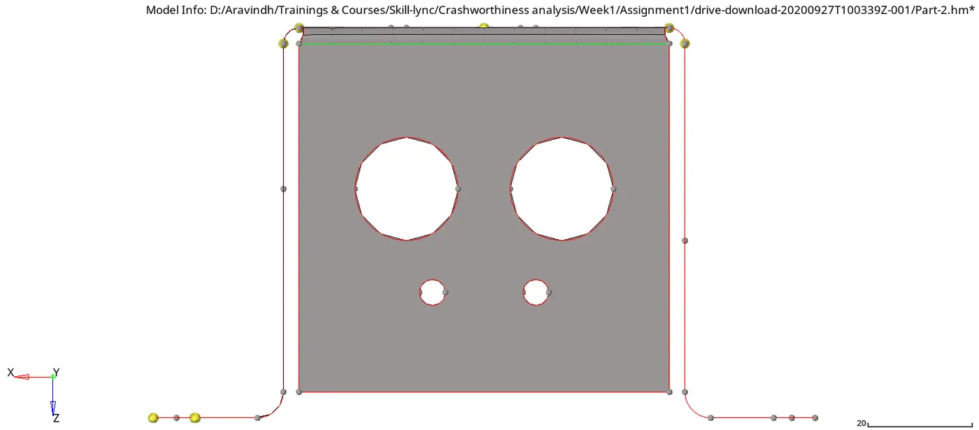
Fig 2.22: Back vertical face of the component before position
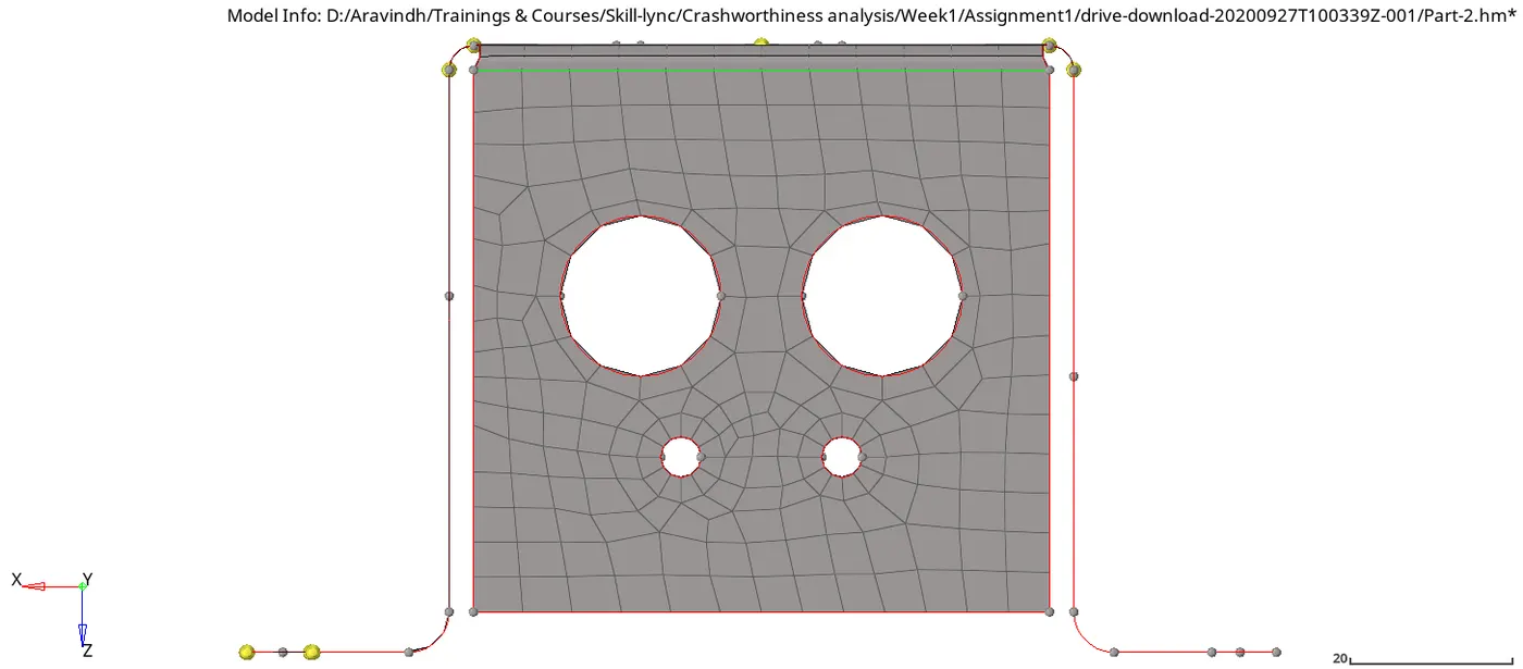
Fig 2.23: Back vertical face of the component after position
Fig 2.24: Side vertical face of the component before position
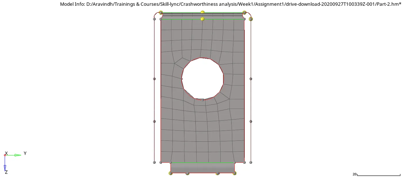
Fig 2.25: Side vertical face of the component after position
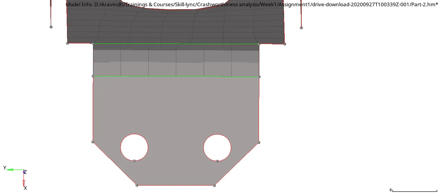
Fig 2.26: Bottom surface before position
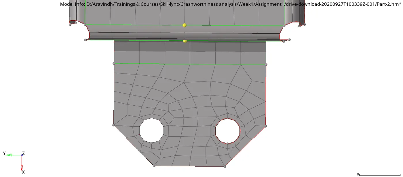
Fig 2.27: Bottom surface after position
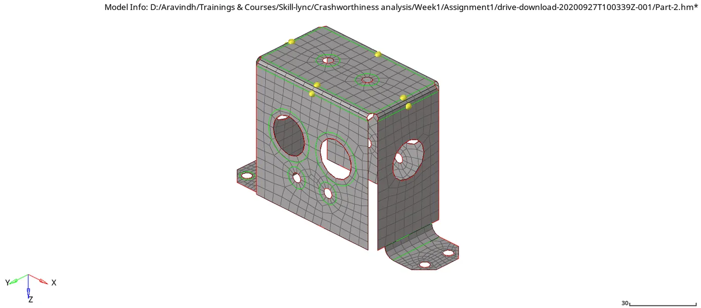
Fig 2.28: Final mesh
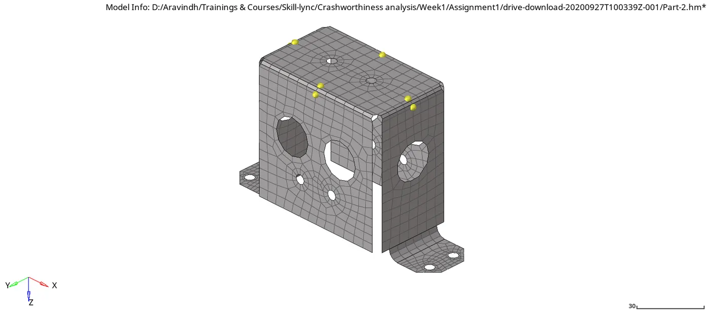
Fig 2.29: Final mesh without midsurface
Element Quality:
- Shell normal:
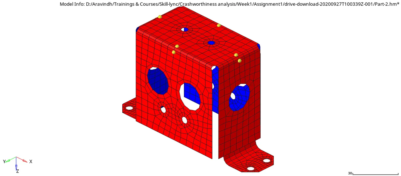
Fig 2.30: Surface normal of the elements
The surface normal of the shell elements are important. The normal of all the elements has to be in the same direction. Here, the normal of all the elements on the outer surface are pointed out.
- Duplicate elements:
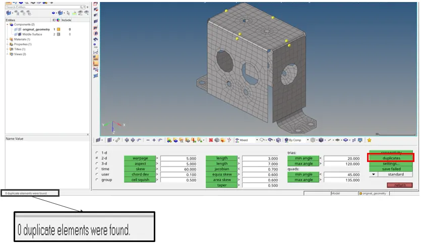
- Fig 2.31: Duplicate elements
- Element quality:
The quality of the element is checked, by specifying the target values such as maximum and mainimum element length, Jacobian, aspect ratio, Skew etc.
Fig 2.32: Quality criteria
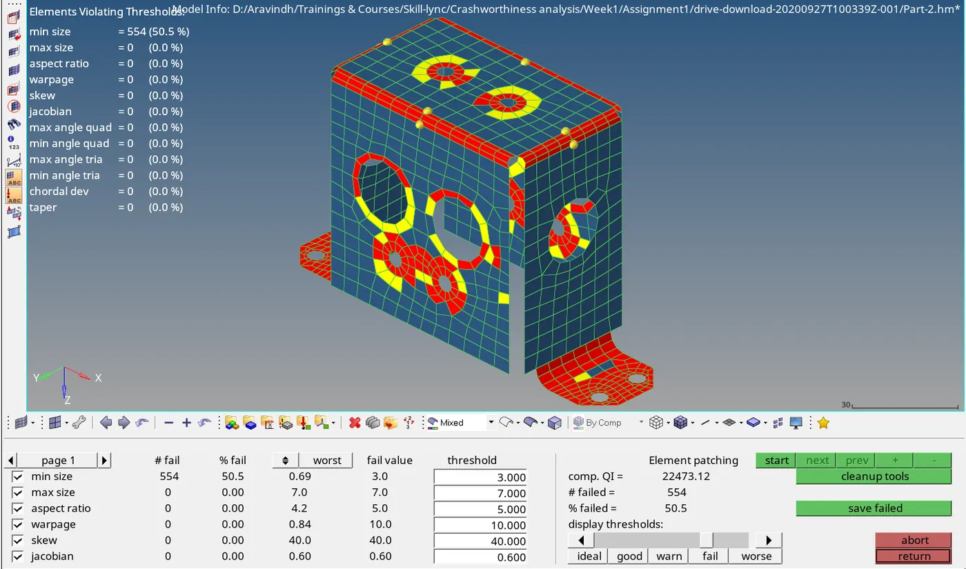
Fig 2.33: Quality criteria results
From the results, it can be seen that only minimum element length criteria cannot be met. Even these small elements are in washer surface, fillets, near chamfer, around holes and in thin sections around the holes. Small elements are needed in these sections to avoid high stress concentration, which may cause failure, and to have better mesh flow. So these can be ignored, because we get accurate result using smaller elements around these features with little to no change in simulation time.
Thickness:
A property is created for the midsurface using P1_SHELL card and thickness of 0.91 mm.
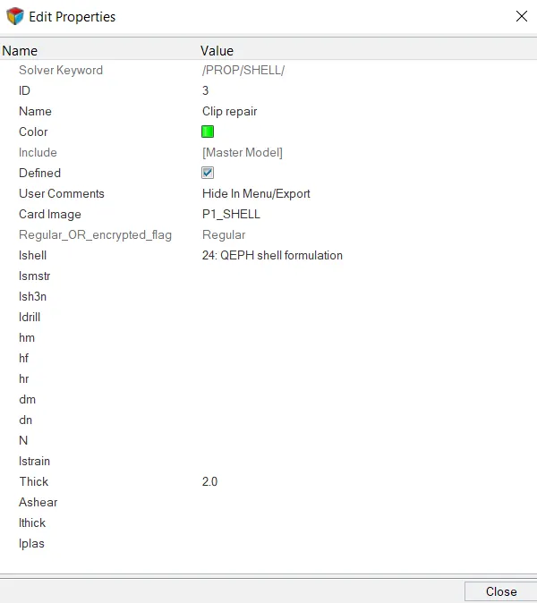
Fig 2.34: Property
Part 3 - Mounting Bracket:
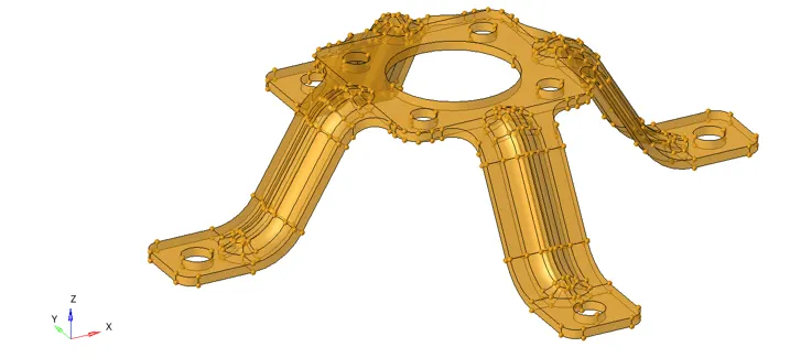
Fig 3.1: Component
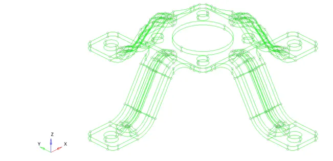
Fig 3.2: Model edges
There are no free edges in the component. So the midsurface can be extracted directly.
Midsurface:
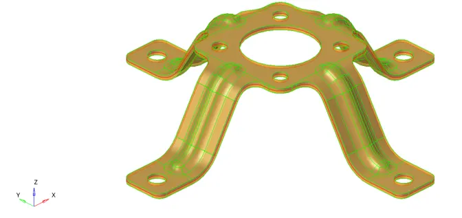
Fig 3.3: Midsurface with component surfaces
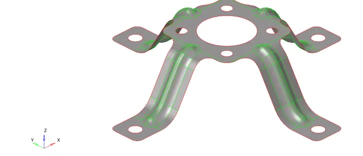
Fig 3.4: Midsurface
Cleaning Midsurface geometry:
In this component the diameter of all the holes are either 5 mm or above 5 mm, therefore all the holes are considered.
At the centre surface of the component, there is unnecessary edges around it. These edges creates a small separate surface near the fillet. When it is considered separately, it has to be meshed using fine elements, since it is curved surface and there is a fillet at its corner. Instead it can be combined with the centre component, which has some fraction of these fillets and therefore, it makes sense to mesh these surfaces together. To join the surfaces, “toggle” option is used to remove the edges.
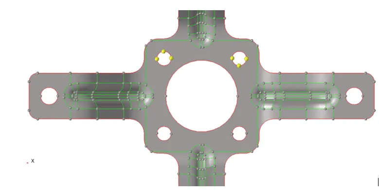
Fig 3.5: Centre surface with edges.
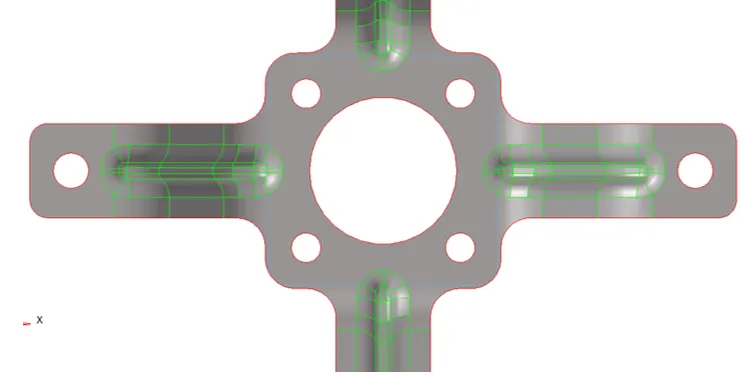
Fig 3.6: Centre surface after toggle
The component has 4 legs, which has consists of curved surfaces. These legs are split into multiple small surfaces, which represents the side of the curve. If the meshing is done on the surfaces separately, small meshes has to be used, which increases the number of elements and due to its small element length also increase the simulation time. Instead these surfaces can be combined together and element size can be chosen such that, the mesh maps the surface at highest accuracy.
“Toggle edge” option can be used to remove the unnecessary edges.
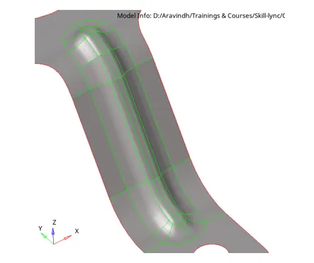
Fig 3.7: Surfaces at the center before toggling
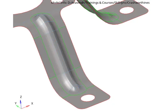
Fig 3.8: Surfaces at the center after toggling
This procedure is repeated for all the 4 legs. Now the model is ready for discretization.
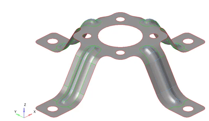
Fig 3.9: Cleaned Mid-surface
Meshing:
Since the top surface has 4 small holes, washer surface is first used around them and the created washer surfaces are meshed. If the washer surfaces are not used, the mesh flow is not good, because, it is a complex geometry, with lots of holes, fillets and curved surfaces. In order to improve the mesh quality, mesh flow and avoid sharp corners around the holes and adjacent fillets, washer surface option is used.
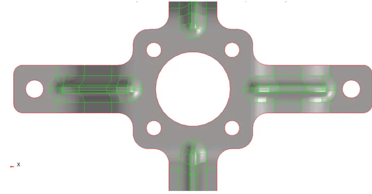
Fig 3.10: Before washer surfaces are created
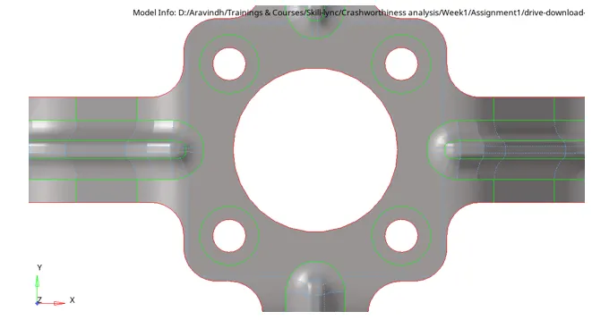
Fig 3.11: Washer surface
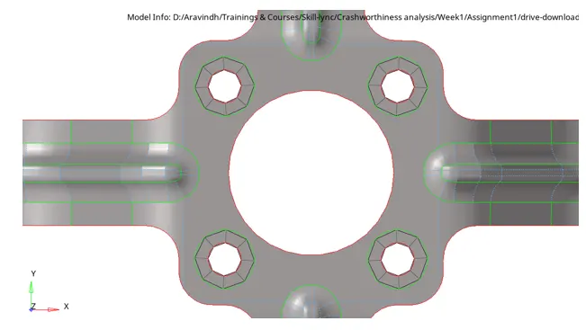
Fig 3.12: Meshed washer surface
Then the top surface is meshed. In order to capture the fillets and curved surfaces, the “node equivalence” option is used to match the node of the element with the temporary node created on the particular surface edges.
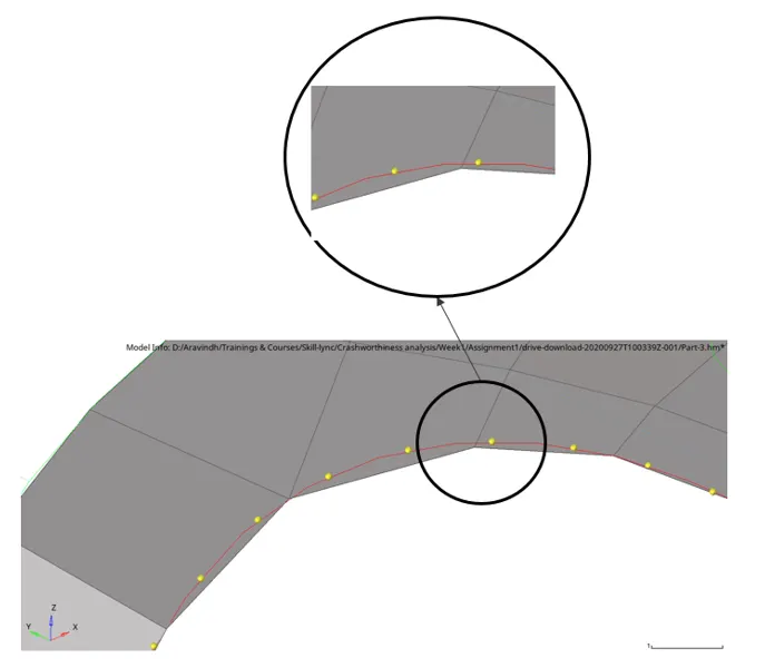
Fig 3.13: Before node equivalence
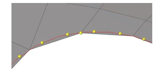
Fig 3.14: After node equivalence
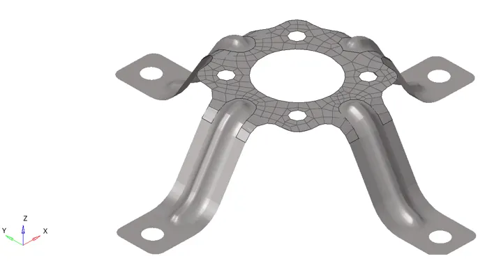
Fig 3.15: Final mesh at top surface
After the top surface, the legs are meshed.
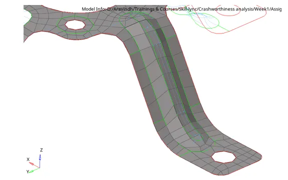
Fig 3.16: Final mesh at top surface
The same procedure is repeated for other legs of the model.
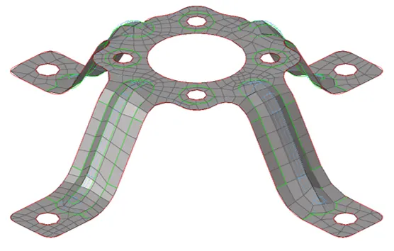
Fig 3.17: Final mesh with surface
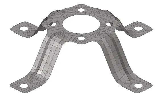
Fig 3.18: Final mesh without surface
Element Quality:
- Shell normal:
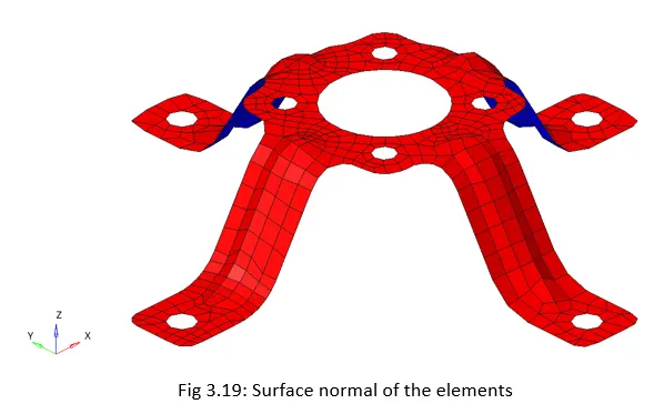
Fig 3.19: Surface normal of the elements
The surface normal of the shell elements are important. The normal of all the elements has to be in the same direction. Here, the normal of all the elements on the outer surface are pointed out.
- Duplicate elements:
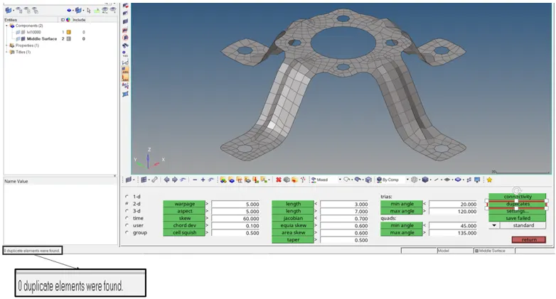
Fig 3.20: Duplicate elements
There are zero duplicate elements and there is no connectivity issues between the elements.
3. Element quality:The quality of the element is checked, by specifying the target values such as maximum and mainimum element length, Jacobian, aspect ratio, Skew etc.
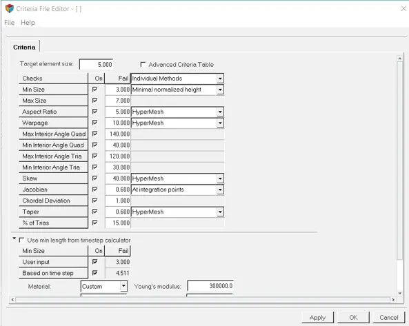
Fig 3.21: Quality criteria
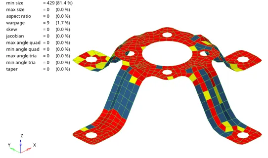
Fig 3.22: Quality criteria results
From the results, it can be seen that only the minimum element length criteria cannot be met at many areas. Since the geometry is complex with many holes, fillets, curved surfaces, surface fillets, small elements had to be used in these areas to get better mesh flow. Therefore the minimum element length cannot be met.
Thickness:
A property is created for the midsurface using P1_SHELL card and thickness of 0.91 mm.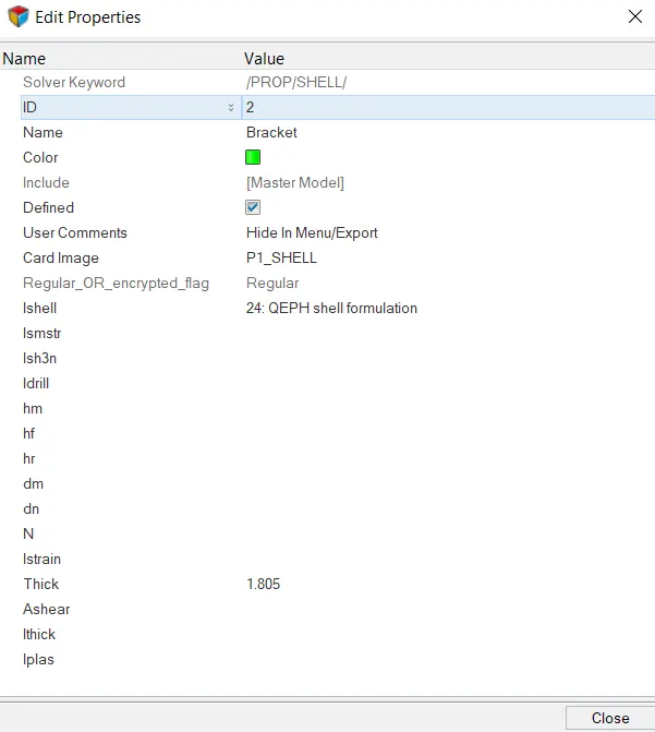
Fig 3.23: Property
Conclusion:
All the three components are preprocesses using HyperMesh and the report consist of the detailed description of the process undertaken fro the preprocessing.
The components are cleaned-up and meshed for the simulation with good mesh wuality and mesh flow. Even though, the minimum element lendth is not satisfied in certain sections of the geometries, it occur at the section with small features like fillets, holes etc., which has to be modelled accurately to avoid high stress concentration at the sharp corners, thereby preventing the failure of the component. Since tje components are small and only 2D shell mesh is used, the simulation time wont be changed a lot. Even though the simulation time might increase a little bit, accuracy of the results such as stress, deformation, energy, lifetime etc. will be much more accurate with this mesh.