Week 3 - 2D meshing for sheet metal
2D MESHING FOR SHEET METAL
AIM:
To Generate the mid surface for all the components after checking the geometrical errors and mesh the mid surface with the given element Quality criteria.
GIVEN:
QUALITY CRITERIA
|
S.No |
Quality Criteria |
Value |
|
1 |
Target/Average length |
5 |
|
2 |
Minimum Length |
2 |
|
3 |
Maximum Length |
7 |
|
4 |
Aspect |
3 |
|
5 |
Warpage |
15 |
|
6 |
Skewness |
45 |
|
7 |
Jacobian |
0.7 |
|
8 |
Minimum Quad Angle |
45 |
|
9 |
Maximum Quad Angle |
135 |
|
10 |
Minimum Tria Angle |
30 |
|
11 |
Maximum Tria Angle |
120 |
|
10 |
Tria Percentage |
15 |
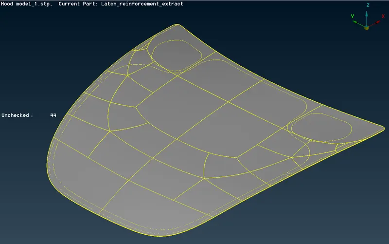
CAD MODEL:
PROCEDURE:
STEP 1:
Import the given model file_open_Hood model_1.stp
STEP 2:
Check the geometry by selecting Tools_checks_geometry and clear the error
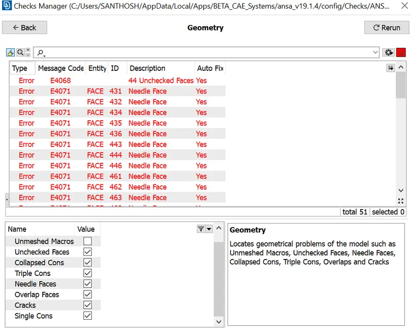
After checked and cleared the error by topocleanup, the component as been splitted into 5 model
To generate midsurface we have to find the thickness of the model
Go to Utilities_Measure and select the two points.
The splitted model and its thickness are shown below:
MODEL 1:
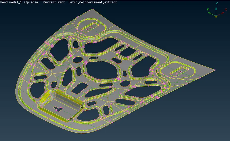
THICKNESS:- 0.75
MODEL 2:
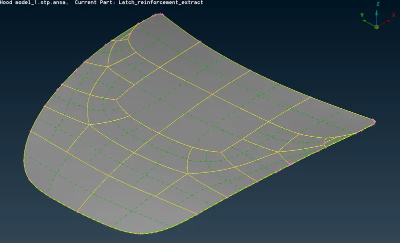
THICKNESS:- 0.75
MODEL 3:
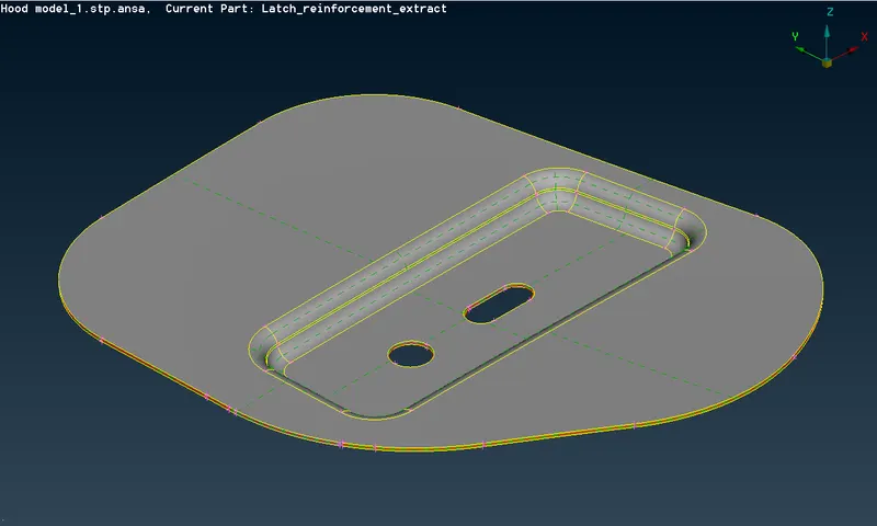
THICKNESS:- 1.2
MODEL 4:
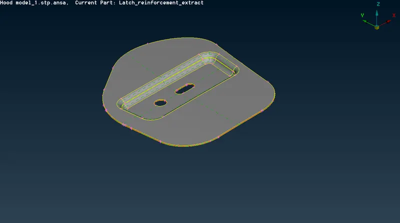
THICKNESS:- 1.2
MODEL 5:
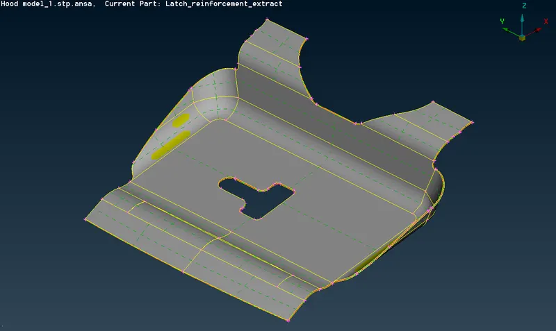
THICKNESS:- 1.2
MIDSURFACE:
For midsurface I choosed the manual method by offsetting the surface
Go to Modules buttons_Faces_Offset, select the one side face of the surface and enter the value of the thickness.
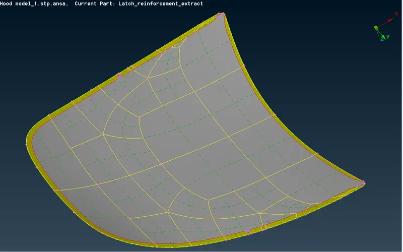
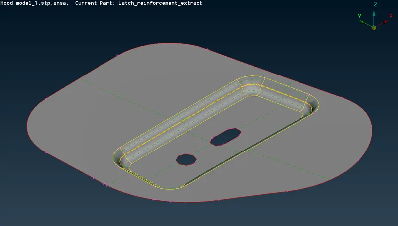
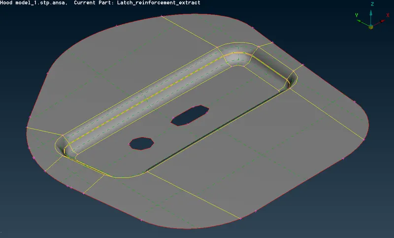
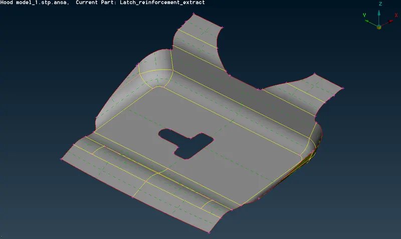
The final midsurface of each model are:
MIDSURFACE 1:
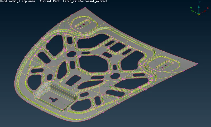
MIDSURFACE 2:
MIDSURFACE 3:
MIDSURFACE 4:
MIDSURFACE 5:
- Before mesh clean the geometry by topocleanup and cut option to get a better meshing
- Input the quality creteria value by pressing F11 and enter the given numbers.
- Enter the mesh parameter as per given target element length
- Go to modules_Mesh generations_Best and start meshing each surface
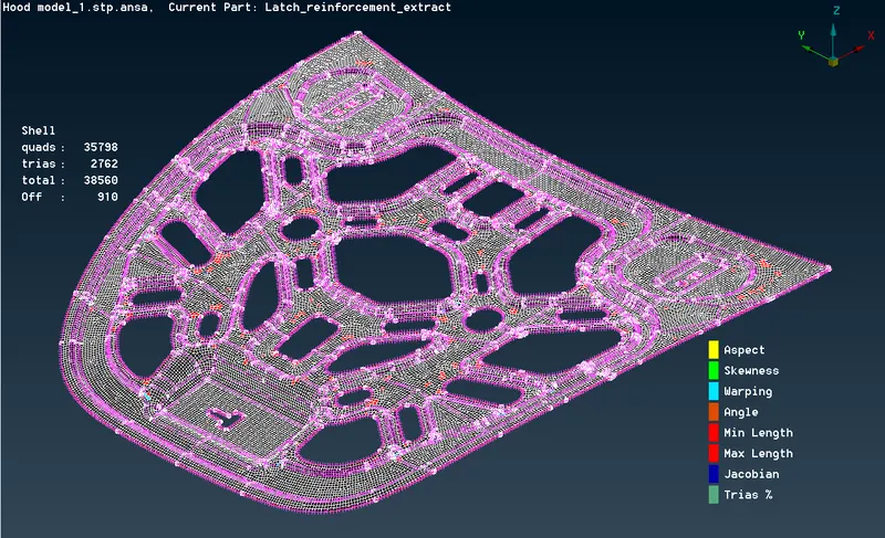
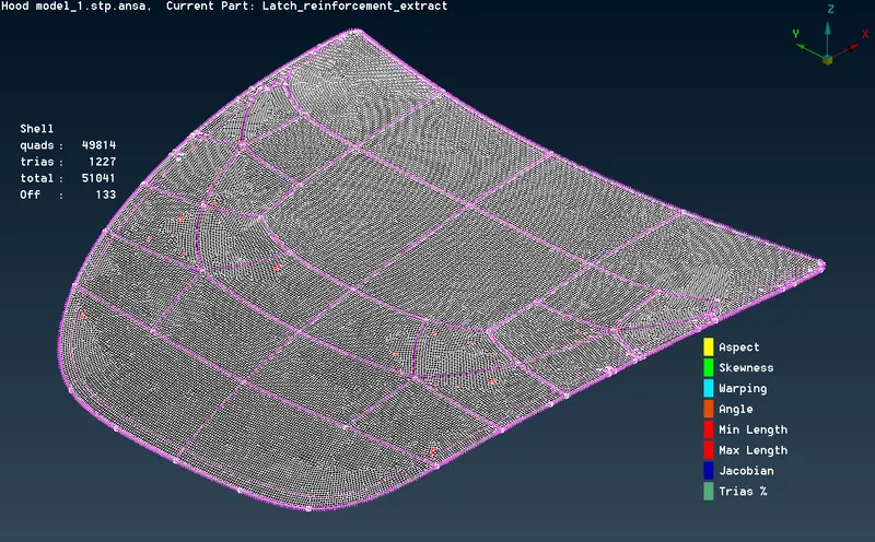
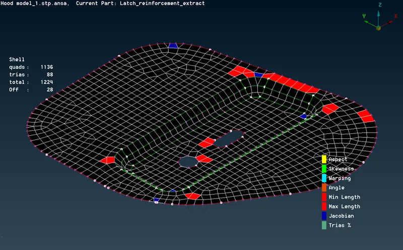
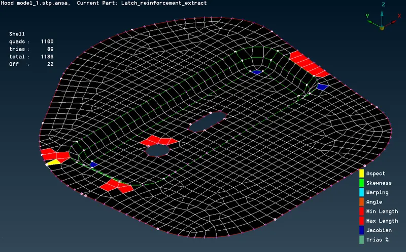
Meshed surface of each model and failure elements are shown below:
MESH SURFACE 1:
MESH SURFACE 2:
MESH SURFACE 3:
MESH SURFACE 4:
MESH SURFACE 5:
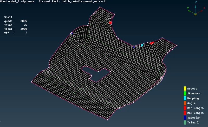
To clear the failure and to get proper mesh flow we can use the following methods:
- RECONSTRUCT on FEM.To apply this select Modules buttons_Shell mesh_Reconstruct
- SMOOTH on element.To apply this select Modules buttons_Shell mesh_smooth
- SPLIT AND SWAP on element.To apply this select Modules buttons_Elements_Split/Swap
- EDGE2PARAMETERS on macros.To apply this select Modules buttons_Macros_Edge2parameters
- Increase or decrease the node numbers.To apply this select Modules buttons_perimeters_Number/num+/-
COMPLETE MESH ON EACH MODEL:
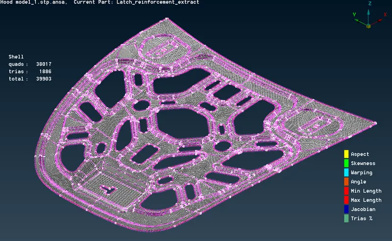
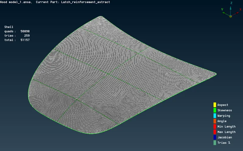
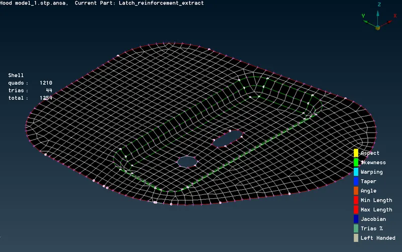
To check the elements are passed OFF elements should be zero with the quality creteria
MODEL 1:
MODEL 2:
MODEL 3:
MODEL 4:
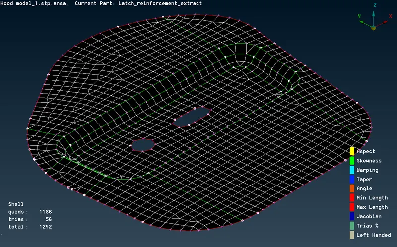
MODEL 5:
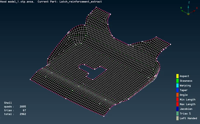
DRAW SHELL AS SOLID: After activating draw shell as solid the meshed shell elements will convert to solid,by considering the thickness assigned on PID
Go to Quality Creteria_presentation parameters_activate Draw shell as solid
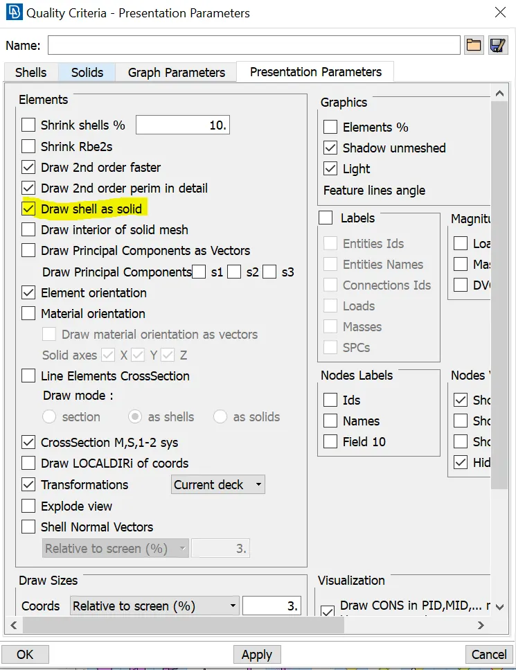
BEFORE SELECTING DRAW SHELL AS SOLID:
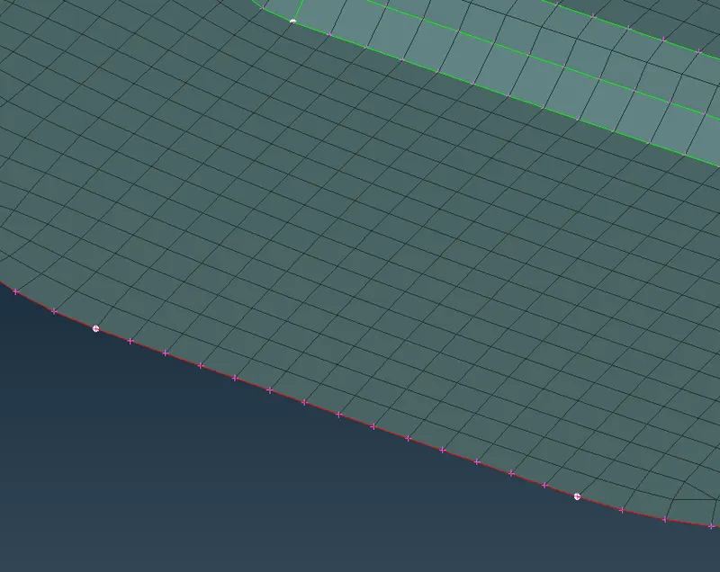
AFTER SELECTING DRAW SHELL AS SOLID:
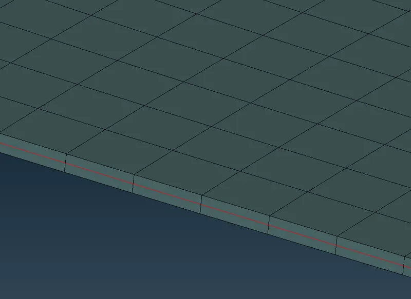
NOTE:Thickness has been updated on the element after activating draw shell as solid
LEARNING OUTCOMES:
At the end of this challenge I can able to:
- Perform geometry cleanup for any sheet metal component.
- Generate Midsurface manually without using automidsurface.
- Generate shell Mesh for any sheet metal component and knowledge of quality creteria.
- Identify quality failure and clear the failure and improve the mesh quality.
CONCLUSION:
Hence the geometrical error and mesh has been performed successfully.The thickness has to be generate after meshing.Quality failure are cleared and also got a proper mesh flow with low trias.