Week 3 - 2D meshing for sheet metal
Aim-
Take the mid surface for all the components of the given Hood model and mesh the mid surface with the given element Quality criteria.
Introduction-
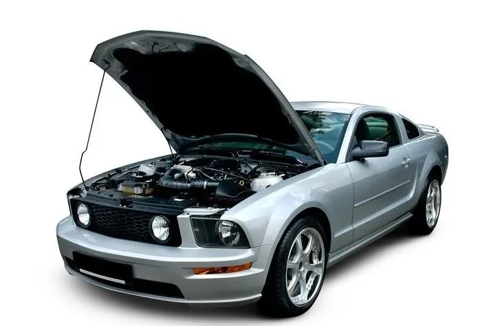
The hood or bonnet is the hinged cover over the engine of motor vechicles. Hoods can open to allow access to the engine compartment, or trunk for maintenance and repair. On front-engined cars, the hood may be hinged at either the front or the rear edge. A further variant combines the bonnet and wheelarches into one section and allows the entire front bodywork to tilt forwards around a pivot near the front of the vehicle.
Hoods are typically made out of the same material as the rest of the body work. This may include steel, aluminium, fiberglass or carbon fiber. However, some aftermarket companies produce replacements for steel hoods in fiberglass or carbon fiber to make the vehicle lighter.
ANSA file-
https://drive.google.com/file/d/1YH5NT6GcfbhSoVRGQIeQTqrGkI2FyZFS/view?usp=sharing
Given model-
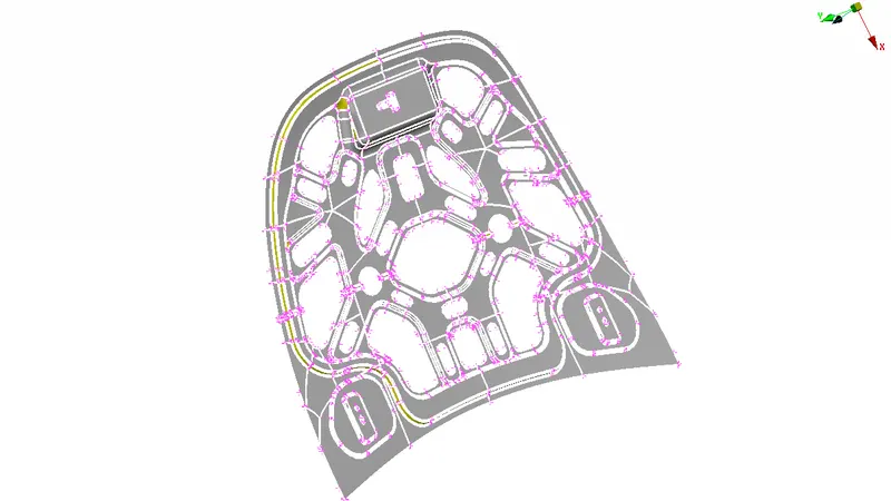
figure: Part1 (Inner Hood)
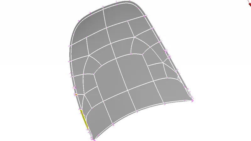
figure: Part2 (Outer Hood)
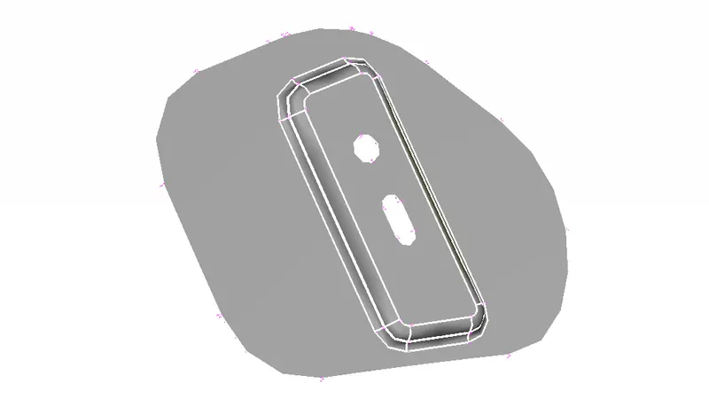
figure: Part3 (Hinge 1)
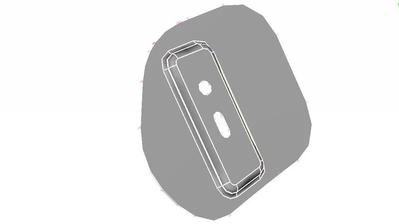
figure: Part4 (Hinge 2)
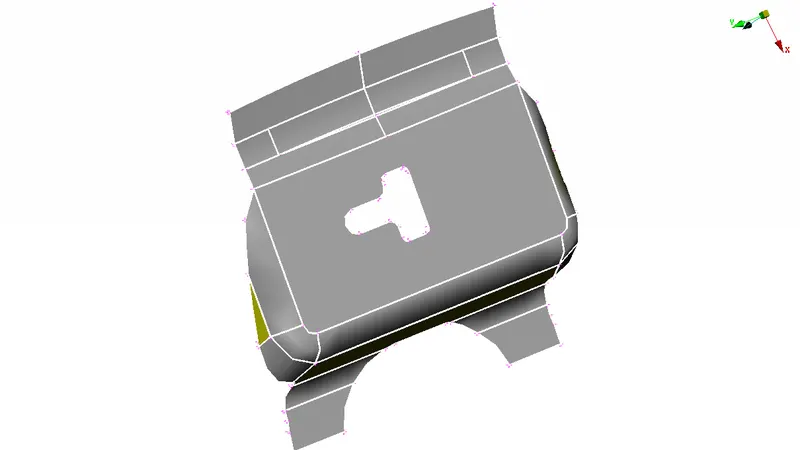
figure: Part5 (Latch)
Procedure-
Geometrical clean-up:
- Open each PID separately and measure the distance between any two cons in Utilities section. Since the distance is same throughout the model (=0.75mm), hence we can conclude that, it is sheet metal.
- In tool section, we go for checks geometry to checking the geometrical errors. After execute, select all and click on 'fix' option which automatically fixes the issues.
- To increase cons resolution, go to Topo module, select the Perimeters > Length then click the entire model using window selection (it basically defines the element length on selected perimeter segments). After that we see dialog box which has the value of length as 20 by default, change the value to 1 and click ok.
- Again check geometry to checking the geometrical errors.
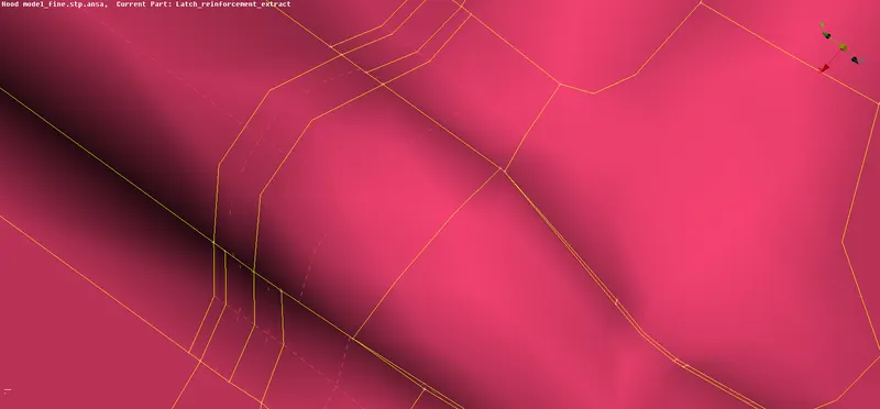
figure: without fine
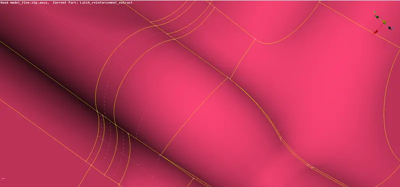
figure: with fine
Mid-surface generation:
- In Topo module, select Faces > Offset and change the selection model to Feature Area.
- Then select the cross hatches on one side of the model and give the angle value to 50 degrees, hence the neighboring surfaces that are above 50 degrees are not selected.
- On middle click confirmation, another dialog box pop-up and give the offset value to 0.75/2 and give the appropiate sign.
- Then using !Not option to select only mid surface.
- Select Faces > Set PID and select the entire surface using window selection. Right click then New > PSHELL and change the name to mid-surface01, give the thinkness value 0.75 and change the PID to 1.
Shell Meshing:
- In Utilities, go to Mesh Parameters and give the target length, minimum target length and maximum target length 5 mm, 2 mm and 7 mm respectively.
- Go to Mesh module then click Perimeter > Length > Perimeter and select the whole model and give the value 5 mm.
- Now we need to cross-check of the entire model if there is element having less or more than given values.
- We use defeaturing in many cases, suppose there are 2 cons present in middle of the model and both are represnting the same features and also the distance between them is much small, then we delete any one of them using Macros > Join.
- For any kind of holes present, make the alignment parallel to the near by boundary using Perimeter > Slide.
- Check the total number of nodes present in the hole using Perimeters > Number > select the hole's perimeter . And if it is odd then we add or delete one node to make it even and this can be done using Perimeters > Num +/-.
- F11 to open the quality criteria and give all the above values then apply.
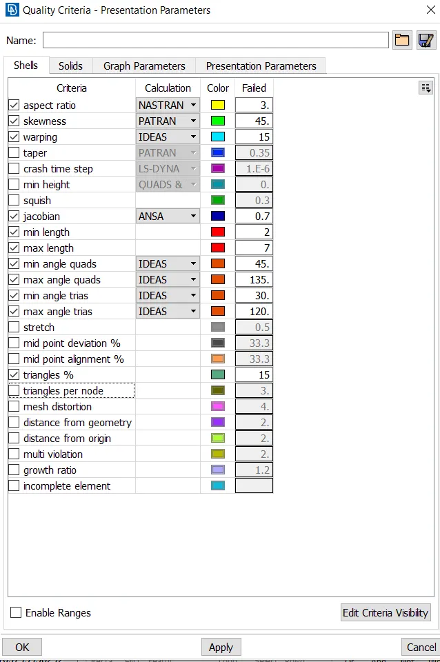
- Type of mesh is general, element type is mixed (quad and tria), order of element is 1st order.
- Select Mesh Generation > Best and select the entire model and click ok.
- Switch on Hidden mode in Auxilaries to see how many elements are falling under mentioned criteria.
- Using Reconstruct option to make elements good.
- If still any element fails then go to manually to that area. If tia is present at boundary then using Macros > Cut and Elements > Swap to fix this issue.
- The click on entire model then Smooth option to get better mesh flow in model.
Mesh results-
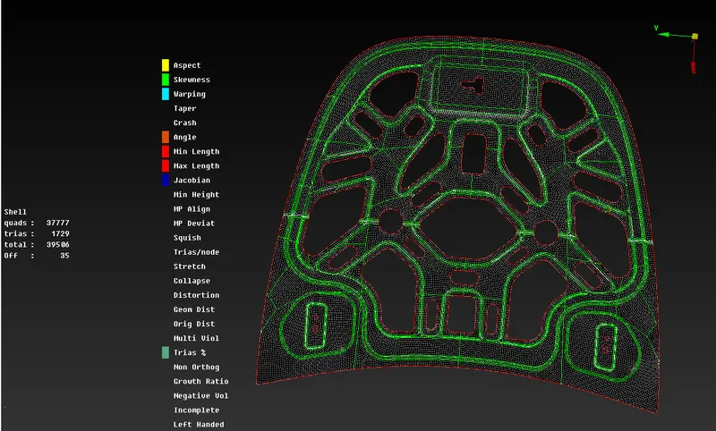
figure: mid surface of part 1
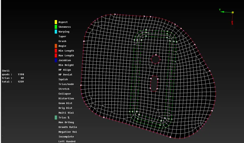
figure: mid surface of part 3
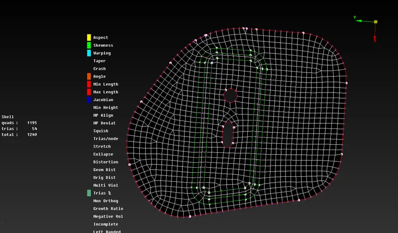
figure: mid surface of part 4
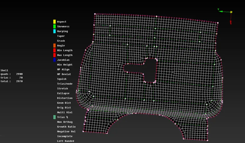
figure: mid surface of part 5
Learning Outcomes-
- Initially I was using Fine option for increasing cons resolution but it takes so much time and also it does not increase it uniformly. But after using Length option, it is easy and more accurate.
- In mesh generation, it was showing one surface is unmeshed. So when I clicked on it and give And commnad, no neighbour found which means it has no thinkness. So I deleted that surface since it will not affect my CAD geometry and results.
Conclusion-
- Mid surface extraction and meshing are done successfully but I accidentally changes some geometry of second part due to which I was unable to extract mid surface of that part which is very easy to be done.