Internal Geneva Mechanism
Objective-
- Use the following 2D CAD drawings to create the 3D model of the internal Geneva mechanism (driver and driven wheels)
- Perform motion analysis by rotating the driver wheel at 10 rpm and 20 rpm.
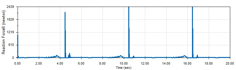
- To plot the Contact force (between driving and the driven wheel) as a function of time for both cases..
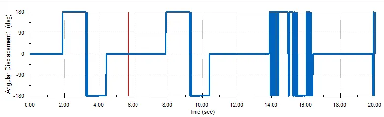
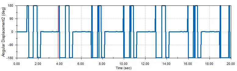
- To plot the Angular Displacement of the driven wheel for both cases.
- Compare the contact forces with and without "Precise contact".
Given 2D CAD drawing-
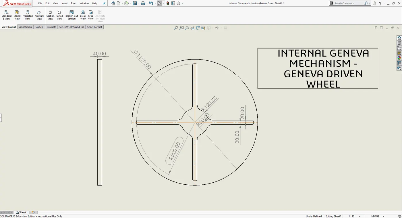
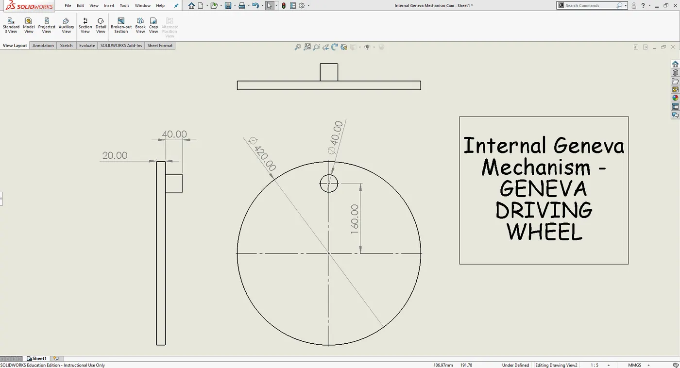
Theory-
Geneva drive-
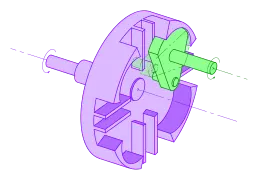
The Geneva drive is a gear mechanism that translates a continuous rotation movement into intermittent rotary motion.
The rotating drive wheel is usually equipped with a pin that reaches into a slot located in the other wheel (driven wheel) that advances it by one step at a time. The drive wheel also has an elevated circular blocking disc that "locks" the rotating driven wheel in position between steps.
Internal version-
An internal Geneva drive is a variant on the design. The axis of the drive wheel of the internal drive can have a bearing only on one side. The angle by which the drive wheel has to rotate to effect one step rotation of the driven wheel is always smaller than 180° in an external Geneva drive and always greater than 180° in an internal one, where the switch time is therefore greater than the time the driven wheel stands still.
3D model-
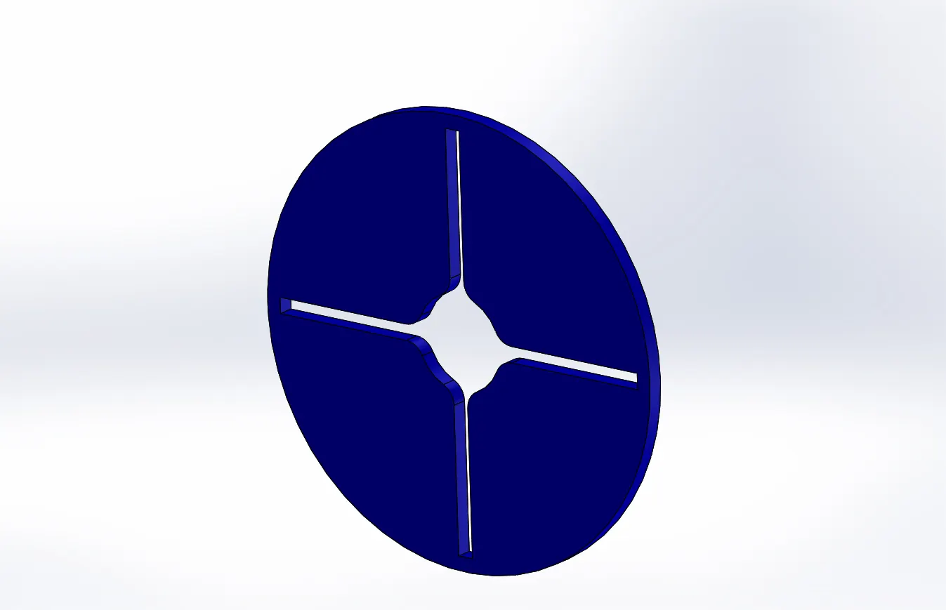
- Make 3D CAD model using 2D CAD drawing with proper specification.
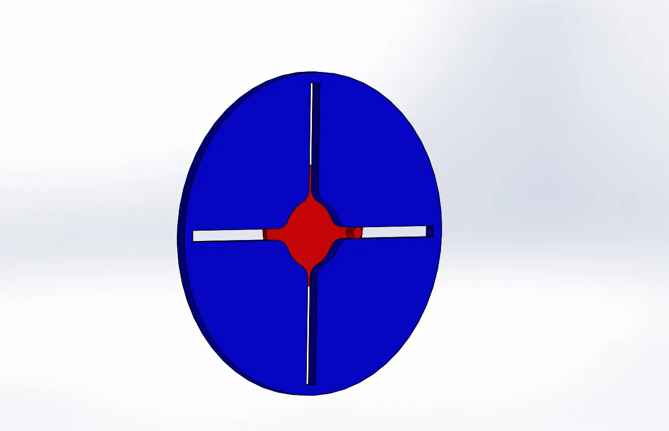
Driven wheel-
Driving wheel-
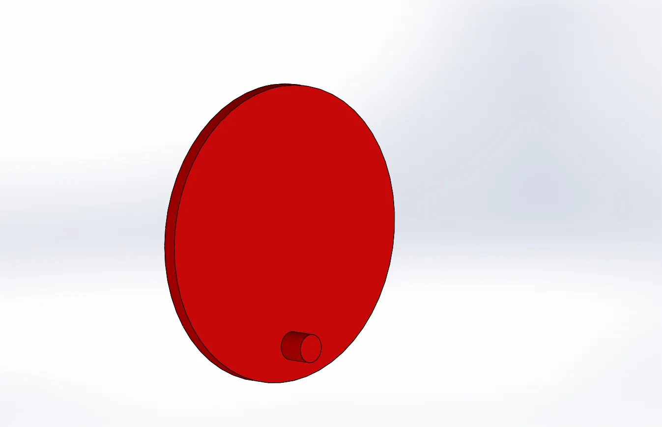
Assembly-
- Choose top plane of assembly drawing and mate it to the lower face of driving wheel and make them coincident.
- Select top plane and sketch, select lower edge of driving wheel and go for convert entities. And select this sketch and mate it to round face of driving wheel and make them concentric so that it can rotate at fixed center.
- Select lower face of driven wheel and upper face of driving wheel and mate it with some distance.
- Now placed the driven wheel manually at the right place so that pin is not touching the inner side of the slot of driven wheel.
- Select top plane and sketch, select lower edge of driven wheel and go for convert entities. And select this sketch and mate it to round face of driven wheel and make them concentric so that it can rotate at fixed center.
Motion analysis-
- Go to Solidworks motion in Solidworks Add-Ins.
- Select motion analysis.
- Go to setting and select 60 frames per second and 120 frames per second for 10 rpm case and 20 rpm case respectively.
- Select on Use Precise Contact and unselect it for obtaing different results as per the question. Use different motion study at each time.
- Select contact and select solid body and select driven and driving wheels. And also select the body 'dry steel' for both driven and driving wheels.
- Select motor and fix it to the center of driving wheel.
- Make it run for 20 sec.
Results-
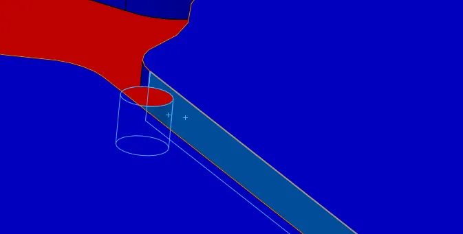
Precise contact selection-
- Select pin of driving wheel and slot of driven wheel.
For 10 rpm-
contact force-
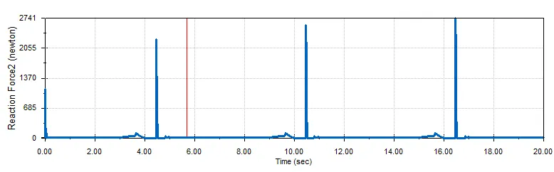
contact force without precise contact-
Angular Displacement of the driven wheel-
For 20 rpm-
contact force-
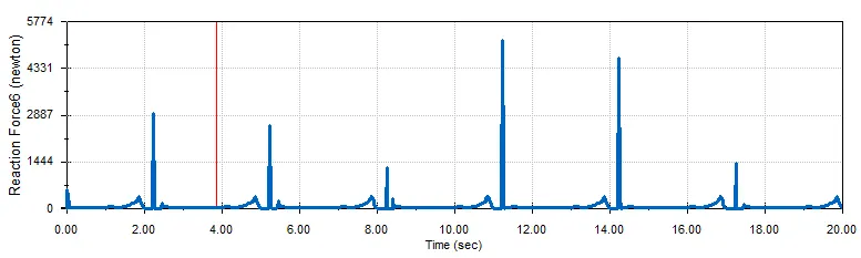
contact force without precise contact-
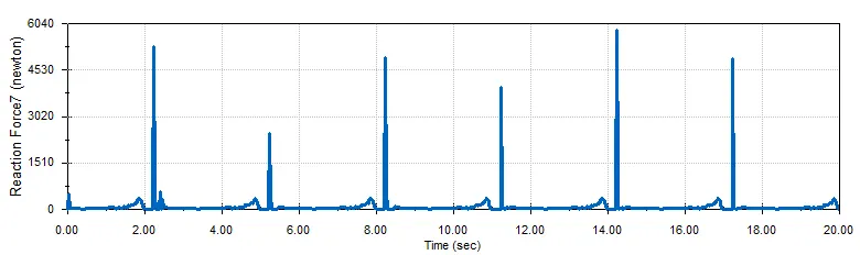
Angular Displacement of the driven wheel-
Conclusion-
- The precise contact gives more accurate result.
- When driven part tries to enter in the slot of driven wheel, it faces sudden jerk as per the plot.
- When we increases the rpm, it faces more jerk as per comparison between both cases.
- Angular displacement graphs shows that the displacement occurs between -180 to 180 degree.