Week - 4 - 2D meshing for Plastic components
https://drive.google.com/file/d/1N8GzajST0XEdPhckwjtWUPR9Tdl4obiA/view?usp=sharing
ANSA file:
https://drive.google.com/file/d/1N8GzajST0XEdPhckwjtWUPR9Tdl4obiA/view?usp=sharing
Aim-
For the given Plastic Bottle Cap model, check for the geometrical errors and take the mid surface by suitable mid surfacing techniques. PID and Thickness assignment has to be done for all the mid surfaces. Mesh the same with given element Quality criteria.
Procedure-
Geometrical clean-up:
- Open model and measure the distance between any two cons in Utilities section. Since the distance is vary throughout the model, hence we can conclude that, it is plastic model.
- In tool section, we go for checks geometry to checking the geometrical errors. After execute, select all and click on 'fix' option which automatically fixes the issues.
Mid-surface generation:
- Using Offset and middle command, mid surface of basic parts are done.
Taking mid surface of complicated part:
- We are taking mid surface of highlighted part shown in the figure. Select first face and give the offset value and similarly do for second face seperately (both faces are shown).
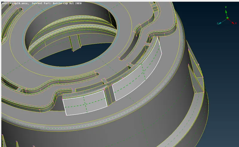
fig 1: Faces > Offset
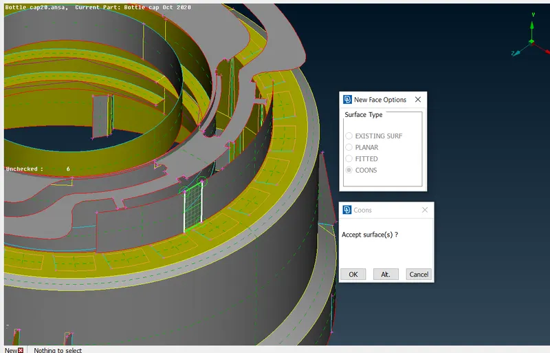
fig 2 : Then using Faces > New ; to create a surface between these two surfaces.
To take mid surface for Teeth:
- Middle option (in Curves) is used to create a middle curve at the front face of the tooth.
- Use CONS > Project and select the line from the back side and Project that line to Base mid surface.
- Select both the curves and create a surface, which is mid surface of a tooth.
- Repeat same process for all tooth.
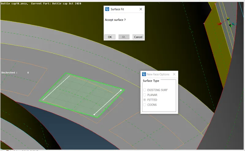
fig: Surface type: Fitted
To take mid surface for Threads:
- Curves > Middle is used to create a curve at the middle of the selected two cons (shown in below figure).
- Fine option is used multiple times over purple colour curves to increase resolution of the curve. By doing this, a curve will come on the top surface of the threads.
- The middle curve is then projected in Normal direction to the base mid surface.
- Pick double cons and the middle curve and create a new surface, which is mid surface of the thread.
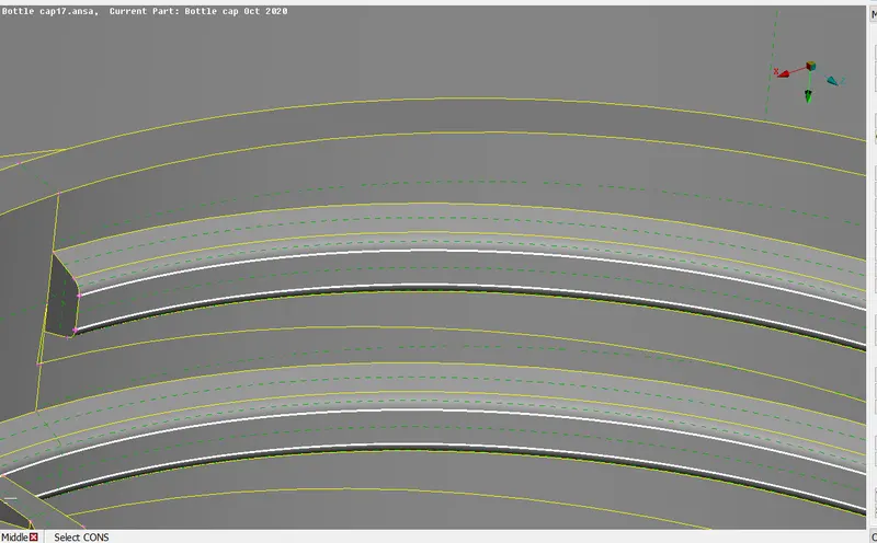
fig: selecting CONS
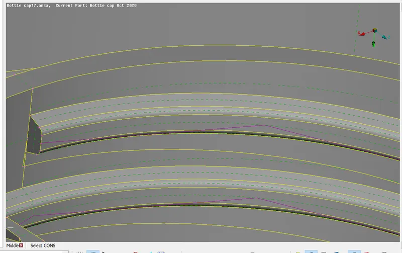
fig: before fine
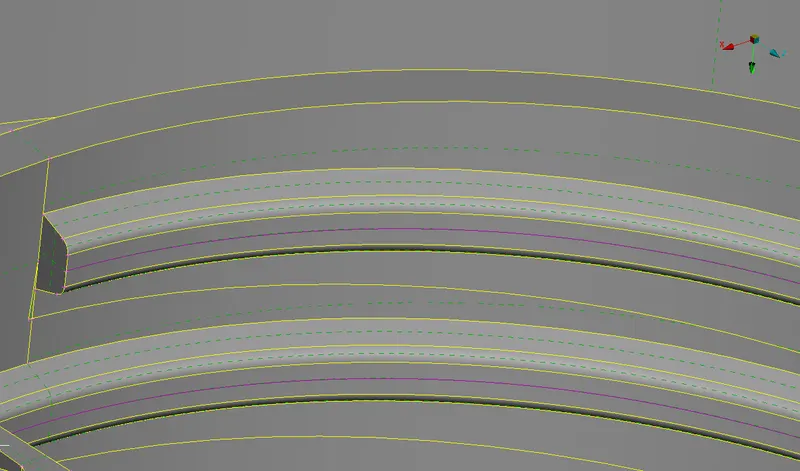
fig: after fine
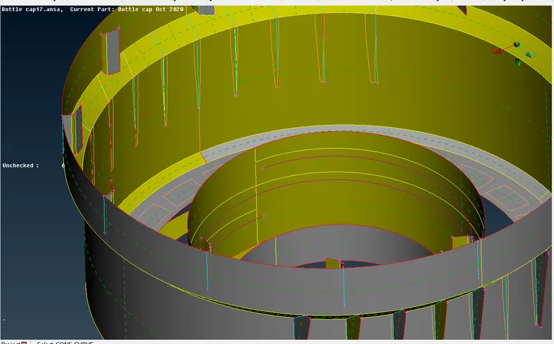
fig: CONS project
Shell Meshing:
- In Utilities, go to Mesh Parameters and give the target length, minimum target length and maximum target length 1 mm, 0.5mm and 3 mm respectively.
- Now we need to cross-check of the entire model if there is element having less or more than given values.
- We use defeaturing in many cases, suppose there are 2 cons present in middle of the model and both are represnting the same features and also the distance between them is much small, then we delete any one of them using Macros > Join.
- F11 to open the quality criteria and give all the above values then apply.
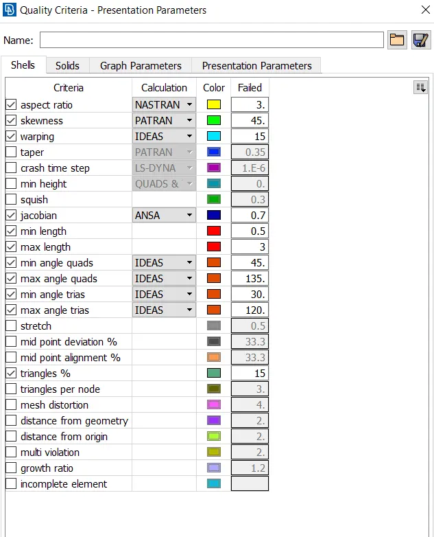
- Type of mesh is general, element type is mixed (quad and tria), order of element is 1st order.
- Select Mesh Generation > Best and select the entire model and click ok.
- Switch on Hidden mode in Auxilaries to see how many elements are falling under mentioned criteria.
- Using Reconstruct option to make elements good.
- The click on entire model then Smooth option to get better mesh flow in model.
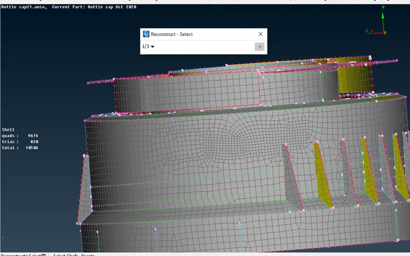
fig: before reconstruct
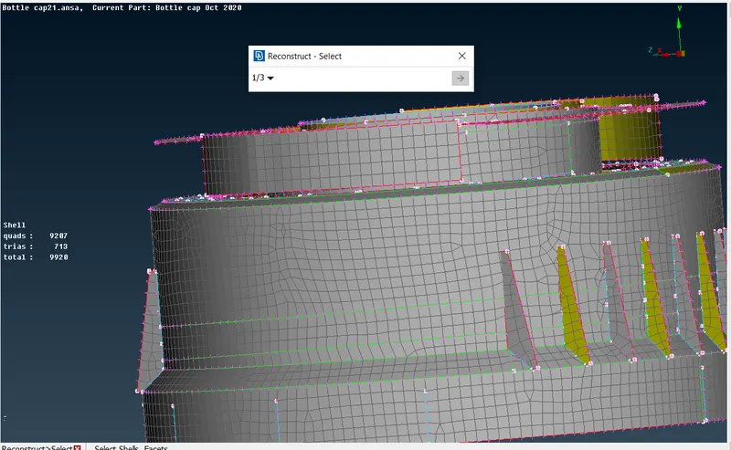
fig: after reconstruct
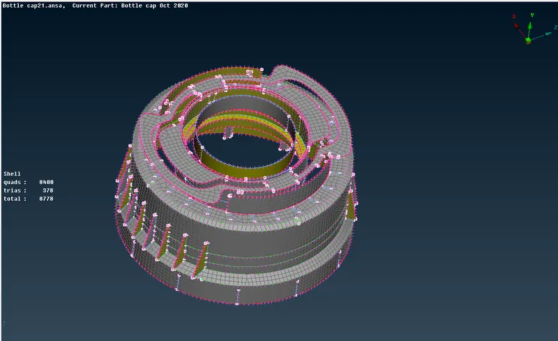
Mesh results-
Learning Outcomes-
- I learned that how to take the mid surface of the complicated areas using Faces > Middle > Multi and other commands.
- In mesh generation, it was showing one surface is unmeshed. So when I clicked on it and give And commnad, no neighbour found which means it has no thinkness. So I deleted that surface since it will not affect my CAD geometry and results.
Conclusion-
- Mid surface extraction and meshing of given model is done successfully.