Week 3 - 2D meshing for sheet metal
AIM:
In given model,take the midsurface then proper mesh flow with good element quality criteria and then assign thickness of the midsurface
OBJECTIVE:
- Take the midsurface of given model
- Take 2D meshing with proper mesh flow
- Element quality criteria should pass.
- Thickness must be assigned to midsurface
PROCEDURE:
STEP 1:
Given model.
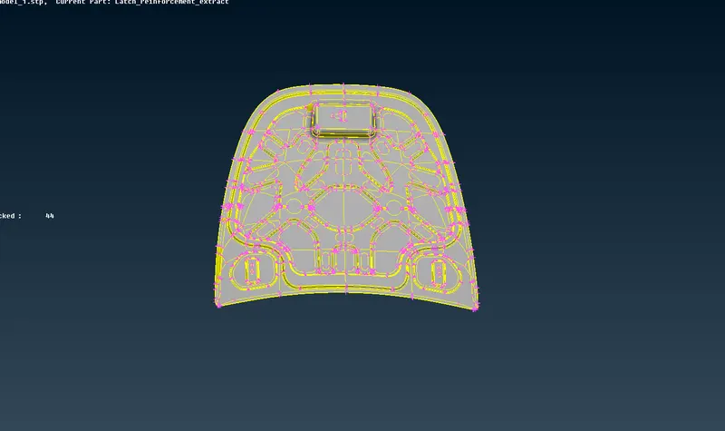
STEP 2:
Each component have different property
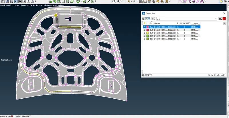
As same for other component
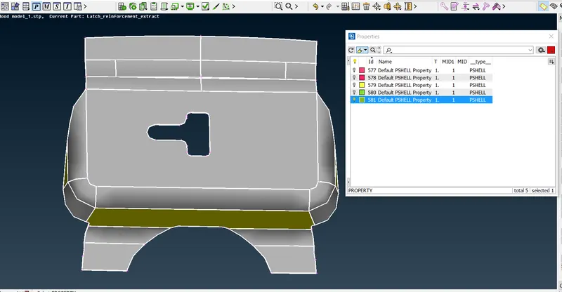
STEP 3:
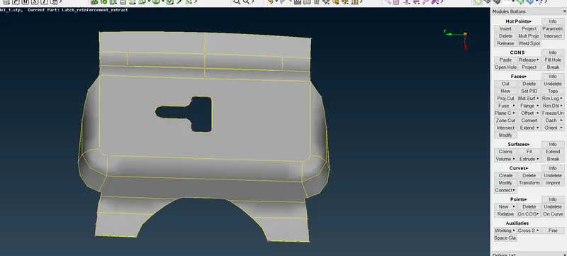
Do orient of this component.
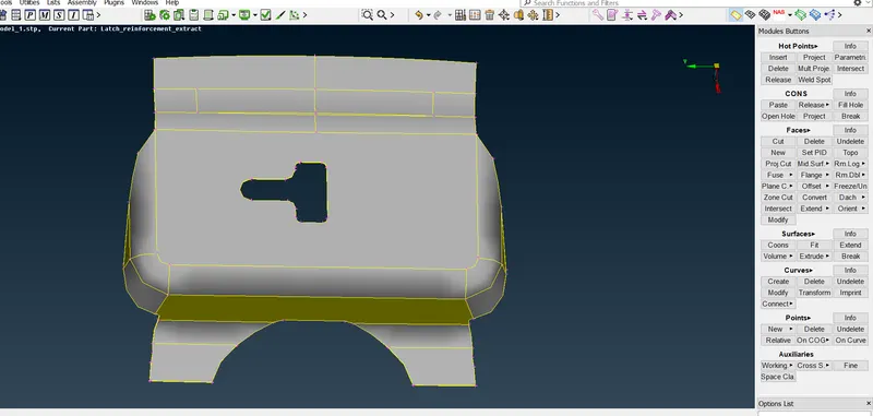
Go to faces----orient----it extract
STEP 4:
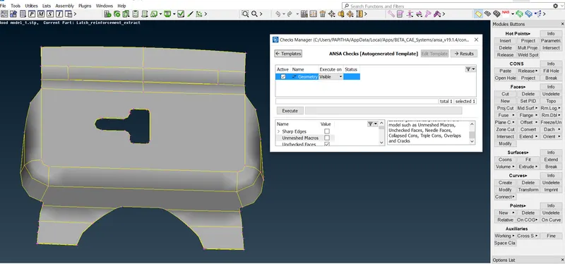
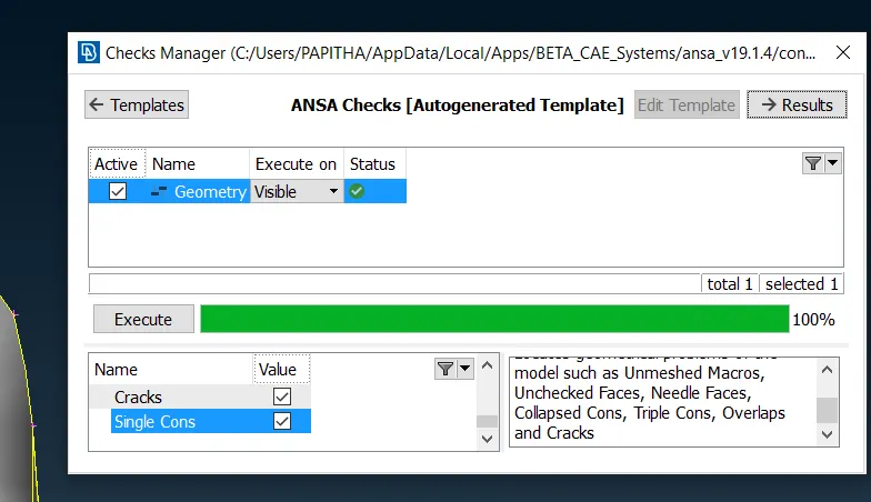
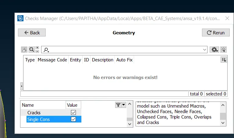
Now, do check geometry.
Go to check manager----geomtery----excruete----click result
STEP 5:
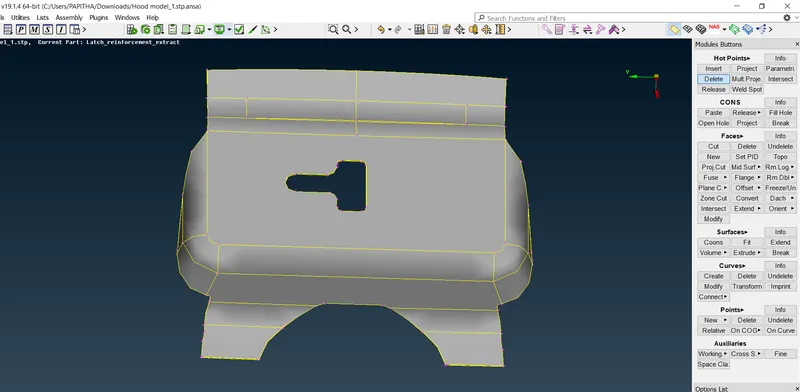
Delete the unwanted points that is hot points.
Go to hotpoints----delete-----select all.
STEP 6:
Extract midsurface of given model.
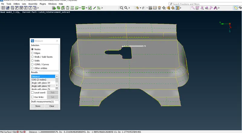
* Measure distance to take midsurface
Go to measure----modes----distance----asssign it.
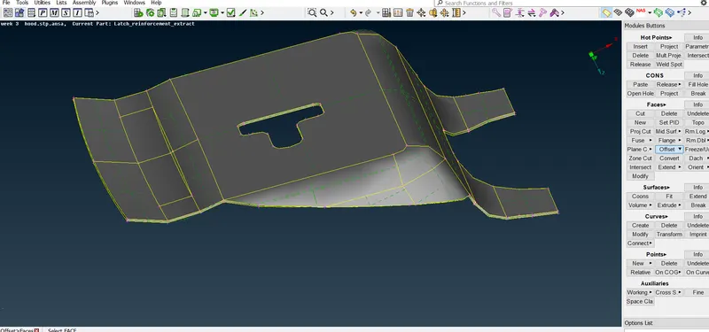
Go to faces--- offset----iNot----PID region---click feature line---
STEP 7:
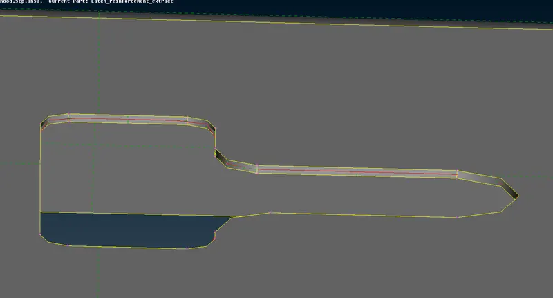
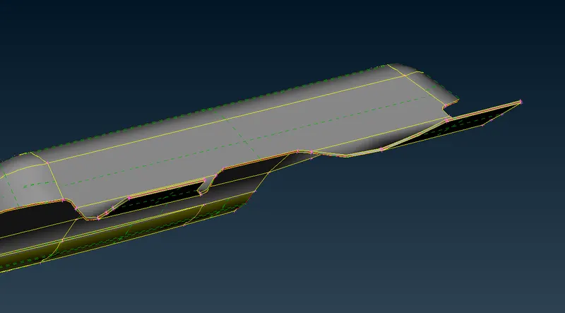
Select the 1faces----click middle mouse button---put offset value.
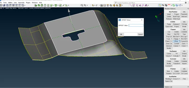
Midsurafce has extracted.
STEP 8:
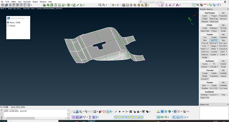
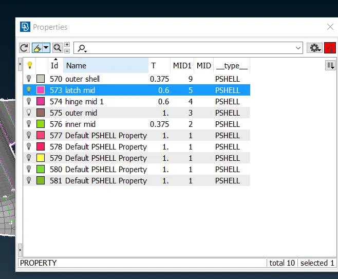
Latch mid surface extract place in seperate property.
STEP 9:
Go to 2D mesh----perimeter----length----select all perimeter given value as 5---then xtract.
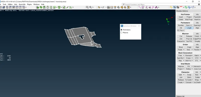
Same for macros

STEP 10:
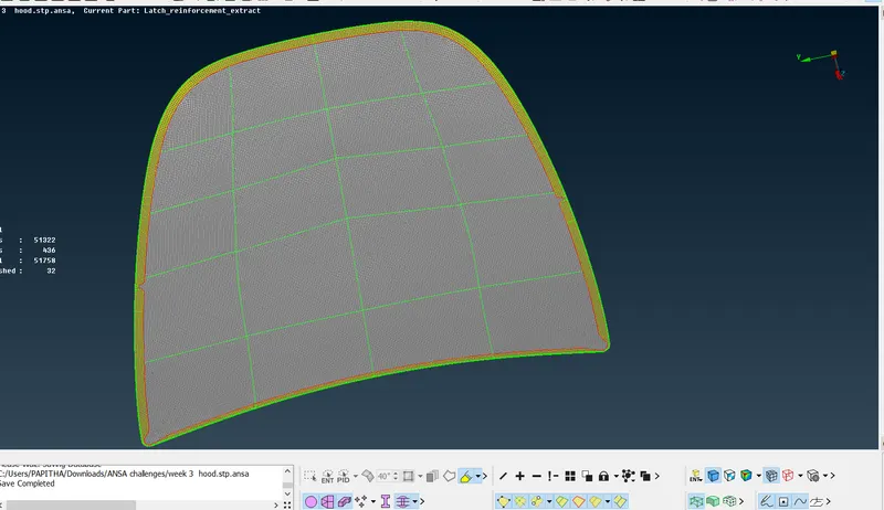
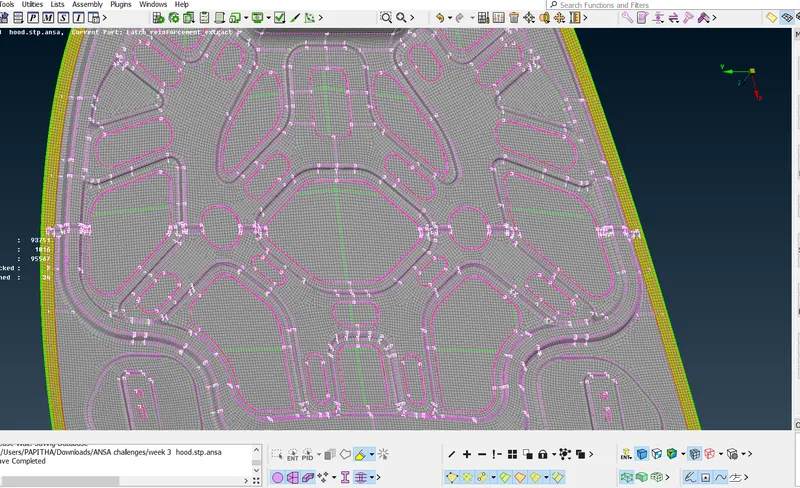
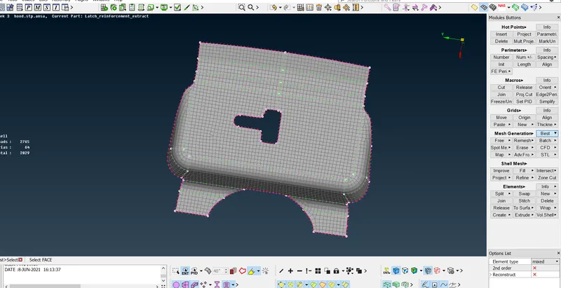
Now, do 2D meshing.
Go to 2D meshing----mesh generation---best----select all ---extract it.
STEP 11:
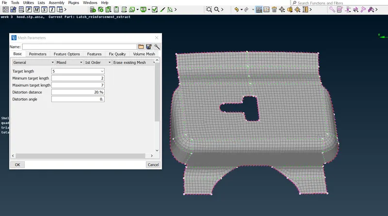
Then go to mesh parameter----apply the given values.
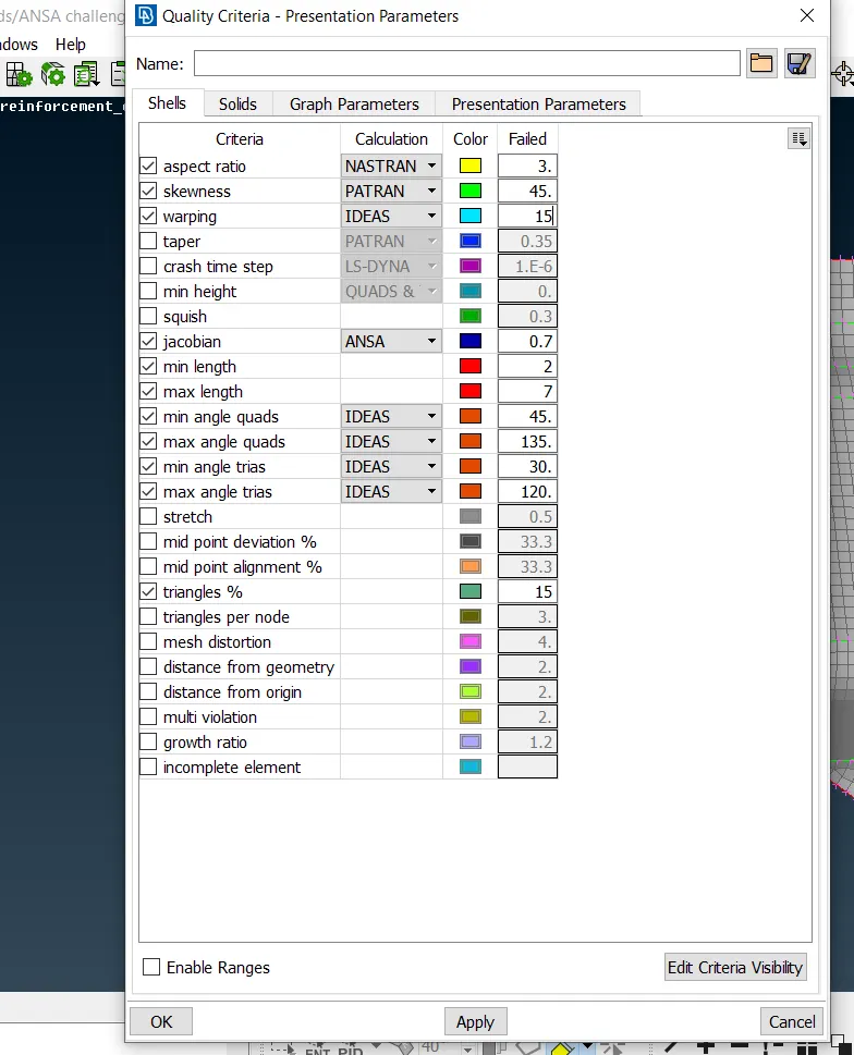
Then, apply the values in quality criteria...
STEP 12:
Now, go to hidden box---to check the quality criteria
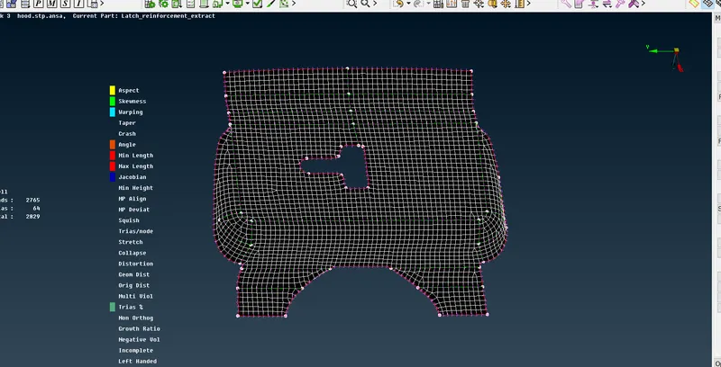
STEP 13:
As same for other component.----midsurface of outer panel
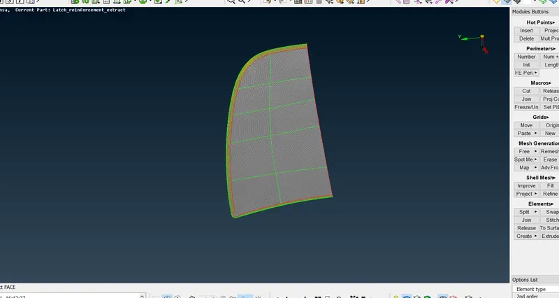
Check the quality criteria of the model.
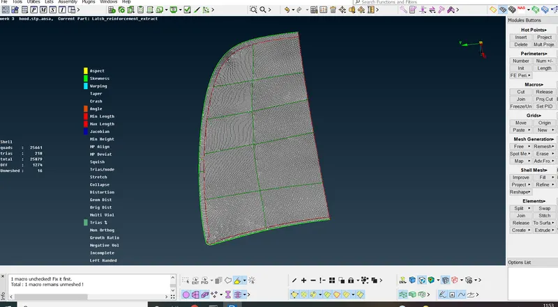
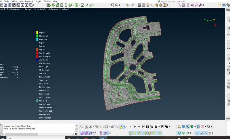
STEP 14:
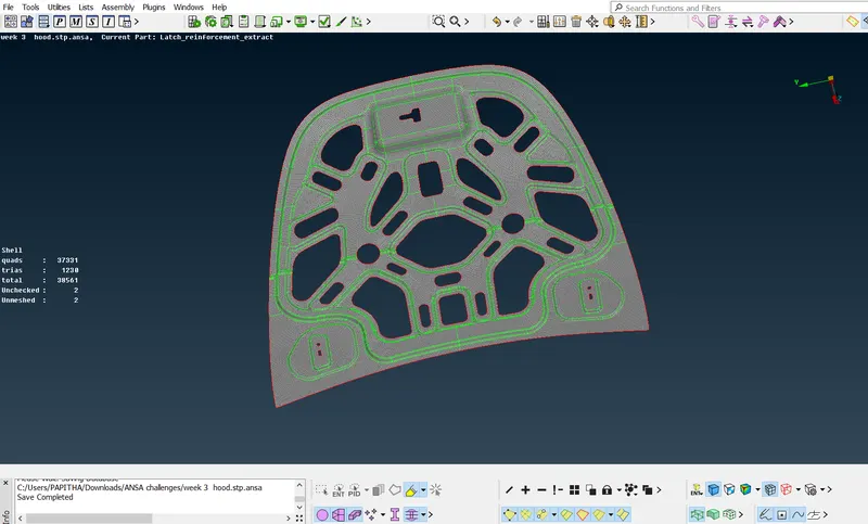
Inner mid extract of given model.
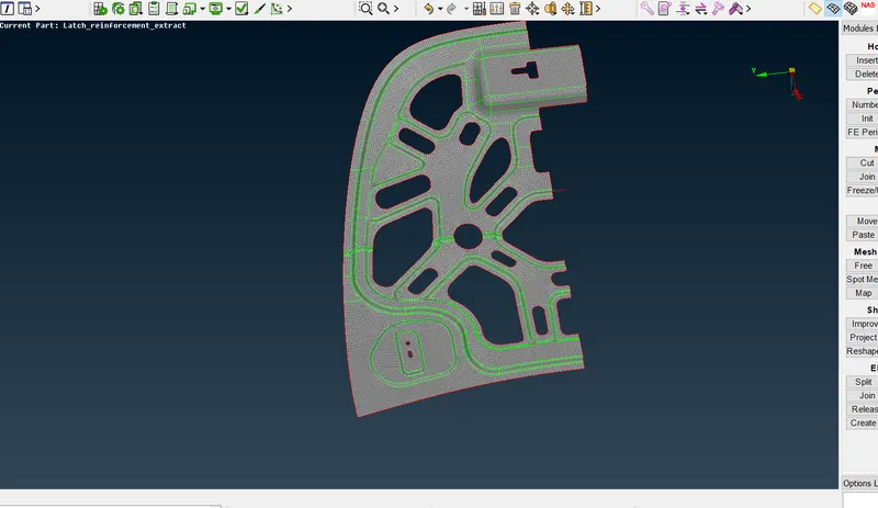
Element quality criteria of the model.
STEP 15:
As same for other component.
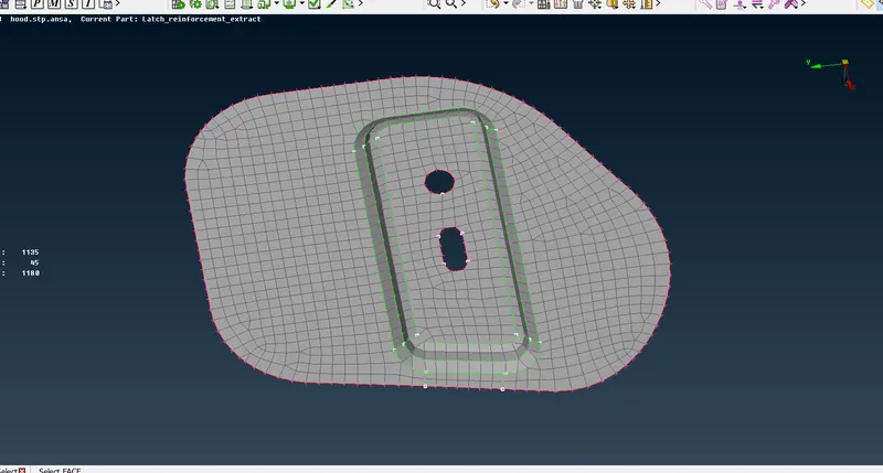
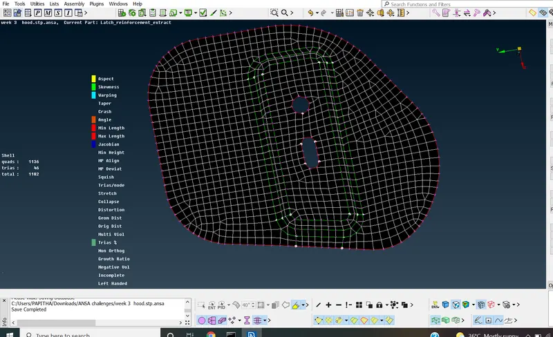
STEP 16:
Assign the thickness of extract mid surface.
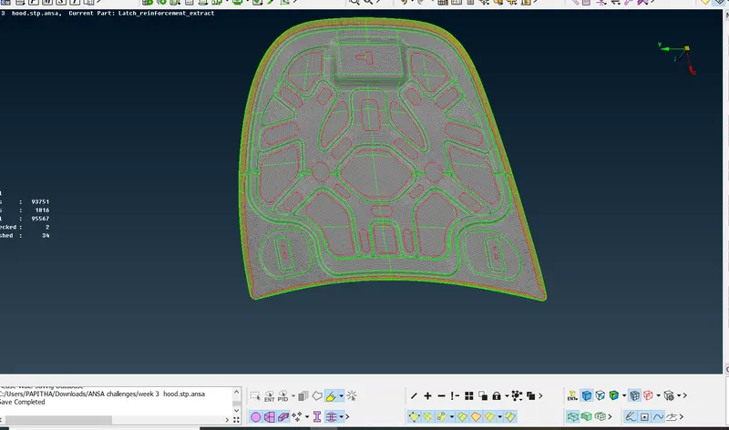
RESULT:
Hence, the model as extract with midsurface with proper mesh flow and good quality criteria with assign thickness.