2D meshing of a Car Hood in ANSA
2D meshing of Car Hood in ANSA
Aim: To mesh the given component according to the given quality criteria
Quality criteria table
|
S.No |
Quality Criteria |
Value |
|
1 |
Target/Average length |
5 |
|
2 |
Minimum Length |
2 |
|
3 |
Maximum Length |
7 |
|
4 |
Aspect |
3 |
|
5 |
Warpage |
15 |
|
6 |
Skewness |
45 |
|
7 |
Jacobian |
0.7 |
|
8 |
Minimum Quad Angle |
45 |
|
9 |
Maximum Quad Angle |
135 |
|
10 |
Minimum Tria Angle |
30 |
|
11 |
Maximum Tria Angle |
120 |
|
10 |
Tria Percentage |
15 |
The given component consists of
- Inner extract body
- Outer extract body
- Hinge reinforcement extract body left
- Hinge reinforcement extract body right
- Latch reinforcement extract body
Model Image
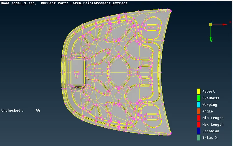
Image 1 Given Model
Meshing Procedure for Sheet Metal Components
Since the sheet metal components have uniform thickness and the thickness is very less when compared to other dimensions of the component and hence it is considered as 2-D Component. Therefore, to mesh these components Midsurface Meshing is done. Midsurface Meshing is the process of meshing 2-D components by meshing the mid surface generated from the component and assigned thickness to the mesh. Midsurface meshing helps in reducing the meshing time when compared with 3-D meshing for the same component. Also, it reduces the simulation time.
Meshing Procedure
1. Genration of Midsurface
2. Geometry Cleanup
3. Finding the symmetric components and deleting it half part
4. Meshing
5. Reflecting the Mesh for the Symmetric Parts.
Meshing Rules
1. The mesh should look smooth and regular.
2. Coarser mesh is to be used for the simple surface area and comparative finer mesh for the complicated surface area.
3. Back-to-back trais should be avoided.
4. Two opposite trias near each other should be avoided.
5. No mesh Transition on constant radius fillets/curvatures.
6. Tria elements at the outer edge/holes are to be avoided.
7. Avoid Tria elements connected to hole-free edge
8. Circular holes are much important in Durability, Fatigue, and NVH analysis. So it should be modeled carefully with at least one layer of quad elements around the periphery of a circular hole. Tria elements will add stiffness so it is not desired to have tria elements.
Step 1: Genration of Midsurface
First the model is checked for any geometrical errors and is cleaned using the Hot Points, Cons and Faces tools. After clearing the errors in the model the midsurface is generated using the Mid.Surface tool in the Faces Tools(Refer to the below image)
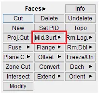
Image 1.1 Midsurface Tool
To Create the midsurface of any component
Faces>Mid.Surface>Select the component>Edit areas>Skin Offset.(Refer the below image)
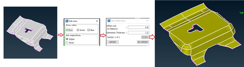
Image 1.2 Midsurface
Midsurface of the rest of the components are generated using the same way. Below images show the middsurface of the rest of the components.
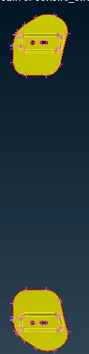
Image 1.3 Latch Reinforcement
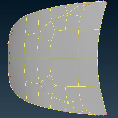
Image 1.4 Outer Extract
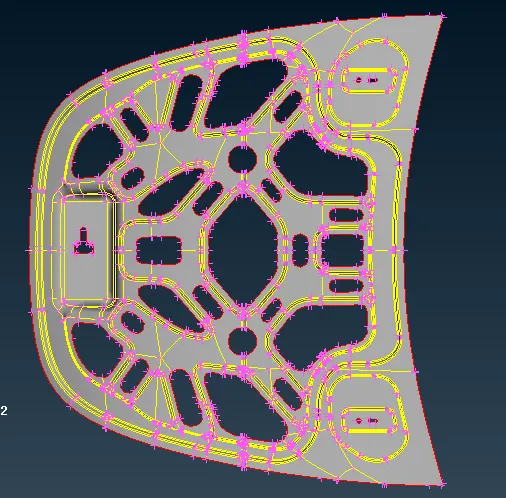
Image 1.5 Inner Extract
Step 2: Geometry Cleanup
After extracting the midsurface of all the components, midsurfaces all the components are checked for any topological errors. Also some double cons are suppressed so as to get good mesh flow.
Tools used in geometry cleanup are Delete in Hot points, Release in CONS, Cut, Topo, Proj.cut, Dach in Faces.
Delete is used to delete unnecessary hot points in the cons.
Release is used to release the double or triple cons
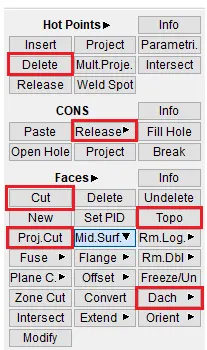
Image 2.1 Geometry Cleanup Tools
Below image shows the images of the components before and after geometry cleanup.
1. Inner Extract
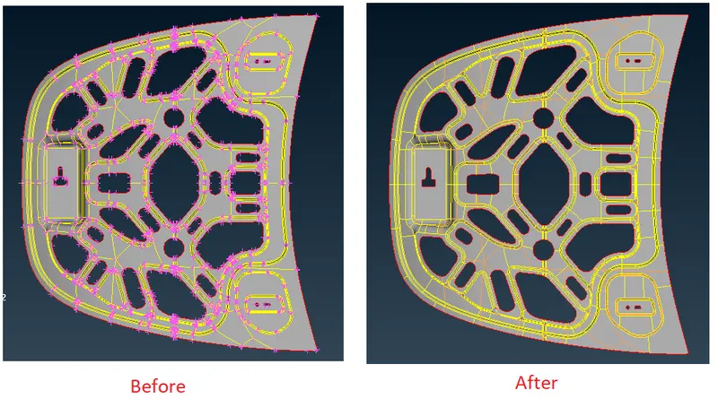
Image 2.2 Inner Extract
2. Outer Extract
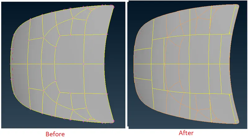
Image 2.3 Outer Extract
3. Latch Reinforcement
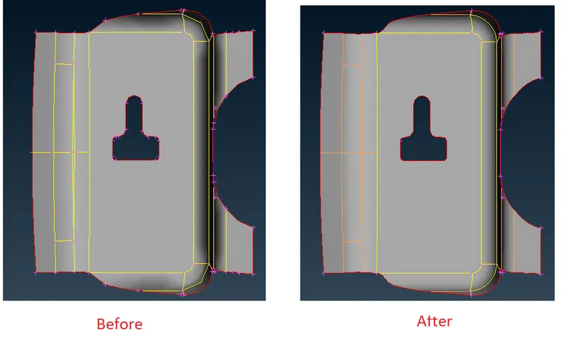
Image 2.4 Latch Reinforcement
4. Hinge Reinforcement
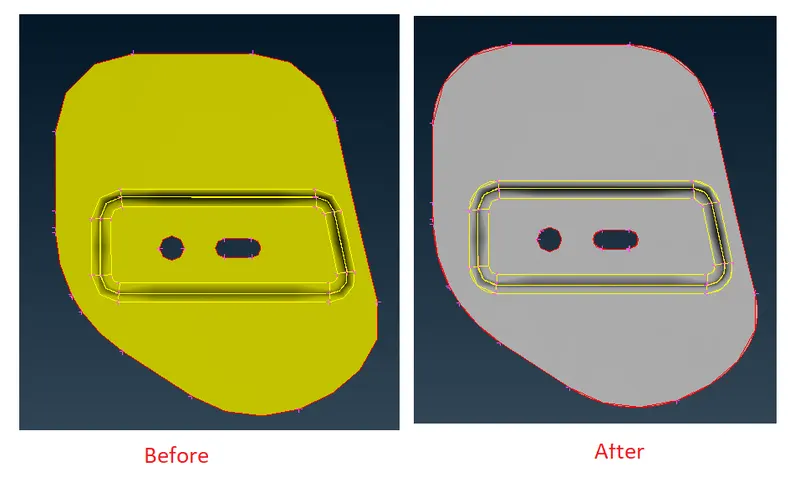
Image 2.5 Hinge Reinforcement
Step 3: Meshing the midsurfaces
Since some components are symmetric and hence half of that component is deleted and the remaining half is meshed and reflected. Below images shows the images of the Symmetric components.
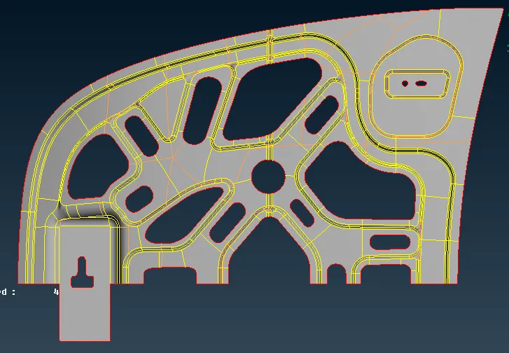
Image 3.1 Inner exract
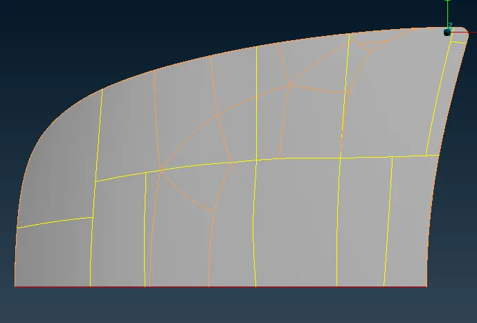
Image 3.2 Outer Extract
To mesh the components the tab is changed from topo mode to meshing mode by clicking the meshing mode icon. In the Meshing tab, Best Mesh tool is used to mesh the components. And to get the better mesh is the Best mesh didn't give good mesh Improve mesh, Reconstruct Tools are used to get good mesh.
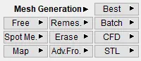
Image 3.3 Meshing Tool
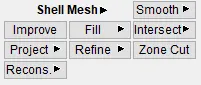
Image 3.4 Reconstruct and Improve mesh tool
Before meshing the component the quality criteria is uploaded. Below image shows the image show the quality criteria uploaded before meshing.
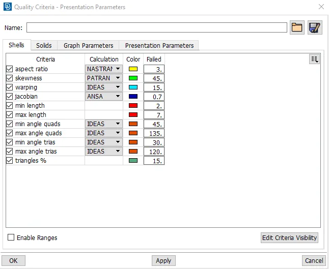
Image 3.5 Quality Criteria
After adding the quality criteria, the mesh parameters are to be added. Below image show the image of the mesh parameters.
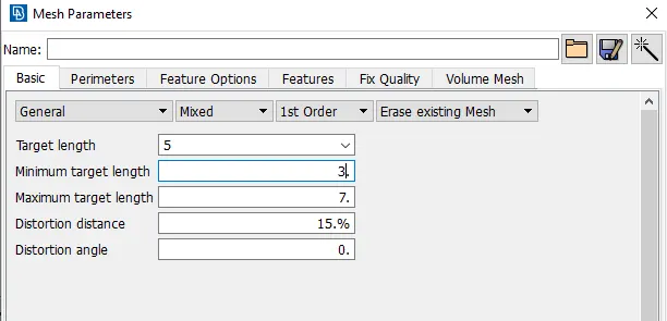
Image 3.6 Mesh Parameters
After adding the mesh parameters, all the components are meshed. Below images shows the image of the meshed component.
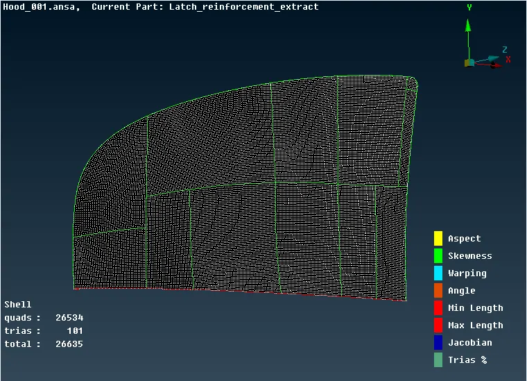
Image 3.7 Inner Extract Half Mesh.
Step 4: Reflecting the mesh
Transform option is used to mirror the half meshed component.
To reflect the mesh Transform>Copy>Select the components>Symmetry>Mirror 3 points plane> Select 3 points on the edge of the half mesh>Apply>Finish.
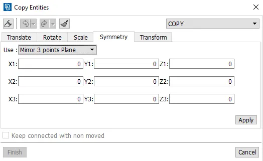
Image 4.1 Mirror Tool
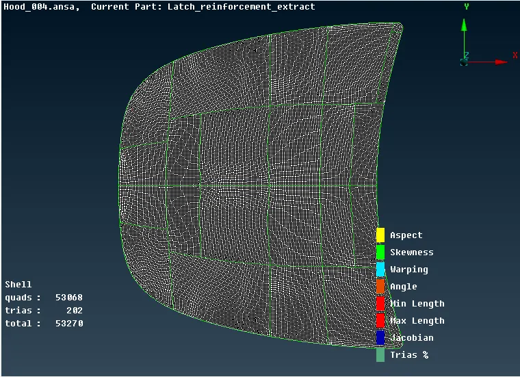
Image 4.2 Outer extract after reflecting the mesh
Similarly all the other components is meshed. Below image shows the meshed components.
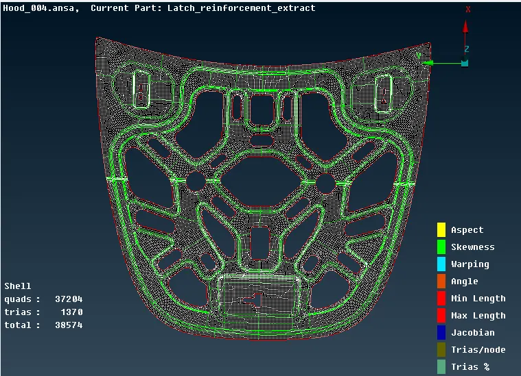
Image 4.3 Inner Extract
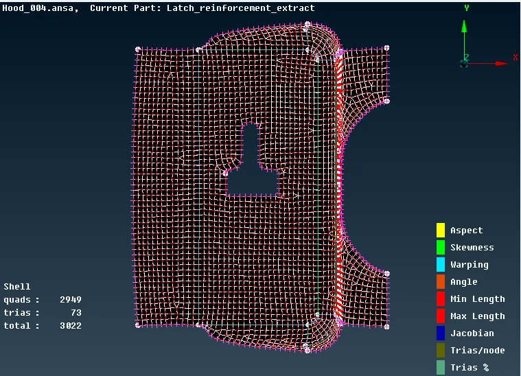
Image 4.4 Latch Reinforcement
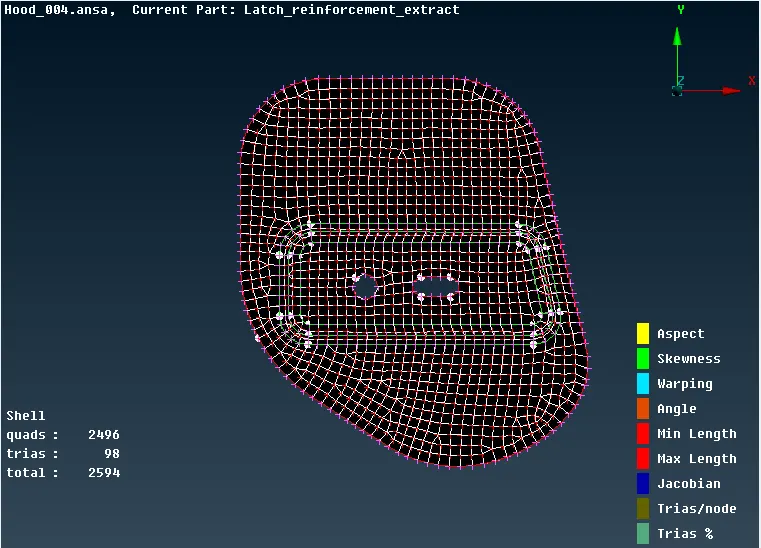
Image 4.5 Hinge Reinforcement
Result:
For the given model, the midsurface for all the component is generated and checked for geometrical error and mesh is done on the midsurface with the given quality criteria.