Week 3 - 2D meshing for Sheet metal
OBJECTIVE
The objective of this assignment is to take the midsurface of the hood of the car and then mesh it with a target element length of 5 & satisfying the quality criteria given below.
| sl no | quality criteria | Value |
| 1 | Target/average length | 5 |
| 2 | Minimum length | 2 |
| 3 | Maximum length | 7 |
| 4 | Aspect ratio | 3 |
| 5 | Warpage | 15 |
| 6 | Skewness | 45 |
| 7 | Jacobian | 0.7 |
| 8 | Minimum quad angle | 45 |
| 9 | Maximum quad angle | 135 |
| 10 | Minimum tria angle | 30 |
| 11 | Maximum tria angle | 120 |
| 12 | Tria percentage | 15 |
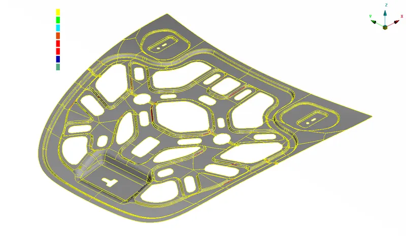
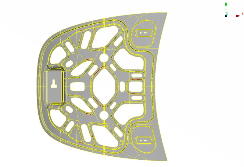
The cad model image of the car hood is shown below.
PROCEDURE
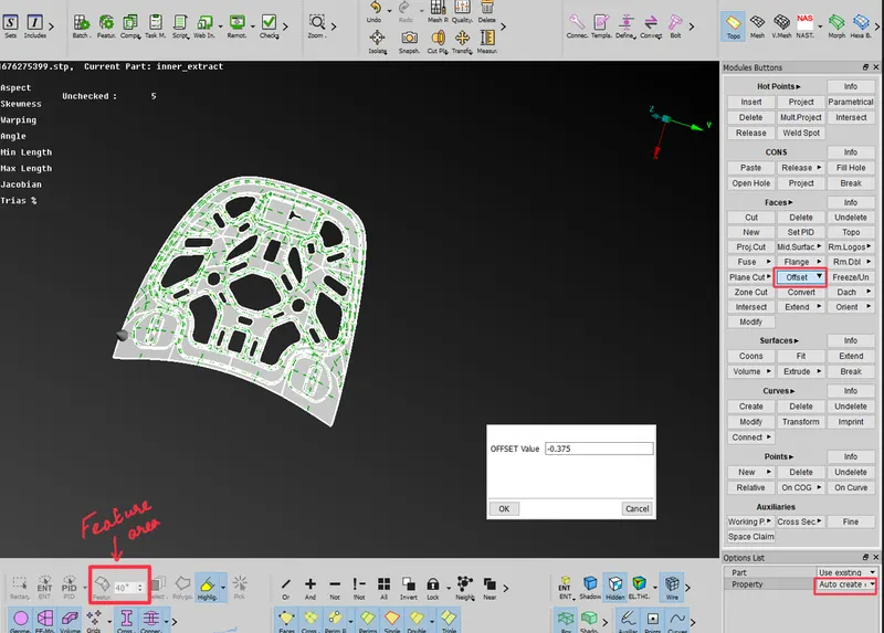
The cad model is first imported into ansa. The imported model contains numerours geometrial errors so we need to first find all the geometrical errors and then clean it. The midsurface can be generated using manually offsetting one side of the face or can be generated automatically using midsurface >skin (TOPO>faces>midsurface>skin) option present in topology module. The automatic generation of midsurface requires that the volume is closed ,so there shouldnt be any geometrical errors. Here we go with the manual surface offset methord since it is saves time. To manually offset the surface we use the offset> faces option(TOPO>faces offset> faces). For easy selection of one side of the model we use feature area selection option. During offfseting a new property is created for the midsurfcae using auto create once option from the options list tab as shown below.
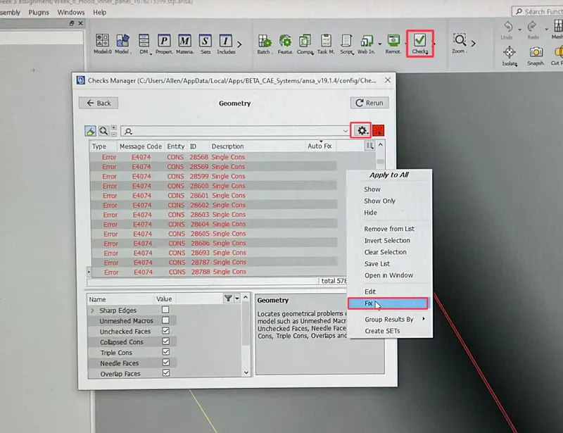
The generated midsurface contains several geometrical errors which needs to be cleaned up. Some of the geometrical errors are shown below. To find the geometry errors easily we use geometry> checks option from the tools bar. Some errors can be easily fixed using thte fix option present in the checks manager as shown below.The midsurface was also assigned appropriate thickness in the properties tab.
Some of the geometrical errors that were present are shown below.
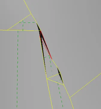
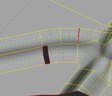
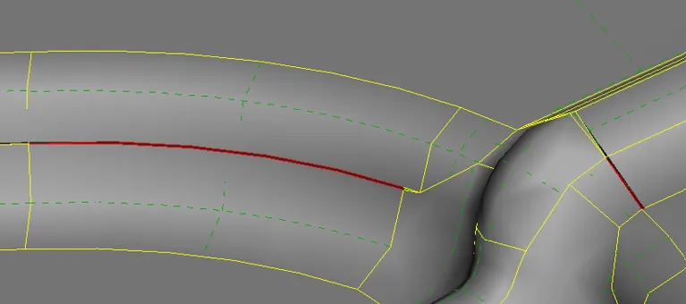
Most of these errors can easily be fixed using various tools like faces>new>coons or fitted, faces>cut, faces>delete faces>topo ,cons> release etc. Since the model has symmetry only one half is required to be meshed so the model is cut in half using faces>plane cut>single option. After the model is cleaned and cut, it is then meshed. The mesh parameters and mesh quality criteria is then assigned. Since our target element length is 5 , shell element length is set to 5 using length option (mesh>perimeters>length). Unwanted feature lines are suppresed using join (mesh>macros>join) tool. The component is then meshed part by part using mesh generation>best tool. The generated mesh may not always be good in quality so to improve quality shellmesh>reconstruct option is used when needed. Some of the common criterias that were followed to obtain a geat quality mesh were
- The tria elements should never be opposite to each other
- No tria elements should be connected back to back
- No tria elements should be on the edge of the geometry
- No tria elements should be on the edge of the geometry
- No tria elements should be near the holes.
- No tria elements should be on the feature and the fillets
- There should be less tria concentration.
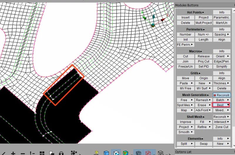
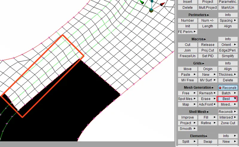
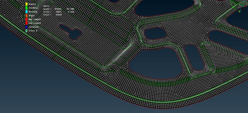
Figure shows mesh generation>best tool in action.
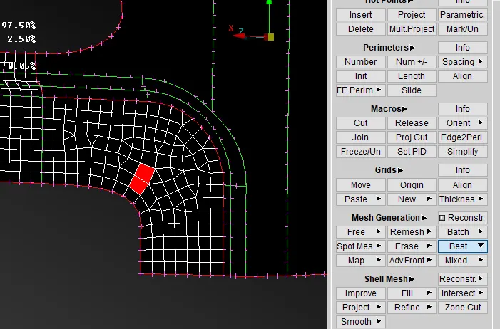
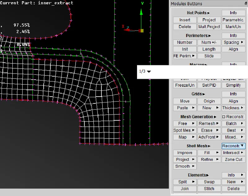
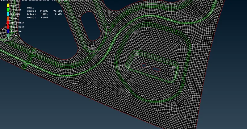
Figure shows shell mesh > reconstruct in action
Most quality issues relating to tria were managed using elements>split, elements>swap, elements>join, grids>paste ,shell mesh>smooth options.Warpage issues were common occourence in areas where there was a sharp turn in geometry, these were fixed by using grids>move tool . Sometimes shell mesh>smooth tool also worked.
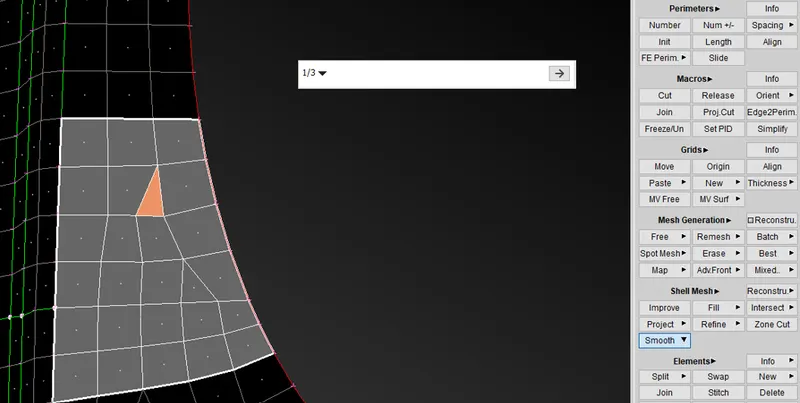
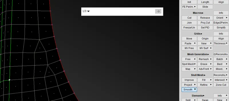
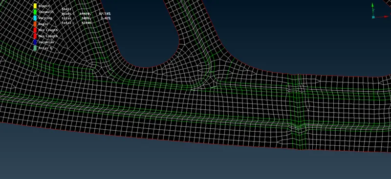
Figure shows smooth tool in action.
Some other tools which were used during meshing were macros>edge to perimeter, grids>origin ,mesh generation>erase, macros>cut etc.. After meshing one side , the other side is reflected to form the complete model using the symmetry option available in transform command. After symmetry operation topology operation is performed to connect the two halves together. After meshing the model and correcting all quality issues it is checked for any connectivity issues between different shells elements using bounds optioin available in the drawing styles module.
RESULT
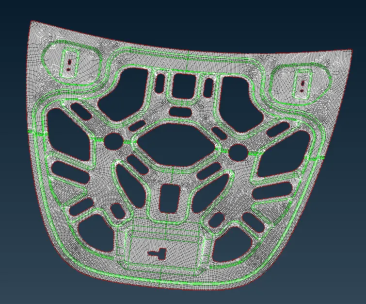
The model was successfully meshed satisfying all the quality criterias .The final meshed model is shown below.