Ansa Week 3 challenge- 2D meshing for HOOD Component
AIM; Perform the topology geometrical cleanup and generate the mesh on the component according to the given Quality criteria in the Ansa GUI.
OBJECTIVE;
- All the 2D elements in your model should clear the above mentioned quality criteria and the features in the model have to be captured properly with good mesh flow.
|
S.No |
Quality Criteria |
Value |
|
1 |
Target/Average length |
5 |
|
2 |
Minimum Length |
2 |
|
3 |
Maximum Length |
7 |
|
4 |
Aspect |
3 |
|
5 |
Warpage |
15 |
|
6 |
Skewness |
45 |
|
7 |
Jacobian |
0.7 |
|
8 |
Minimum Quad Angle |
45 |
|
9 |
Maximum Quad Angle |
135 |
|
10 |
Minimum Tria Angle |
30 |
|
11 |
Maximum Tria Angle |
120 |
|
10 |
Tria Percentage |
15 |
- Perform the geometry clean up.
- extraction of mid surfaces on the components.
- Remove the unwanted lines and form new cuts according to the usage.
- Generate the mesh on the midsurface plane and statisfy the above mentioned criteria.
Procedure:-
- Import the given model
- Topological Cleanup on the component
- Identify the Model(Measurment)
- Extracting the Mid surface
- Create Set Pid
- Set the Quality Criteria
- Mesh Generation
- For generating the better mesh flow we have to avoid the Trias at the basis on
- symmetrical process
- find out the free edges and topo can be done on these free edges.
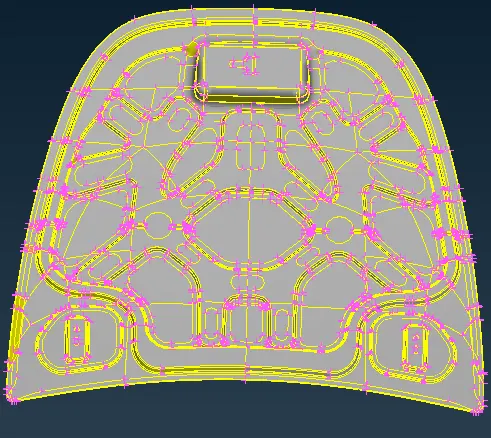
Given Hood model.
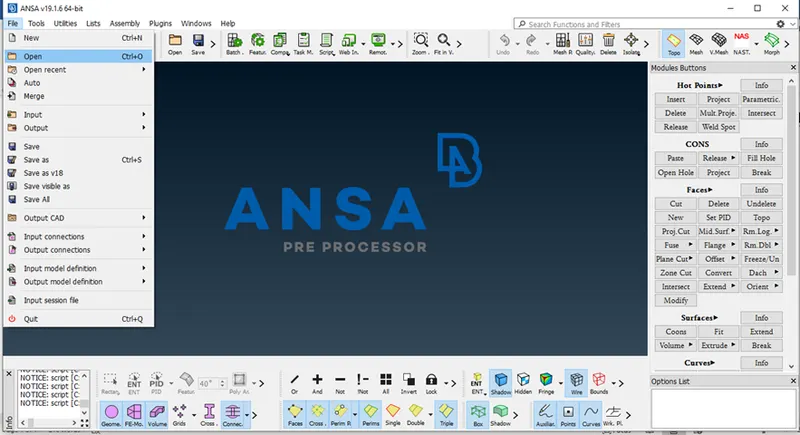
1.IMPORTING THE MODEL;
We need to import the model from drive to ansa by using
File >open >select file >ok.
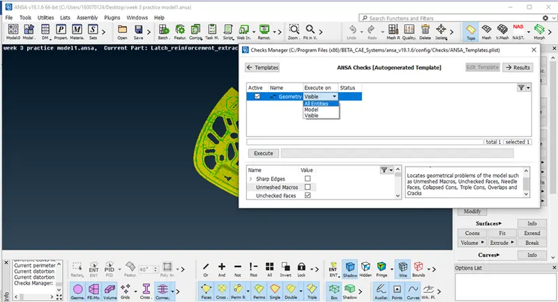
After importing then
2.We need to check geometry;
Tools >check> geometry all entities run
From the below figure window shows the errors in the geometry part such as cracks and other similar issues.
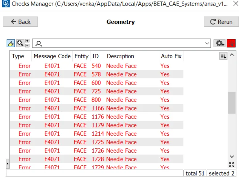
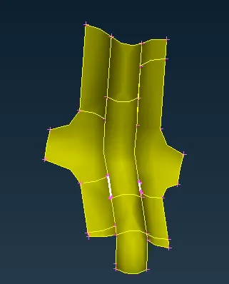
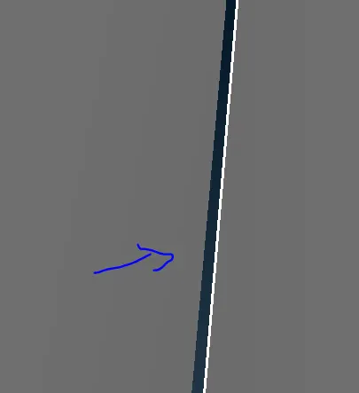
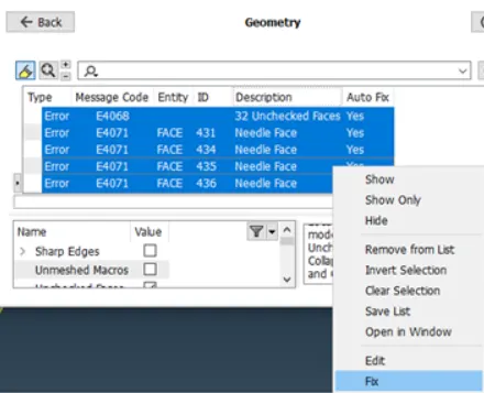
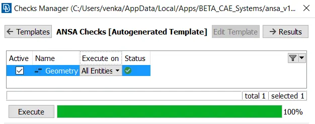
In order to avoid those errors we need to fix them by right click on mouse and a box format will be open, there we can see the option fix.
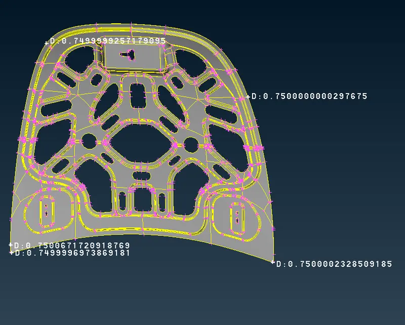
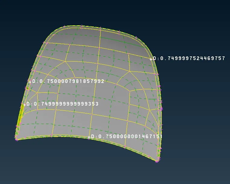
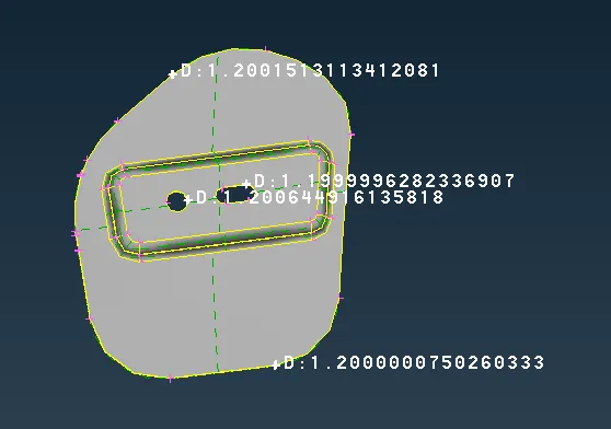
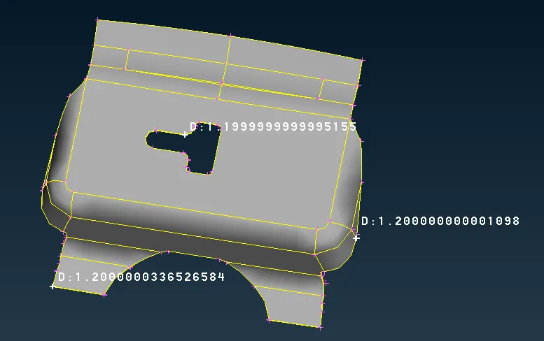
3.Identify the Model(Measurment);
Then next is to check the type of geometry whether the given model is a Plastic or sheet metal component.
we use to measure the thickness at multiple places to understand if the component is sheet metal or plastic.
If the thickness is the same throughout the geometry then it is sheet metal and if the thickness is varying then it is plastic.
4.Extracting the Mid surface;
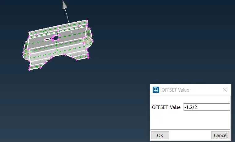
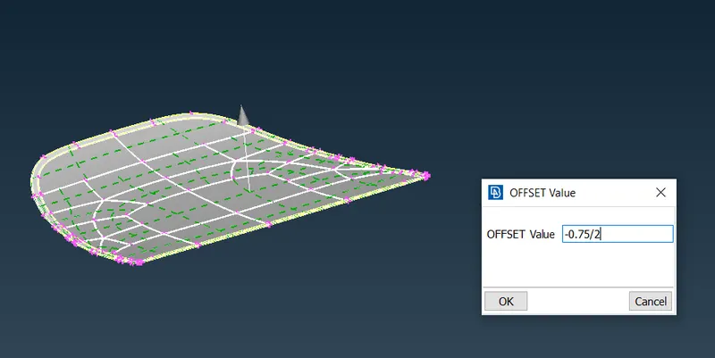
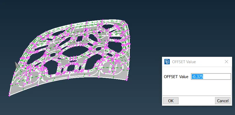
To extract the mid surface we having two options one is automatic midsurface will work on a single mouse click and we having the other option were can extract the middle surface manually by offsetting the surface, either top or bottom to half of its thickness.
In these model we choose the manual offset process.
Go to the Faces > click on offset and select top of the model and mention the offset value and generate the midsurface on the 3D model.
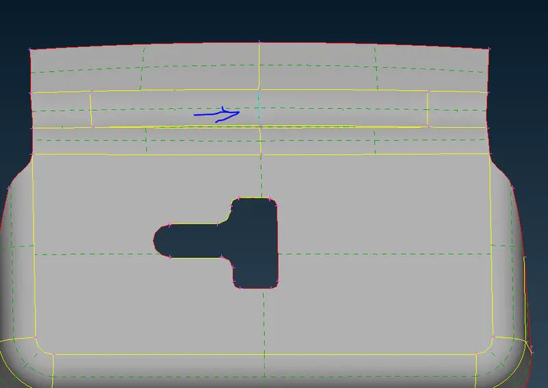
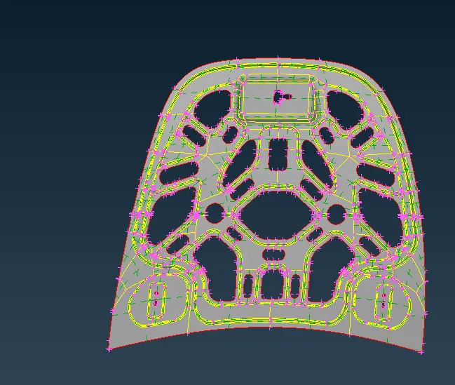
In these mid surface we can see some geometrical errors are present such as forming an triple cons (these will forms were the surfaces are attached with the three layers) and we need to delete those triple cons on the faces of geometry.
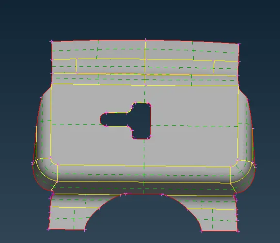
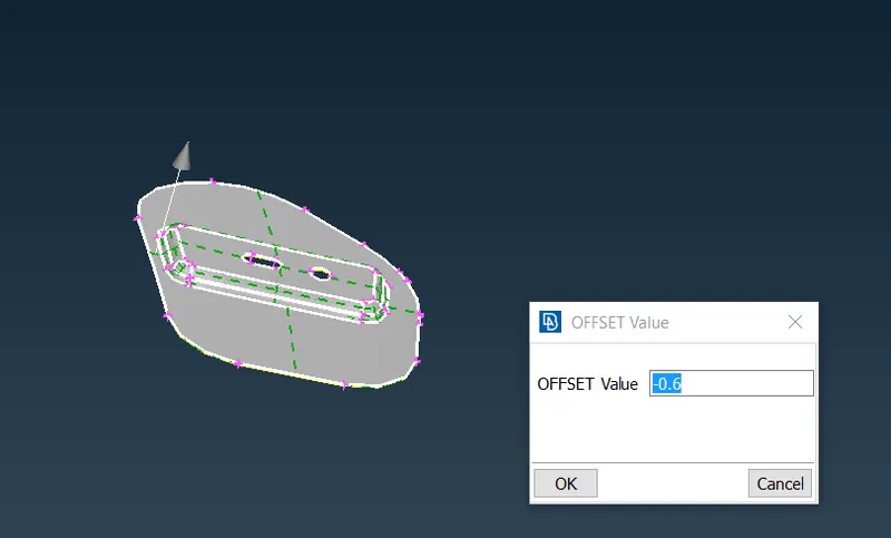
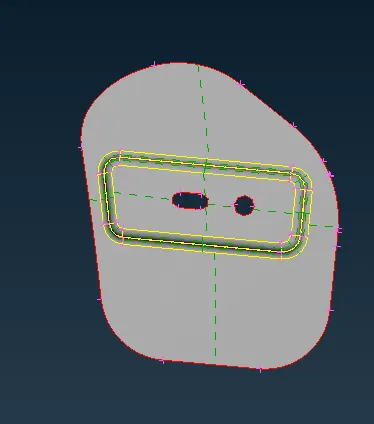
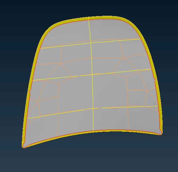
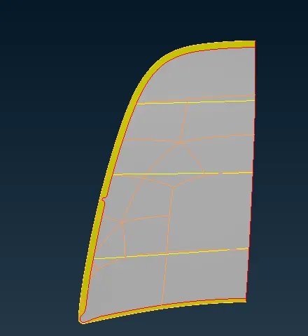
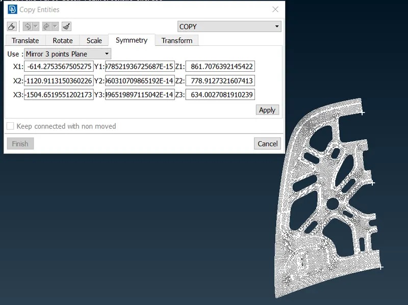
Since the Model is symmerty, we have to delete the other side of the cad geometry for both inner and outer body and after meshing we need to reflect it back by transform option.
5.Create Set Pid;
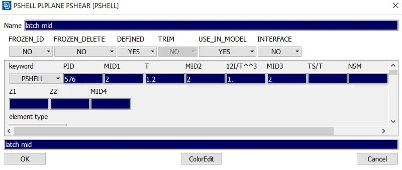
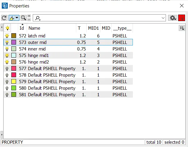
After taking the midsurf to the all components , then create a seperate propertys to each of the models and Assign the proper thickness to the models.
Faces>setpid>select the entity and create the new id > Pshell > mention thickness> ok.
6. Set the Quality Criteria;
Go to utilites > click on Quality > set the parameters >apply >ok.

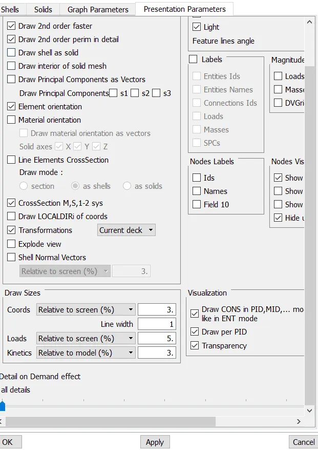
and also set the Target length.
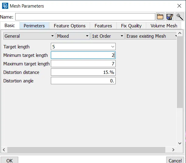
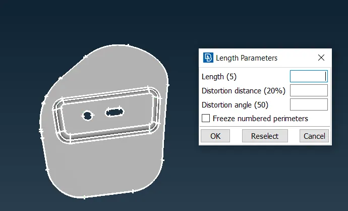
Now we can set the perimeter length as 5 ,according to the target length to all other components.
7.Mesh Generation;
Faces > cut > select the unwnanted lines with right mouse click and remove them.
Before meshing on a model we need to clear all the unwanted constuction lines.
Go to the Mesh generation > click on Best option > select the surface area of the geometry and mesh on them.
Latch model;
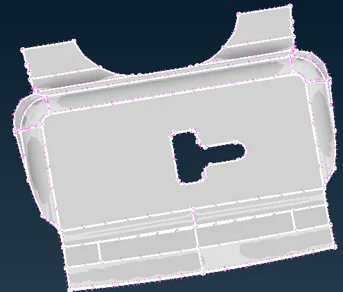
After meshing the component , we reconstruct the mesh on the model inorder to get more uniform and good mesh on the component.
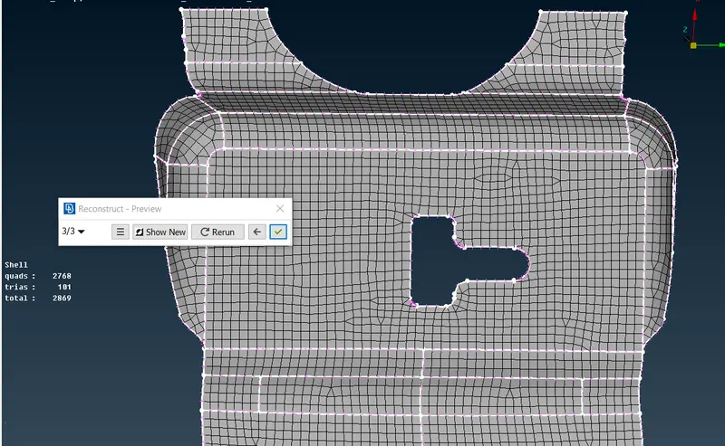
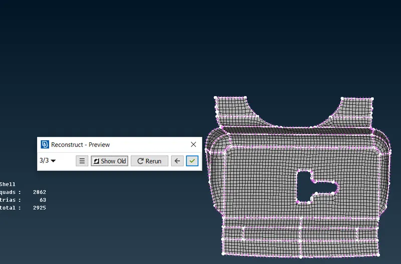
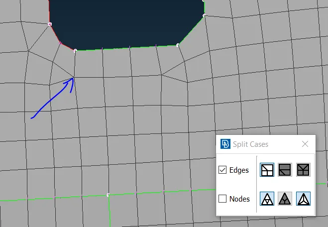
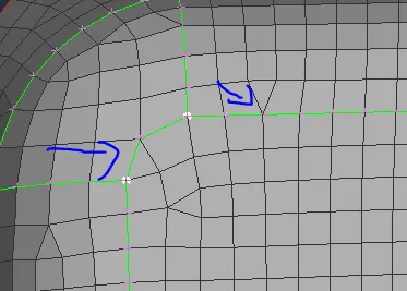
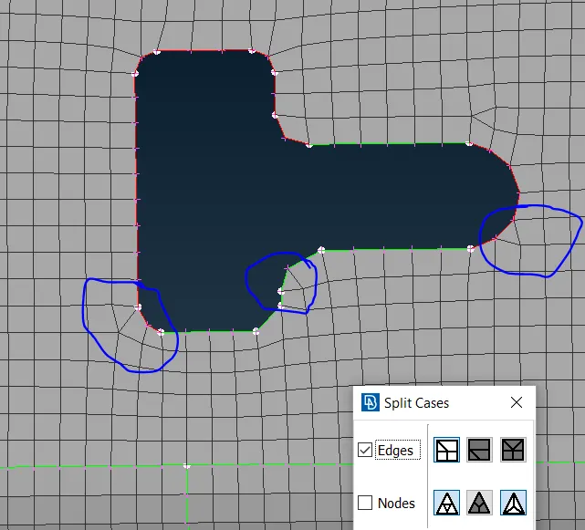
For generating the better mesh flow we have to avoid the Trias at the basis on;
- Avoid the trias which are forming opposite to each other.
- Avoid the trias,near fillet regions.
- Avoid the trias,near the circular holes.
- Avoid the trias,edges of the geometry.
- Avoid the trias,back to back trias.
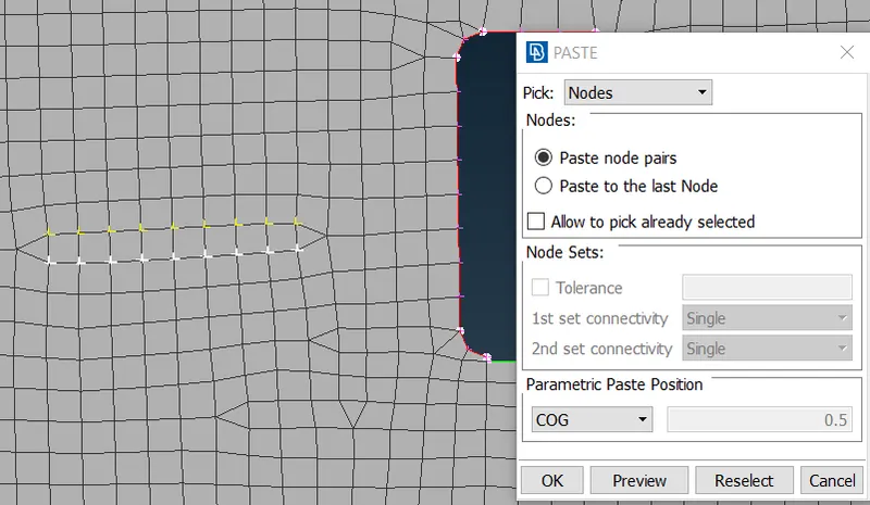
Which will effect the results of the model and these can handled by some tools such as split(use in multiple ways are spilt,swap,join and dividing the quads),paste(use in movement of backward direction of trias).
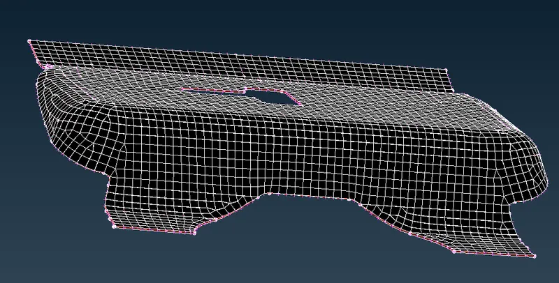
Final mesh component after clearing all the errors.
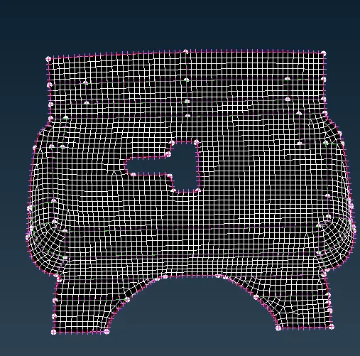
Here we can property of a Latch component, Drawing styles > Select the Drawing mode tool bar , were we can find pid option and set the pid mode and click on it.
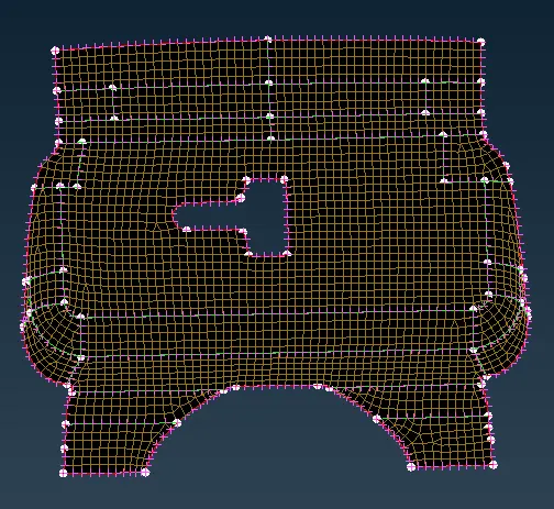
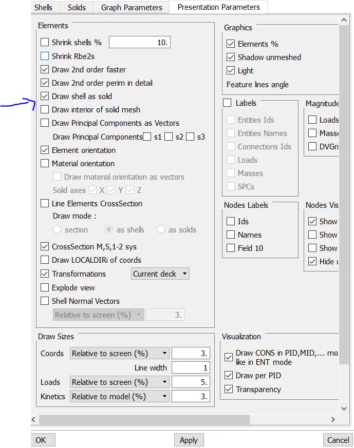
In order to see the thickness of the component go to utilites>Quality > on the draw shell as a solid > ok and in the below image we can see the thickness of the component.
Hinge model1;
Final mesh component after clearing all the errors.
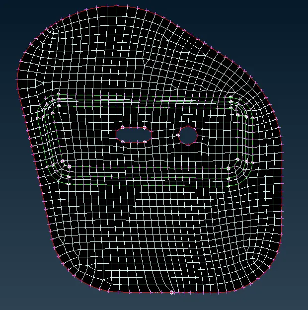
Here we can property of a hinge component, Drawing styles > Select the Drawing mode tool bar , were we can find pid option and set the pid mode and click on it.
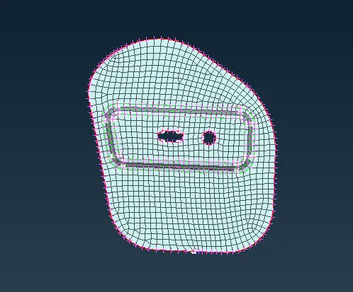
In order to see the thickness of the component go to utilites>Quality > on the draw shell as a solid > ok and in the below image we can see the thickness of the component.
Hinge model2;
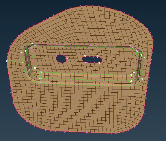
Final mesh component after clearing all the errors.
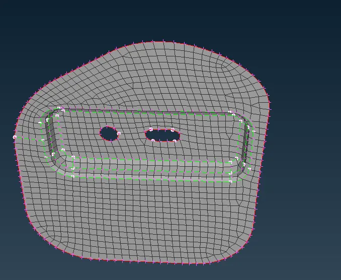
Here we can property of a hinge component, Drawing styles > Select the Drawing mode tool bar , were we can find pid option and set the pid mode and click on it.
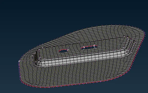
In order to see the thickness of the component go to utilites>Quality > on the draw shell as a solid > ok and in the below image we can see the thickness of the component.
Outer model;
Since the Model is symmerty, we have to delete the other side of the cad geometry for both inner and outer body and after meshing we need to reflect it back by transform option.
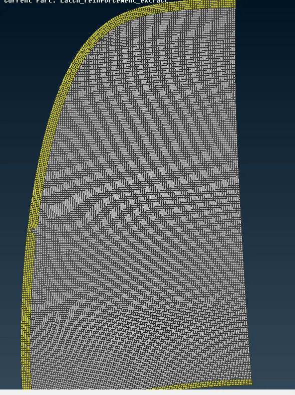
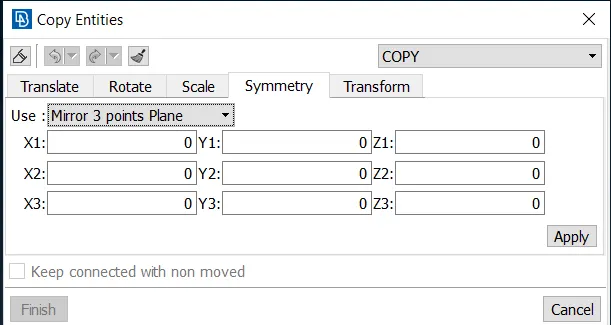
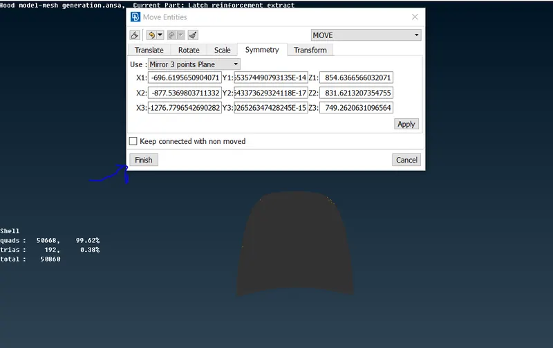
At last click on the finish option in order to reflect the model.
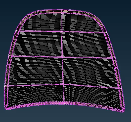
Final mesh component after clearing all the errors.
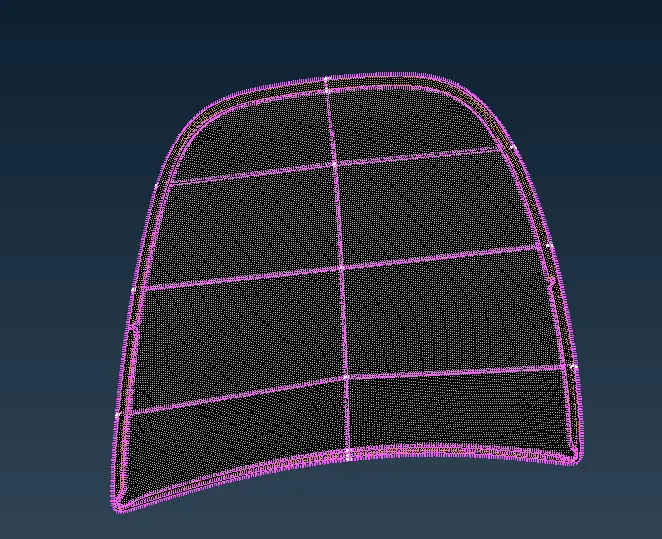
Here we can property of a outer component, Drawing styles > Select the Drawing mode tool bar , were we can find pid option and set the pid mode and click on it.
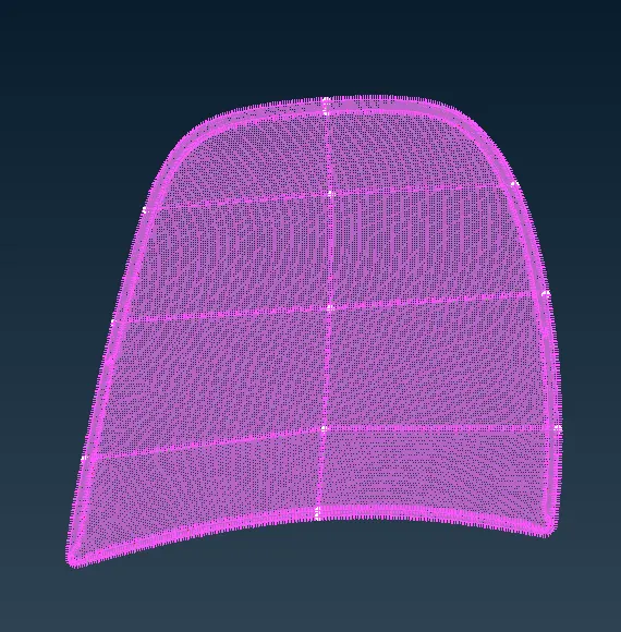
In order to see the thickness of the component go to utilites>Quality > on the draw shell as a solid > ok and in the below image we can see the thickness of the component.
Inner model;
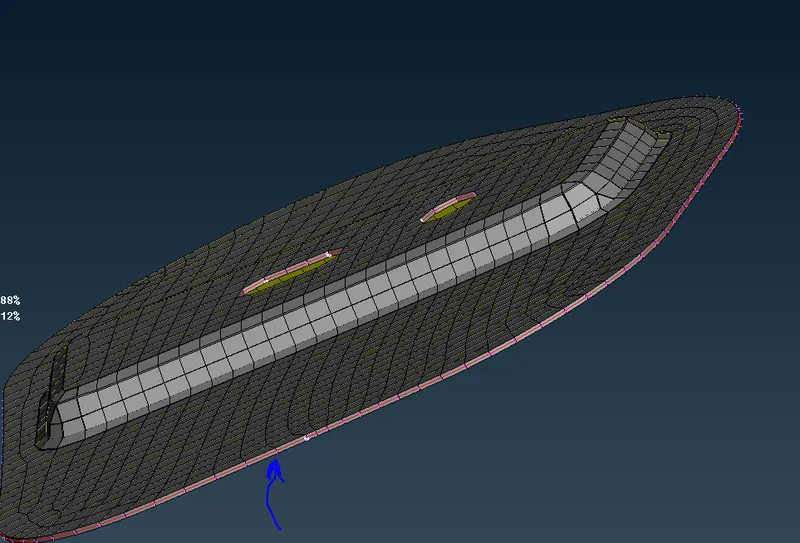
Finally you will see the top surface of the latch part is left with free edges forming.
These free edges (Red Cons) can be converted to Double Con (Yellow Cons) by carrying out a Faces > Topo operation.
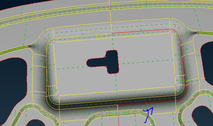
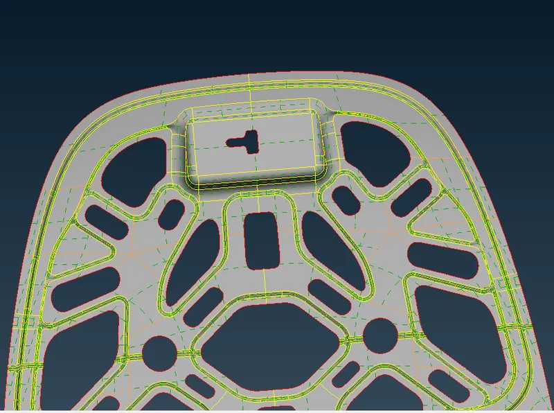
These areas need to be meshed and set the proper flow of mesh on them.
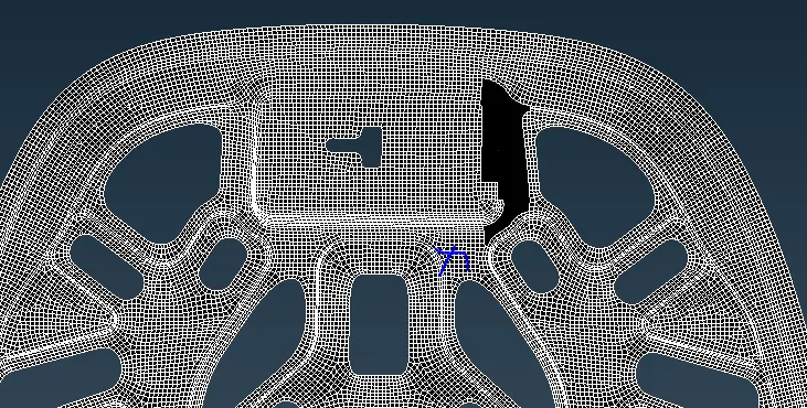
Final mesh component after clearing all the errors.

Here we can property of a inner component, Drawing styles > Select the Drawing mode tool bar , were we can find pid option and set the pid mode and click on it.
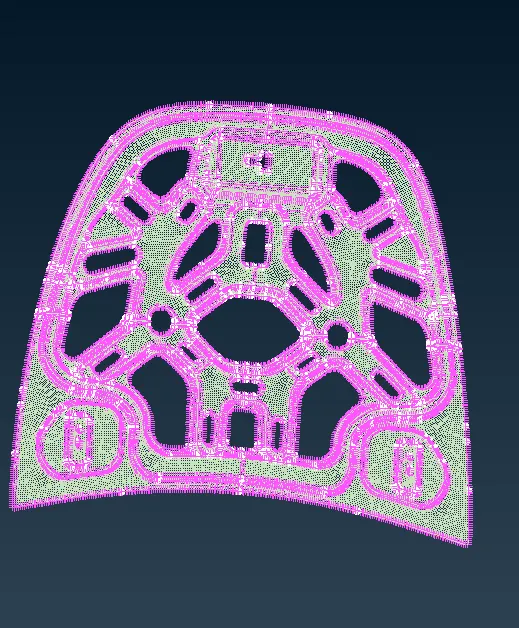
In order to see the thickness of the component go to utilites>Quality > on the draw shell as a solid > ok and in the below image we can see the thickness of the component.
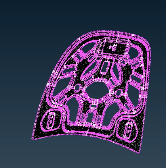
CONCLUSION;
- Before the performing the mesh on the model component, first model should ready with all topological cleanups.
- In order to acheive good mesh, remove the trias at edges, opposite trias, back to back trais, trias at the circular sections and fillet regions need to avoided.
- Use smooth option, for smoothing the mesh in an uniform manner.
- Mesh should passes all the Quality criteria parameters.
- Meshing the symmetrical axis of the compenets, saves a lot time.
CHALLENGE LINK;
https://drive.google.com/file/d/1-PME7eFRvnHlDv8ncKn0zY-RhXj5wtsw/view?usp=sharing