Week 3 - 2D meshing for sheet metal
Aim: 2D mesh of sheet metal using ANSA.
Steps:
- Import geometry by pressing “Ctrl + O” to open/import the file.
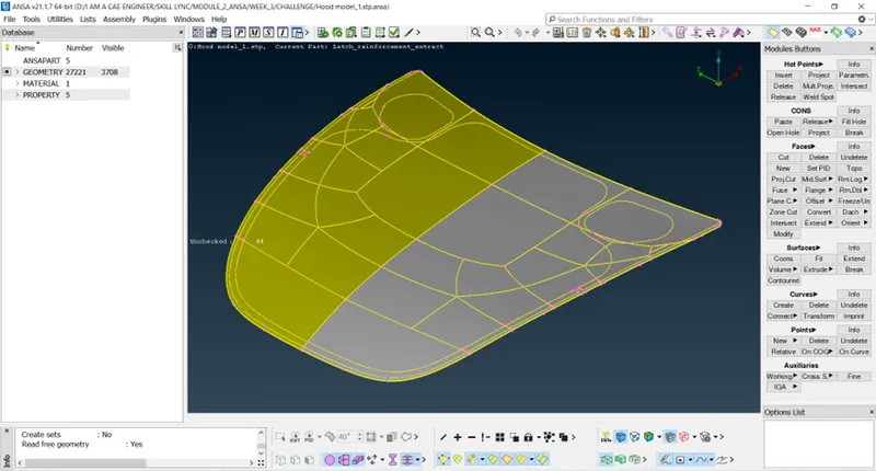
- The entity is not oriented properly as per color, so use “orient option” from topo module.
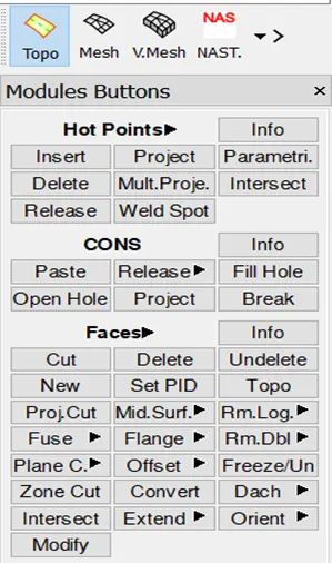
- Select visible in orient option and the geometry will oriented properly according to color.
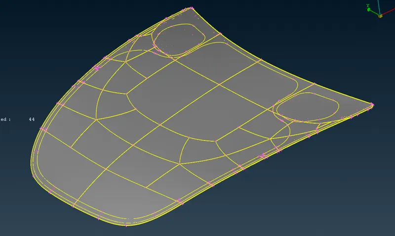
- Now lets check the geometry for surfaces properly stitched together or not, by going to “Checks manager” from Tools bar.
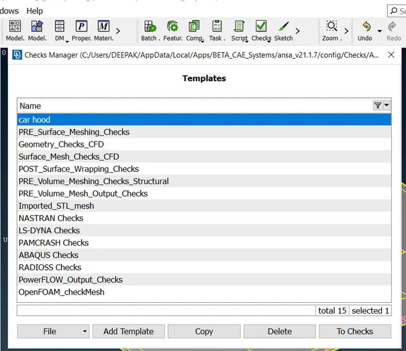
- Here you can create new template or use existing template as per geometry checking.
- We will create a new template and name it as “car hood” as shown in image.
- Double click on it and select the appropriate check box for checking different properties of model.
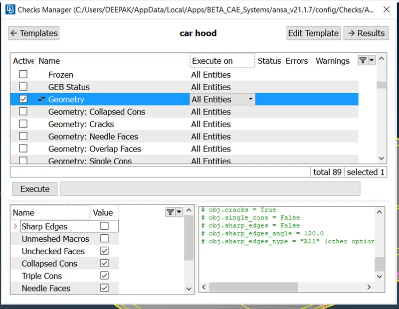
- We will check geometry only, in this case and click on execute.
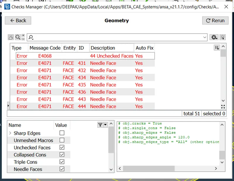
- This shows the result that there are errors in this model, we have to fix it.
- Select all the errors and right click on it and select fix.
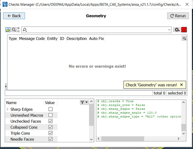
EXTRACTING MID SURFACE INDIVIDUALLY:
- Press ctrl + P to open property manager and hide all other component by clicking on the bulb icon.
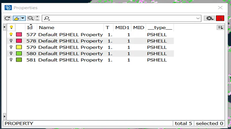
- We will start with the inner panel component.
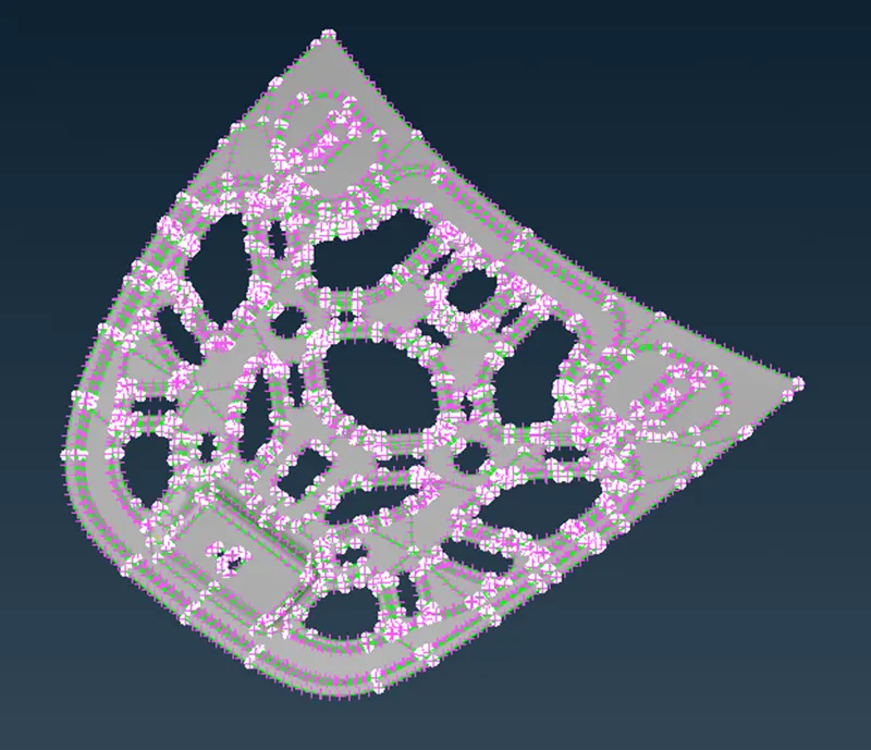
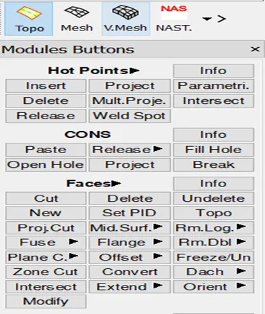
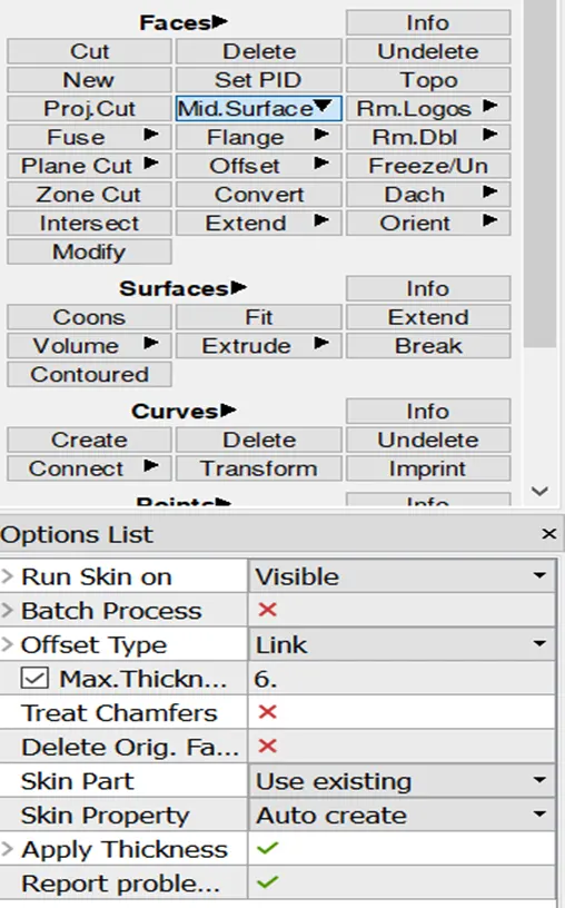
- Go to TOPO module, select Mid surface from Faces panel.
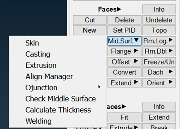
- Select skin from here and select the displayed surfaces from screen and press enter.
- But before doing this, first check the thickness of the sheet metal component by going to utilities and selecting measure.
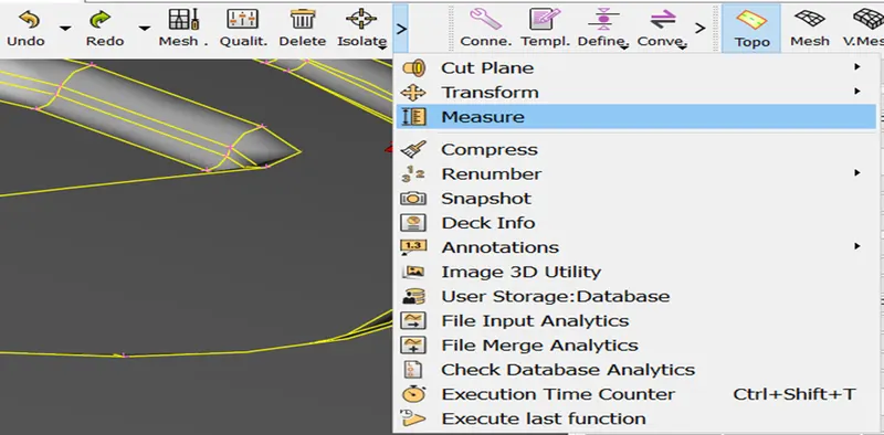
- Select two nodes from which you want to measure distance.
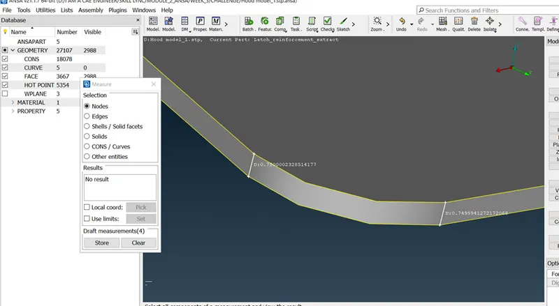
- The distance or thickness is showing 0.75mm approx.
- Now go to mid surface and select skin and select the displayed entities and press enter.
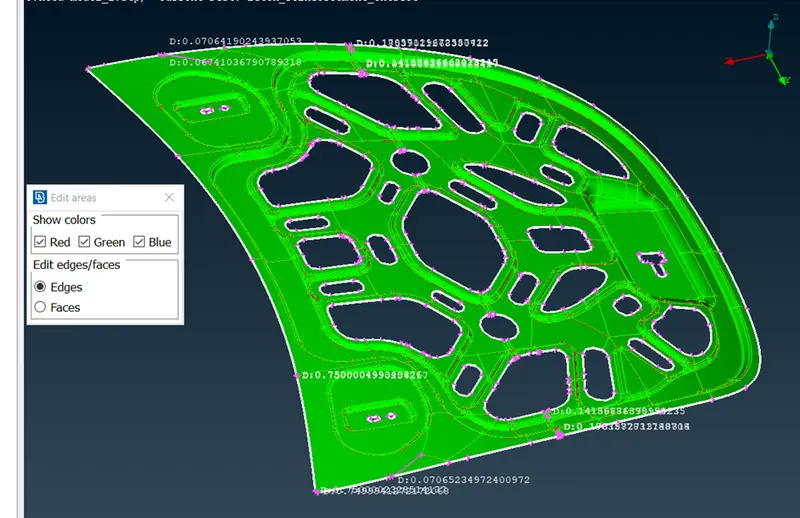
- This shows on screen indicating, red color as one side of componet, green as opposite side of red and blue as the thickness surface of component.
- If these are not properly set, then the mid extraction will fail.
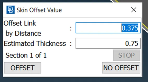
- Again press enter and this dialouge box will pop up, showing the total thickness and the mid surface offset distance.
- This is the result after extracting mid surface.
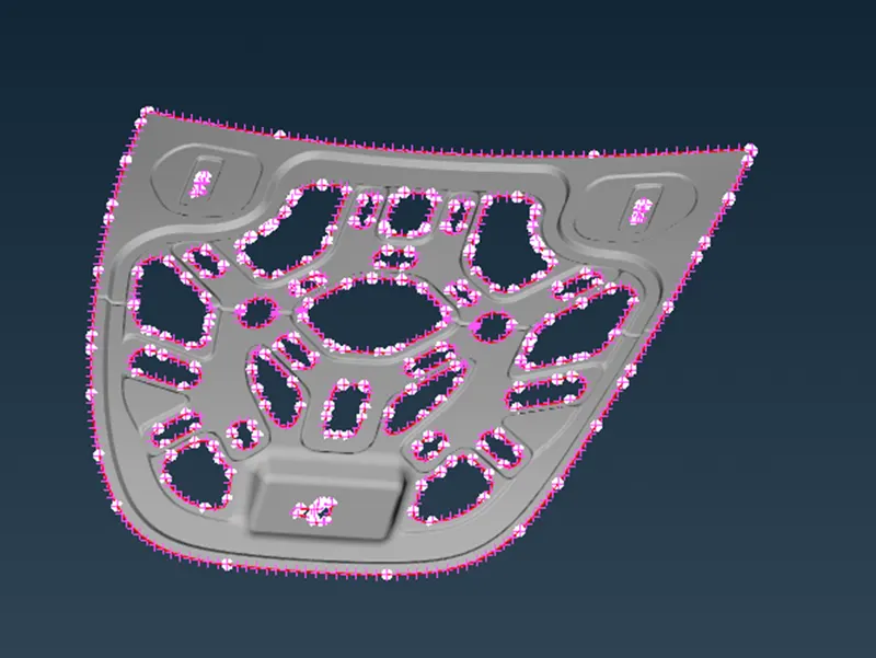
- Extracting mid surface will automatically create a new property with thickness assigned to it automatically.
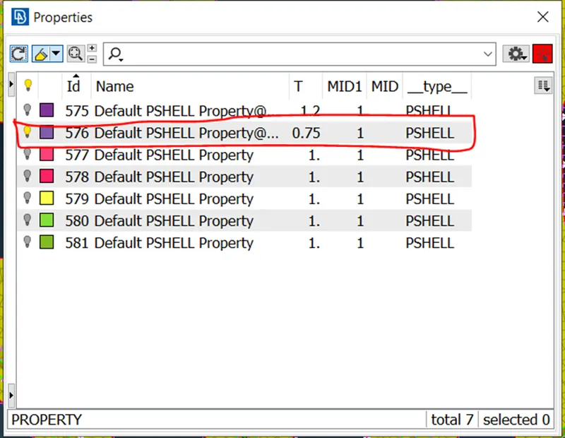
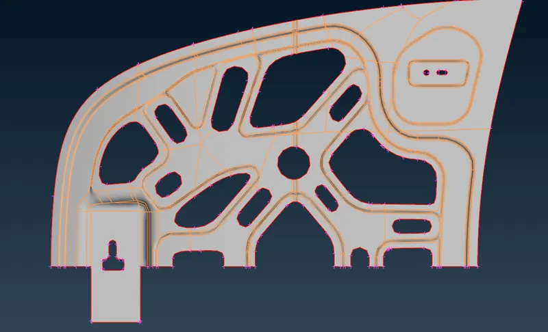
- Delete half of the surfaces as the geometry is symmetrical.
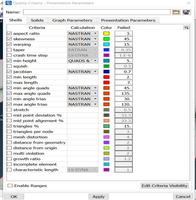
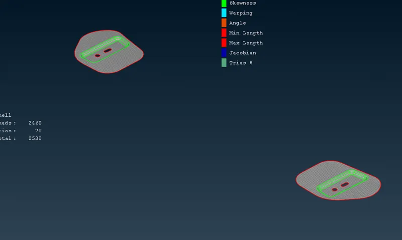
- Now press F11 and set quality criteria as shown.
- Go to mesh module.
- Select length from parameter and select macros from it.
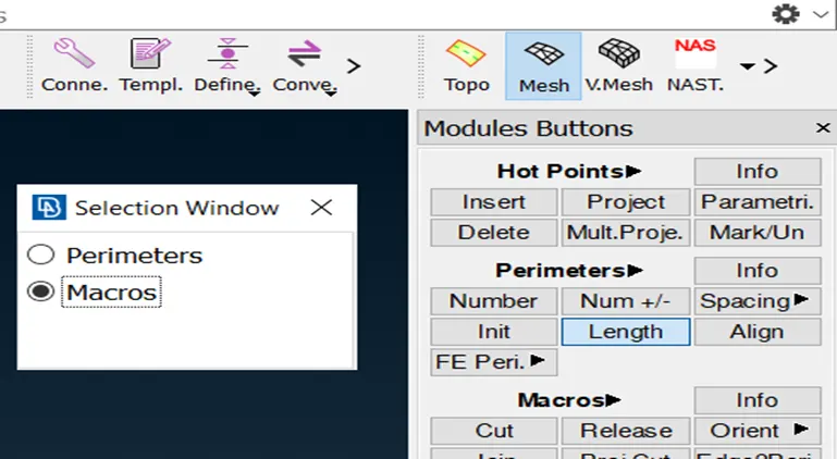
- Select the geometry displayed and press enter. Set length as 5, because it is our target element length.
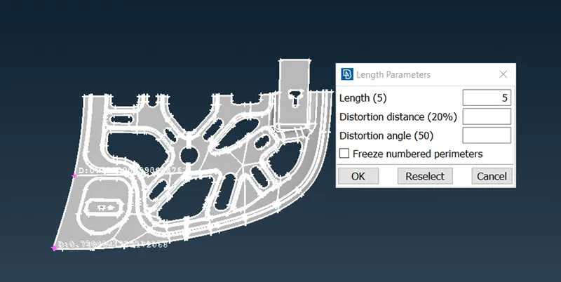 This is done because at first the distance between hot points were not as per target length, so to set the hot points distance as per target length, we use this length parameter option.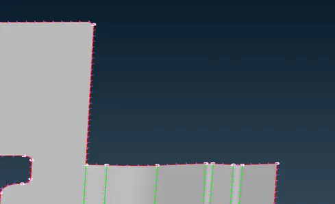
- Do some geometry cleanup by using join and cut tools.
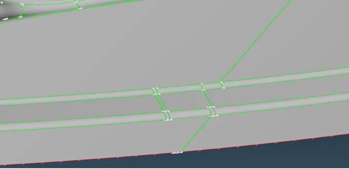
- After geometry clean up, start meshing.
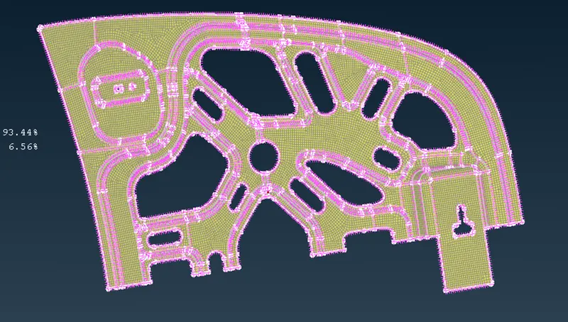
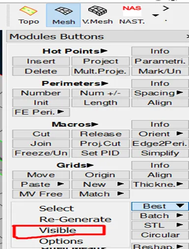
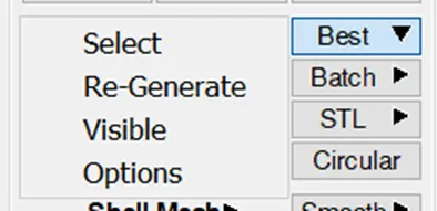
- To do that go to Mesh module, mesh generation, in that use “Best” option as shown in image.
- Select visible and done.
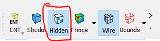
- Mesh will look like this, to view by quality criteria select hidden from drawing styles.
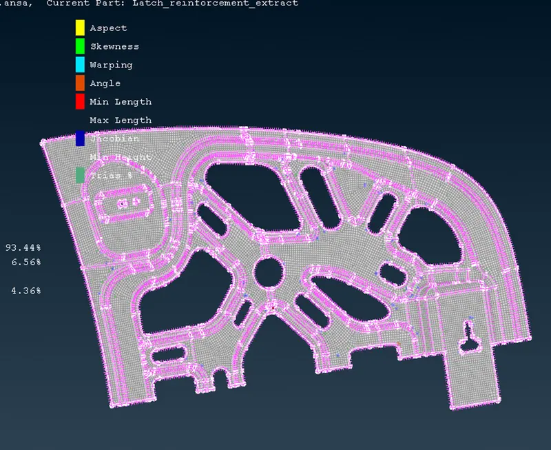
- As per quality criteria, elements will be displayed in different colours, so that the quality of elements can be met by using some tools.
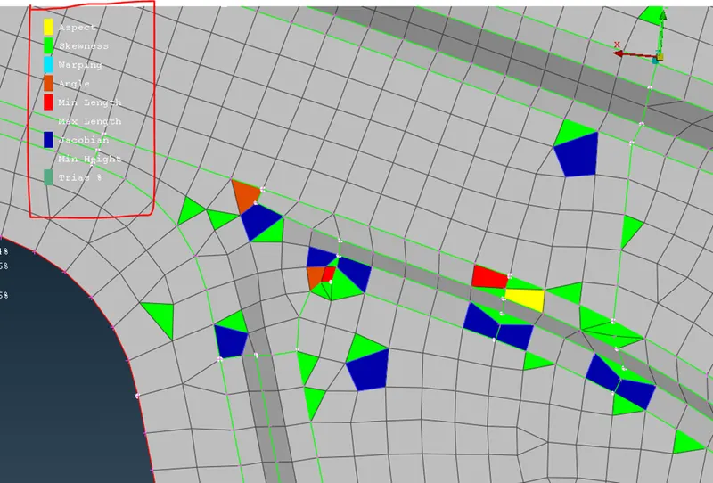
- In this area we can use improve option from shell mesh module button.
- Select elements as shown in image and select reconstruct in dialogue box and press enter.
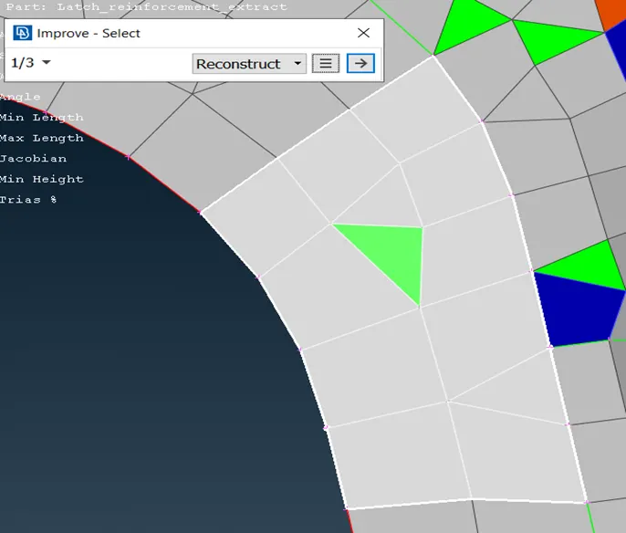
- It will look like this.
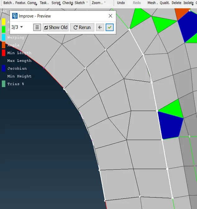
- Like this we can improve quality of elements.
- After improving all the quality criteria, this is the result.
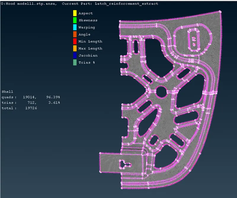
- As you can see no colored elements are seen in this image, so all the quality criteria are met.
- Now, apply symmetry option from transform which is found in assembly toolbar.
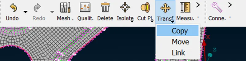
- Use copy from transform.
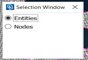
- Select entites on screen that is all the surfaces except which is not symmetrical.
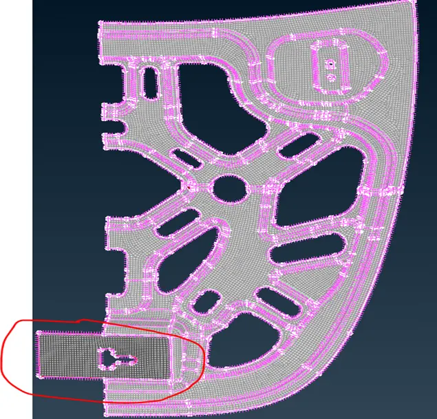
- After selecting press M.M.B, this dialogue box will pop up.
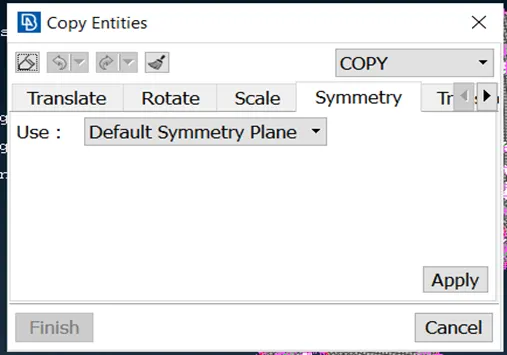
- Select default symmetrical plane and click apply.
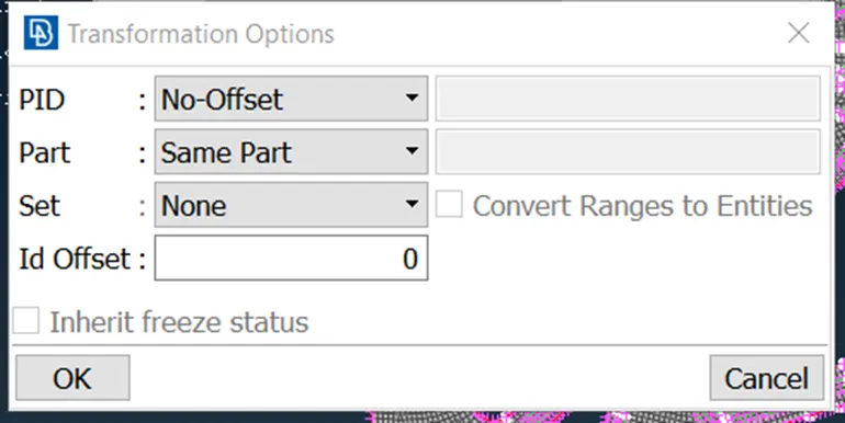
- Click ok.
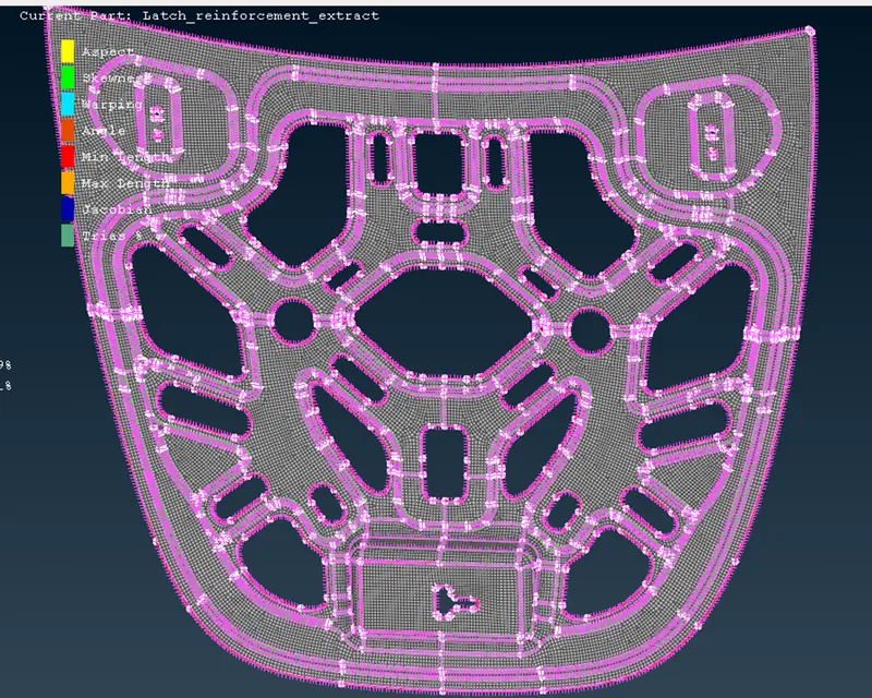
- As you can see the elements are reflected.
- Now switch to shadow drawing style display mode. There you will see red cons.
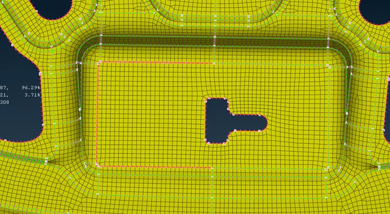
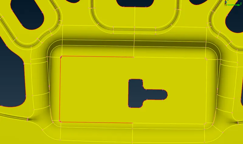
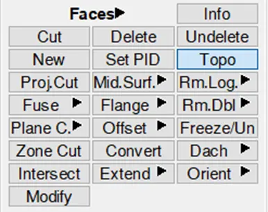
- Now go to topo module and use topo from faces module button to connect the red cons together.
- After selecting the red cons, it will turn into yellow cons but the mesh will be deleted on the particular surface so redo the mesh again on the surface.
- This is the final resul after all the process.
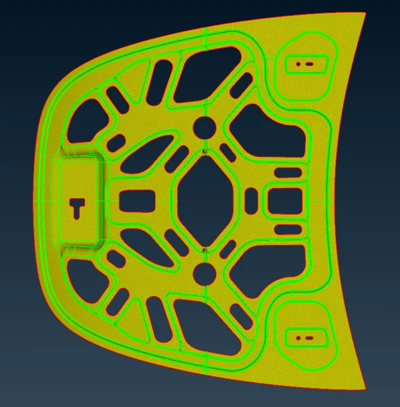
- Now lets repeat all the process from extracting mid surface to generating mesh on different component.
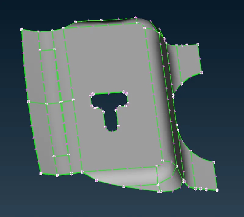
- After extracting mid surface.

- After cleaning up geometry by using join and length option for joining macros area and alter shell element length.
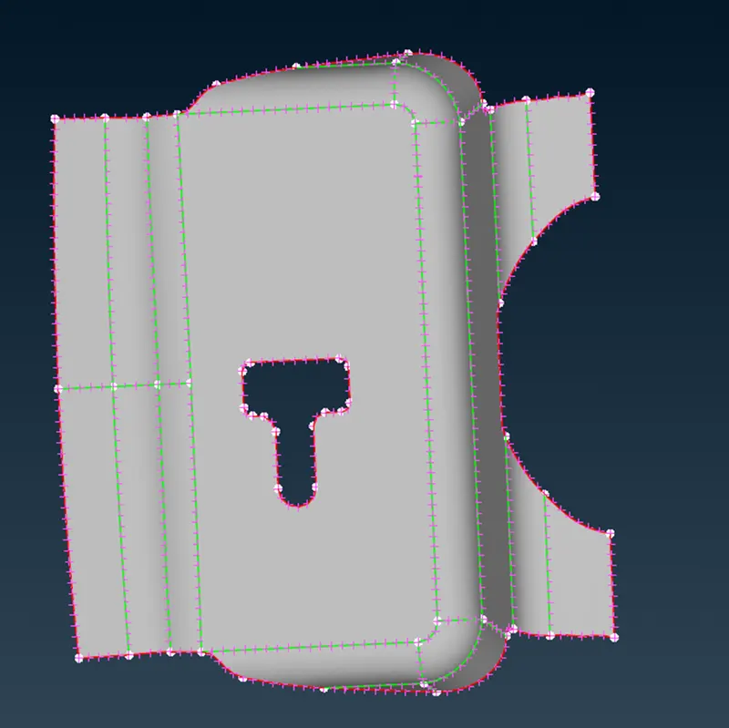
- Use best option for generating shell mesh.
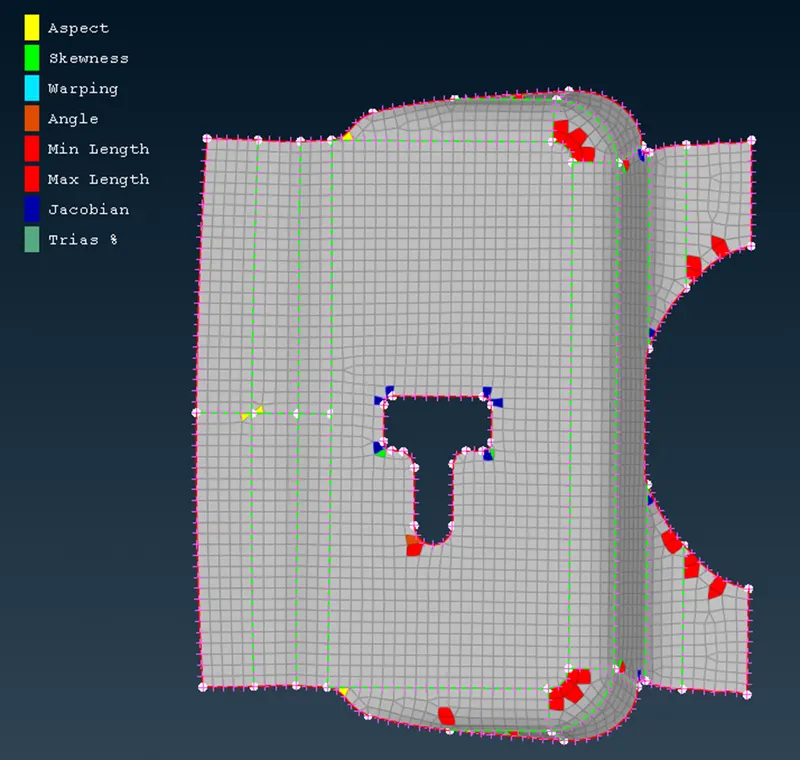
- This is the fnal result.
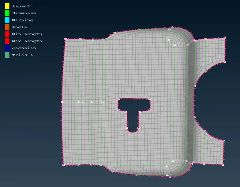
- Continue doing same procedure for all other components.
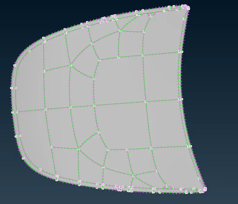
- After geometry cleanup.
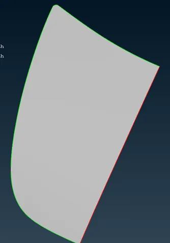
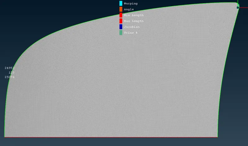
- After complete mesh and before applying symmetrical option.
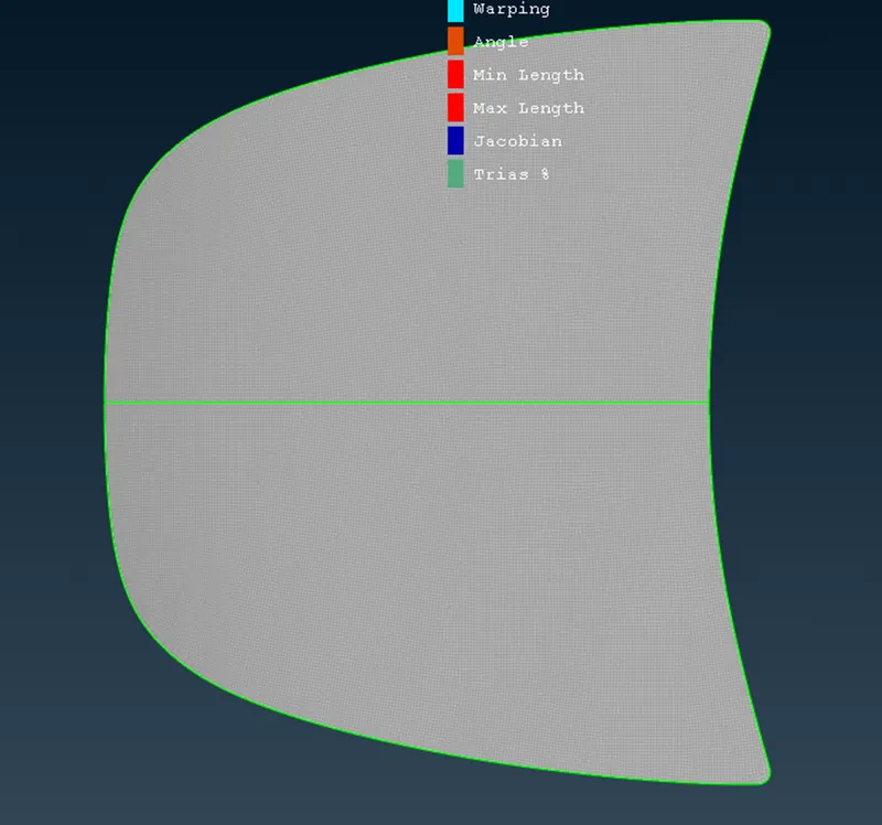
- After symmetricity.
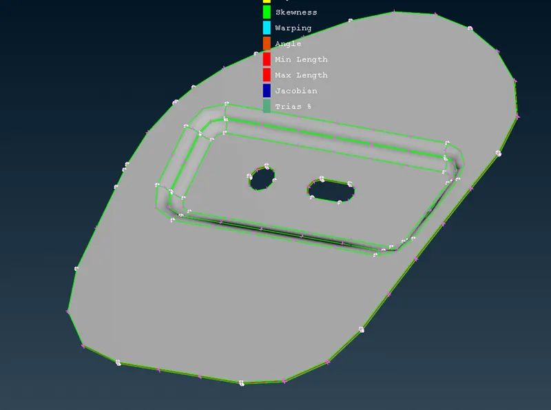
- Same goes for other components.
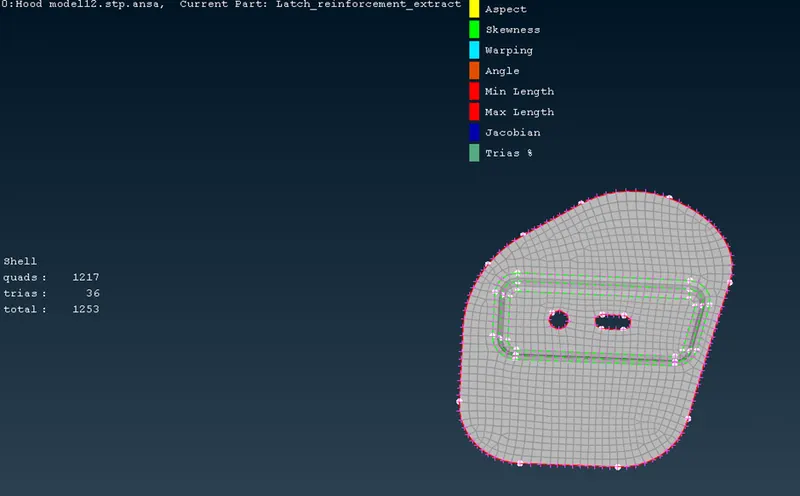
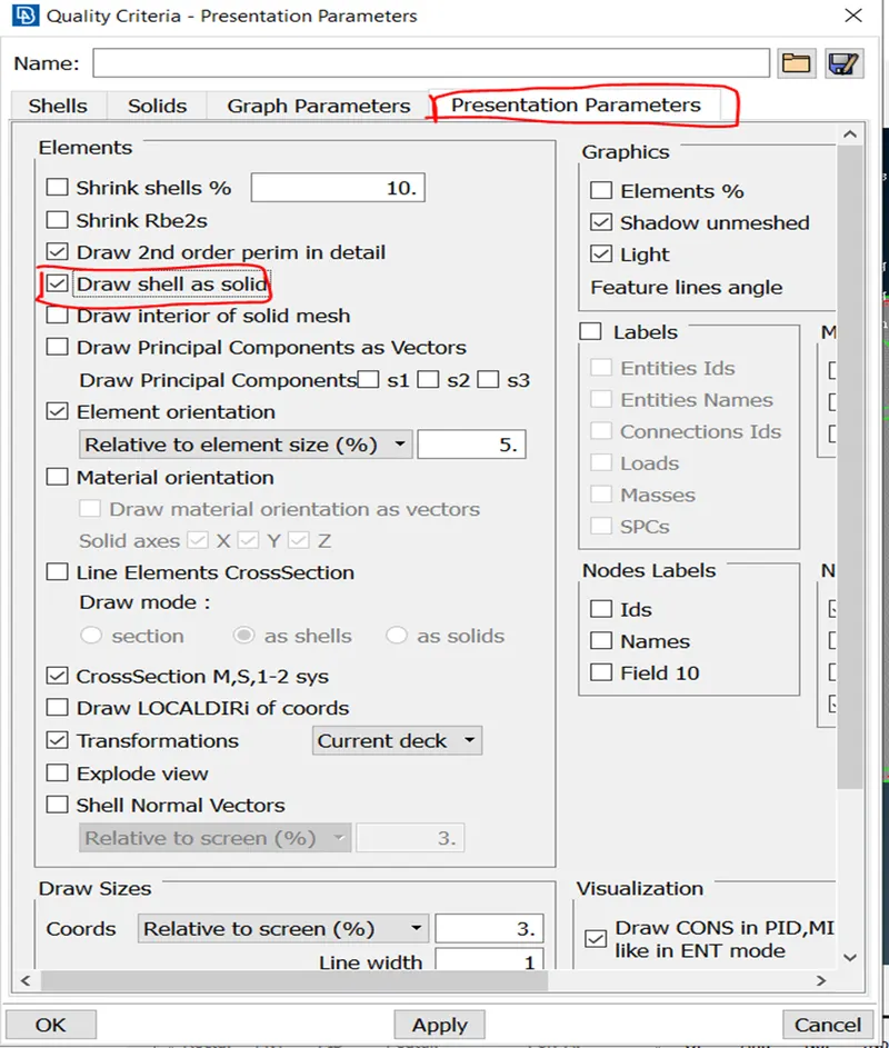
- To visualize the elements in solid form, press F11 and check “draw shell as solid”
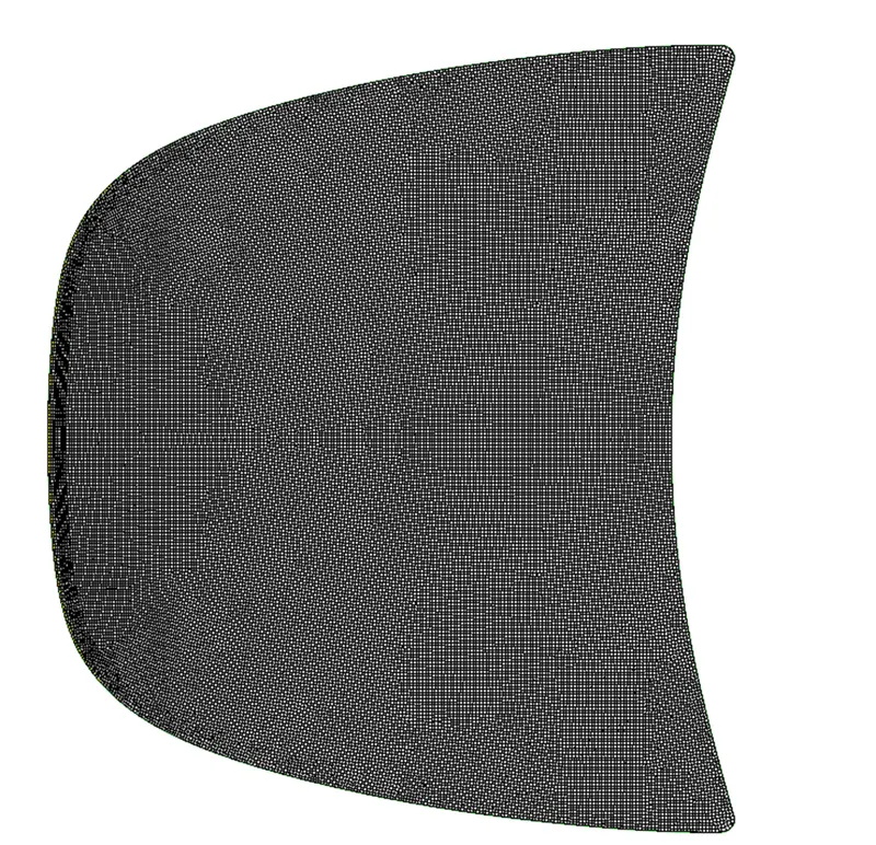
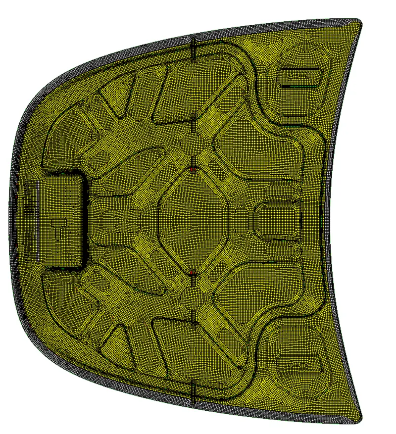
- the final results are:
Conclusion:
- Compared to hyermesh, Ansa gives you better result in shell mesh. There is less work to do.
- Thickness assignment is automatic while extracting mid surface. Of course, there is the option which one has to check for automatic property assignment in option list while extracting mid surface.
- The surface and mesh are connected\attached to each other and mesh is called net or grid. That’s why the full form of ANSA stand as Automatic Net generation for Structural Analysis.
New Things that I learn:
- How to reflect elements, if the geometry is symmetrical. (By using symmetric in transform command)
- While using split command, splitting learn no. of elements in row was tedious task. So, to overcome this, there is an option called “opposite paths” which helps to split quads in a row while selecting opposite edges for quad element.
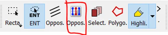
But while using this option, one cannot use right click to shift the tria elements side ways.
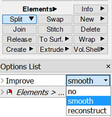
- To automatically smoothen the mesh, while using split command, in option list one can use smooth in improve option.
- How to set PID.