Week 3 - 2D meshing for sheet metal
AIM - 2D Meshing for sheet metal component (Hood).
OBJECTIVE:
- Check for all the geometrical errors.
- Take the midsurface by suitable method.
- Mesh the the midsurface with the given quality criteria.
- All the quality criteria should be satisfied with good mesh flow low percentage of Trias.
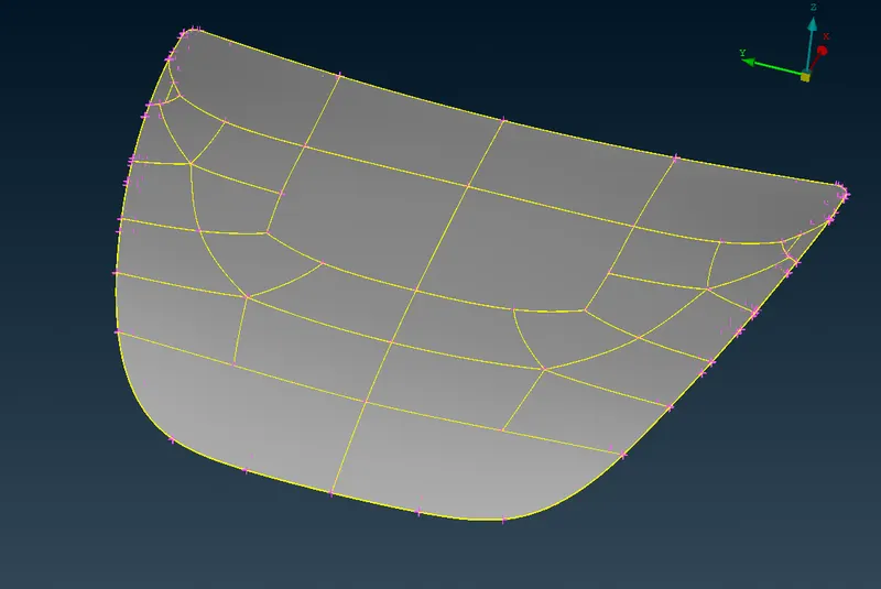
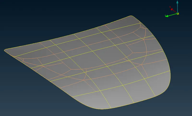
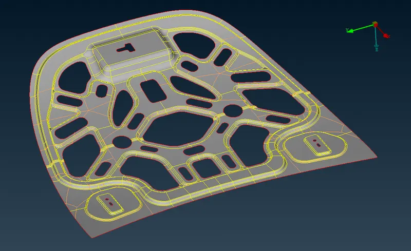
IMAGES BEFORE TOPOLOGY AND GEOMETRY CLEANUP:
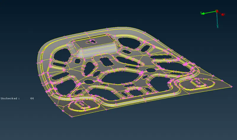
IMAGES AFTER TOPOLOGY AND GEOMETRY CLEANUP:
PROCEDURE:
- At first the model was imported.
- Then geometry cleanup process was done which are discussed below.
- Cons resolution was done by using command Basic mesh → Perimeters → length (Do Box Selection By left mouse click)→ Hit scroll button and in the popup box put Length = 1. The cons of the component get smoother than before.
- Then from the property tab other parts of the hood were hide and one part at a time was choosen to work upon below given parameters.
- Geometry and Topology cleanup.
- Generating midsurface by manual offset method.
- Generating 2D - Mesh.
- Satisfying the quality criteria and achieving a good mesh flow by using split and paste command.
- At first from List → property was selected and part to be worked upon was unhidden rest were hidden. Then from the Module menu Topo was selected and then from faces → Topo was selected to correct any cons error.
- Then From faces → orientation was selected to make the orientation of whole component right.
- After that form Tools tab → checks was selected and geometry check were performed.
- After that midsurface was extracted using offset method by using following command Module → Topo → faces → offset → selected the surface by using feature area selection from pick tab at the botom. Before following the offseting method the thickness was measured for each component part. The original surface was not deleted while offseting the surface.
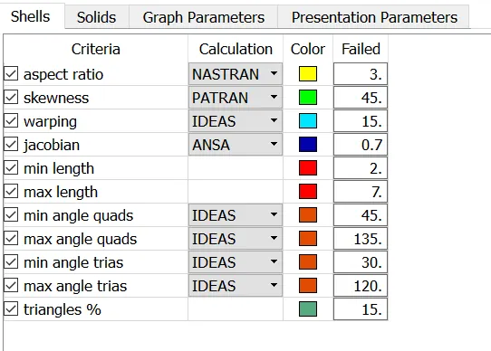
- After that quality parameters and Mesh parameters were set according to the question. The images below shows the same.
QUALITY PARAMETERS:
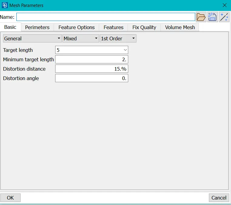
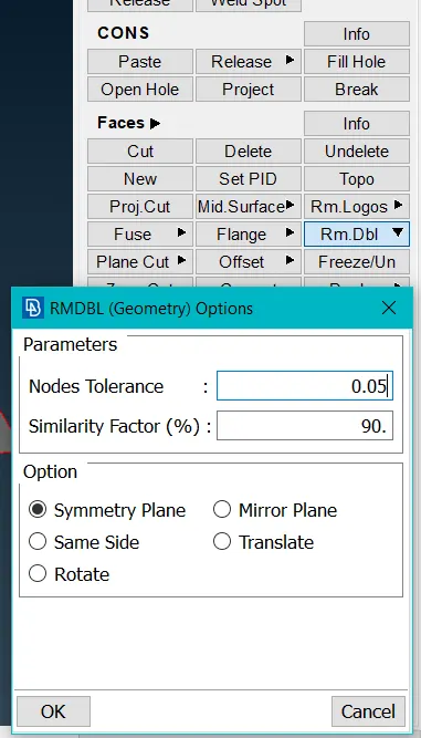
- After setting the Quality and Mesh parameters the components which were symetrical there half surface was deleted to complete the work fast. Command use face → Rm.Dbl. The command help to identify the symmetrical surface and then the surface was deleted manually. Below is the image of the command. This command was use for only two componnets taht is Inner extract of the Hood and the Outer extract of the hood.
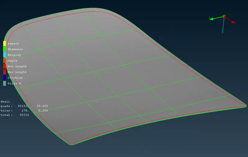
- After that 2D-Meshing was done. For the Outer hood the cons at the edges were modified to avoid the minimum length failure and the surface of outer hood was splitted to control the mesh flow. For 2D-Meshing command use is Module → classic Mesh → Mesh Generation → spot mesh. The to refine the mesh and achieve the quality criteria shell mesh → reconstruct → then improve → then smooth.
- To control flow of trias Split and paste options were used from the Classic mesh panel along with swap and join option
- The trias facing opposite to each other, trias on the features and curve were removed, back to back trias were removed and rotaing quad were avoided.
- All the elements were satisfied for quality.
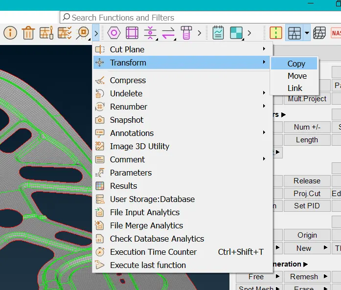
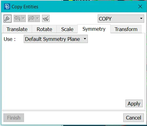
- The form the symmetrical surfaces or part like inner and outer extract of the hood the complete work was reflected using command utilities → transform → copy (select the surface to be reflected and press middle mouse button and select symmetry and press apply and finish). The selected surface is reflected.
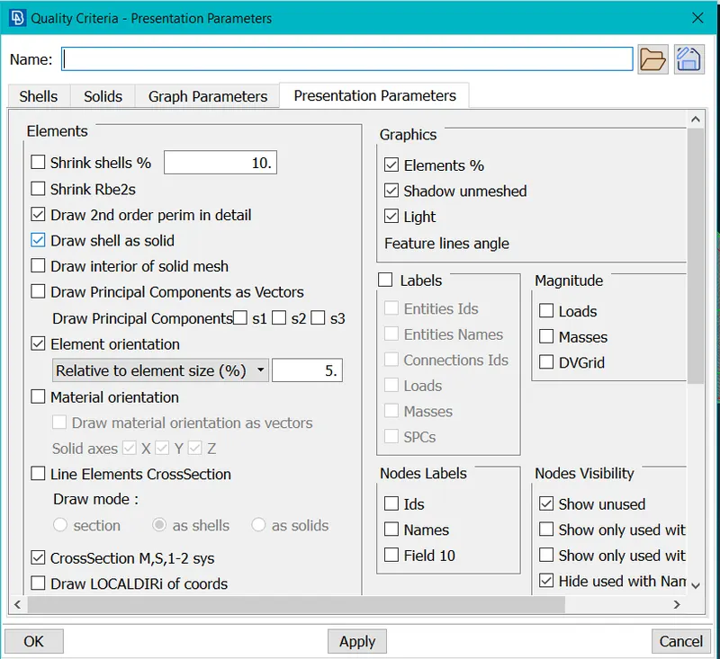
- Then thickness was changed for all th parts as auto property creation created a wrong thickness. After assigning proper thickness Drwa shell as solid was turned on for 3D representation of 2D shell elements to represent the thickness of elements. Below is the image of one part where assigned thickness is visible.
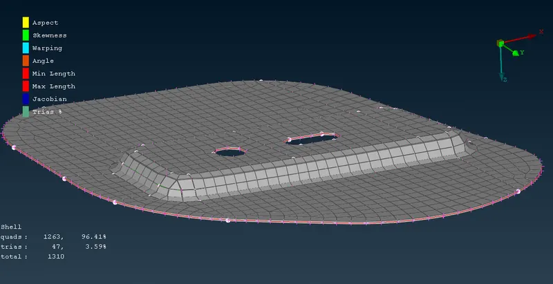
The above process was follwed for all the components parts one by one except the reflection process which was only perform for inner and outer extract of the hood.
LEARNING OUTCOMES:
- Learn How to do topology and geometry cleanup in ANSA software.
- Learn to extract midsurface manually and quicly with efficiency.
- Learned 2D-Meshing. Meshing in ANSA is easier then hypermesh. A good mesh generates for same component for ANSA then in Hypermesh. Satifying the quality criteria is easy in ANSA compare to Hypermesh.
- Learn to assign thickness for 2D-shell elements in ANSA.
- Got Familiar with ANSA GUI.
CONCLUSION:
- The geometry Topology cleanup was done.
- The midsurface was extracted using offset method.
- 2D-Meshing was perform on all the parts of the component.
- All the quality criteria was satisfied 100%.
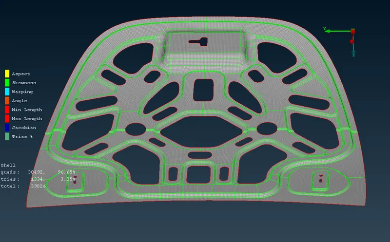
FINAL MODEL IMAGES:
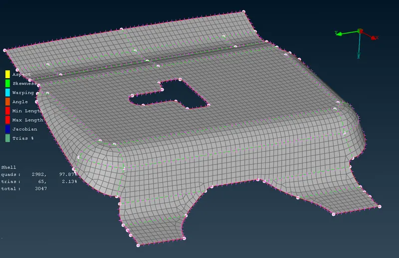
- Outer extract of the hood.
- Inner extract of the hood.
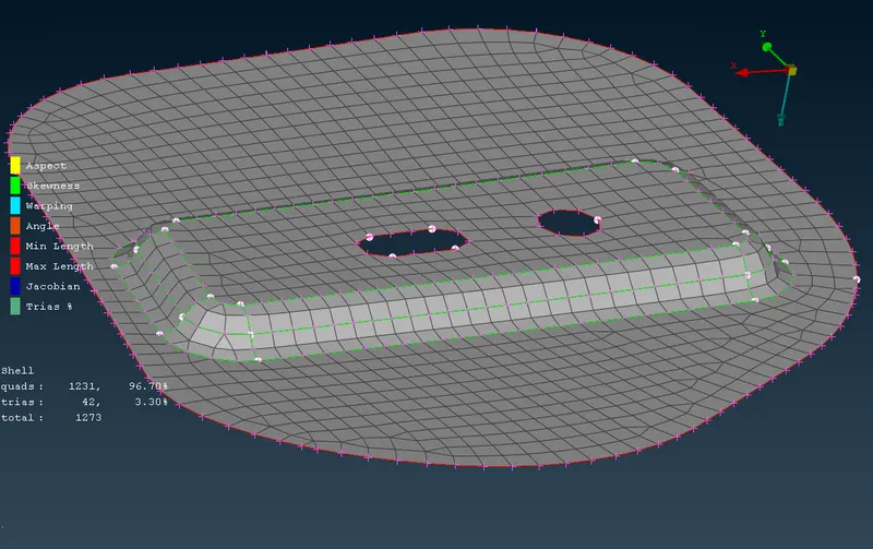
- Latch Reinforcement.