Week 3 - 2D meshing for sheet metal
REPORT ON 2-D MESHING FOR SHEET METAL
AIM:
For the given Hood model, Take the mid surface for all the components after checking the geometrical errors and mesh the mid surface with the given element Quality criteria.
|
S.No |
Quality Criteria |
Value |
|
1 |
Target/Average length |
5 |
|
2 |
Minimum Length |
2 |
|
3 |
Maximum Length |
7 |
|
4 |
Aspect |
3 |
|
5 |
Warpage |
15 |
|
6 |
Skewness |
45 |
|
7 |
Jacobian |
0.7 |
|
8 |
Minimum Quad Angle |
45 |
|
9 |
Maximum Quad Angle |
135 |
|
10 |
Minimum Tria Angle |
30 |
|
11 |
Maximum Tria Angle |
120 |
|
10 |
Tria Percentage |
15 |
INTRODUCTION:
The car's hood is given for the operation. The car's hood is simply a sheet metal component. The geometry of this hood model is taken into consideration in the ANSA interface inorder to establish proper mesh andd check quality criterias.The car's hood is composed of 4 different parts.
- Outer panel
- Inner panel
- Latch
- Hinges
METHODOLOGY:
1.Import:-
- File > Open > Choose the File and hit on open.
2.Cons resolution by Length option in Mesh module.
- If the imported file is an .igs file it doesn’t have any connectivity between the Surfaces.
- To get the connectivity between the surfaces we have to use the Topo option.(TOPO Module> Faces > Topo)
- We have to Orient the Surfaces to make sure all the surfaces are in one normal direction.(TOPO Module> Faces > Orient)
3.Checking the geometrical errors.
4.Clearing the geometry errors.
5.Check the thickness of the components.
- If the thickness is less than 5 or 6mm then we have to extract the midsurface.
- If the thickness is more than 5 or 6mm then no need to extract the midsurface.
- Creating the midsurface for a sheet metal Component.
- If the components have the uniform thickness then we will be using the Skin or Offset options to extract the midsurface.
- If we are using the skin method make sure that unchecking of Delete original surfaces in the options list.
- If we are using the Offset option, we will be using the feature selection to get the mid surface in an easier manner. While providing the offset value we have to make a change in the options list from use existing to auto create for the property.
7.Providing the Target element length by using the length option in the mesh module.
8.Providing the Mesh Parameters and Quality criteria to the models.
9.Cleaning the Midsurface extracted.
- If there are any unnecessary hotpoints we will be using the Delete option in Hotpoints group to avoid or we can use the insert option with right mouse click.
- If there are any construction lines which will affect the mesh flow we will avoid them.
- If there are any two feature lines which are very near to each other and the distance between them is less than your minimum then you will be suppressing any one of the line.
- Feature Line:- We call a double con as a feature line when the surface after that double has significance change(Flat surface may be attached to a curved surface or viceversa) in the geometry.
10.Spliting the surface in the small square-like structures.
11.Generating the Mesh.
12.Clear the elements which are failing for the quality criteria.
13.Assign the proper orientation to the elements.
14. Assign the proper thickness for the newly created midsurface.
15. Release the FE from the Geometry.
PROCEDURES:
1. The hood model which is the CAD geometry is imported to ANSA workspace. The model includes 4 components.
- Outer Extract
- Inner Extract
- Hinge
- Latch
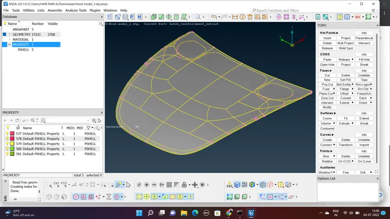
In the ANSA interface, we are visible with many options which we are using to do the mesh and preceding procedures. Also the database area shows the geometry, properties present in the uploaded model.
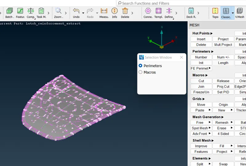
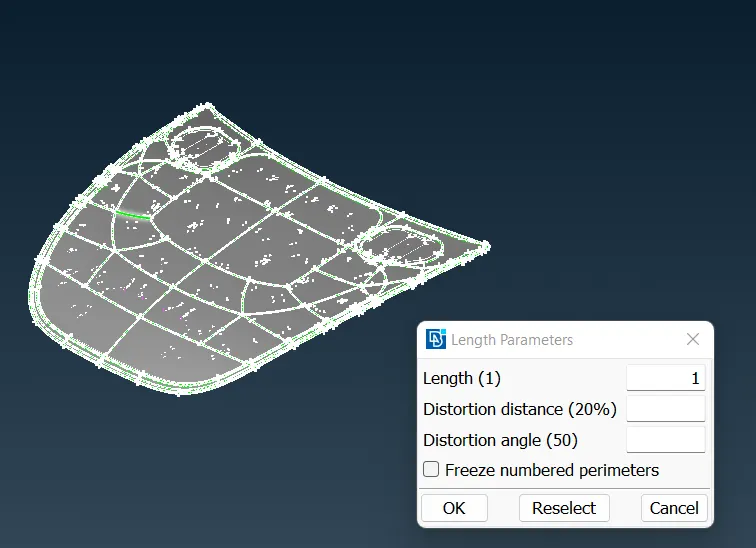
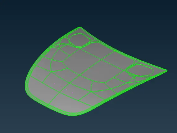
2. The holes and edges may be not properly alinged. So the cons resolution can be set up to 1mm. Therefore the holes edges everything are well aligned and visible.
So this can be done by selecting Classic mesh> Perimeter > Length.
The con resolution is turned to 1mm for both perimeter and macros .
3. The next step to do is the geometry check for the model. This can be done by Tools > Check > Geometry.
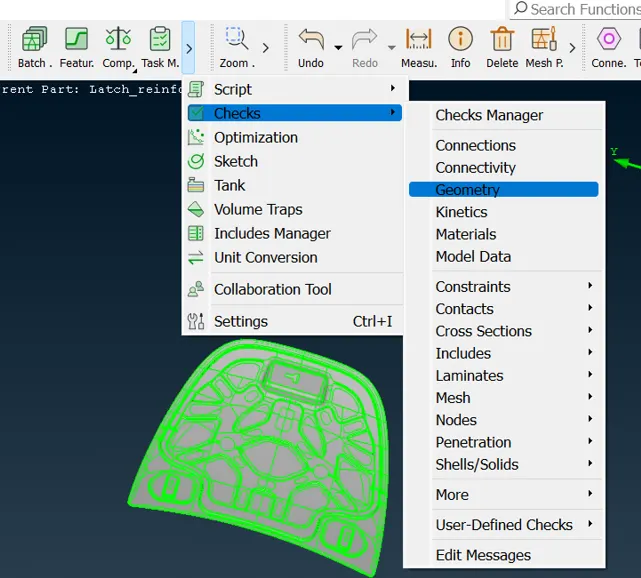
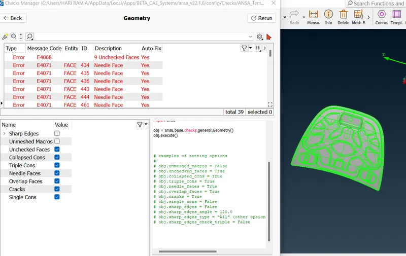
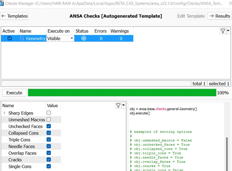
The errors can be autofix by selecting all errors. For this model, all the errors get autofixed. Later to check for clarity, again checking geometry. The errors are autofixed. So, the check will be shown a tck in the status area.
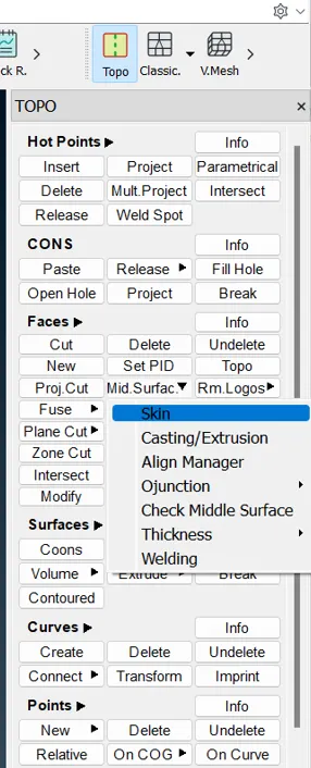
4. The next step is to extract the midsurface for each components. There are multiple methods to do the mid surfacing. Here the skin midsurfacing is used. This option is visible in the topo module. Topo module> Faces > Mid surfacing > Skin.
Before jumping on to mid surfacing it is good to go for individual component geometry check up. The thickness of the components should be checked in few areas inorder to determine that whether same thickness is present in every area.To check the thickness select measure tab from the utility area and measure the thickess for some areas. If it is less than 5 mm we go for 2D meshing and if it is greater than 5 or 6mm then go for 3D meshing.
The thickness can be measured as hsown below.
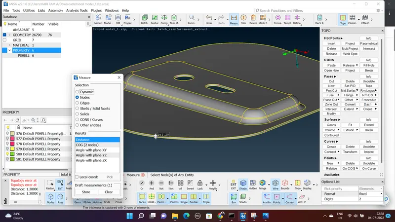
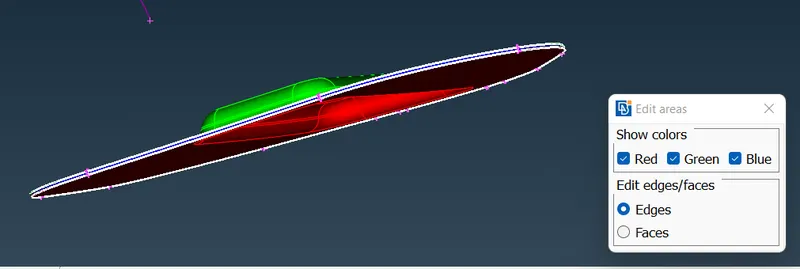
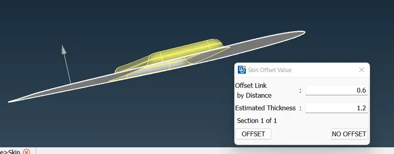
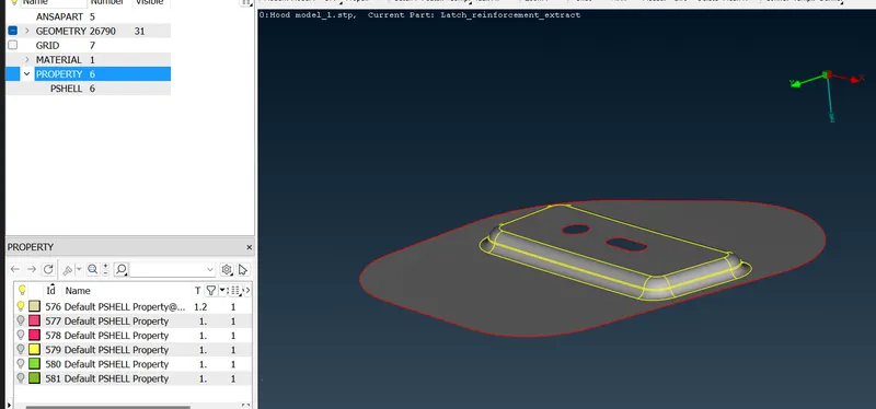
It is visible from the screensho that while extracting mid surface using skin method, the offset value is to be auto determmined in skin midsurfacing method. This is not the case in offset method. We have to give the offset value manually by viewing the normal arrow. The mid surface which is generated by skin mid surfacing is automatically assigned to new PID as visible in the screenshots.The components which are mid surfaced are shown below.
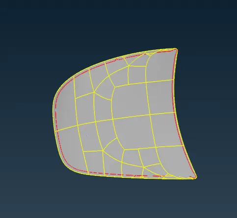
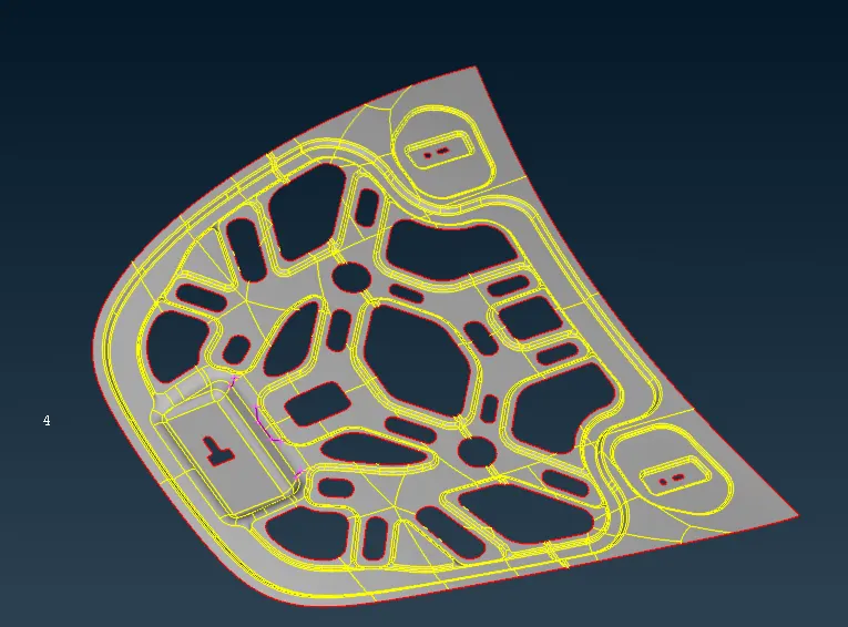
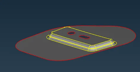
5. After mid surfacing, the next step is to do the geometric cleanup. ie, removing or suppressing the unwanted construction lines present in the model during design. Such cons will affect the meshing severely. So it is better to suppress using Topo module> Faces > Cut and then right click on the construction lines which are to be suppressed.
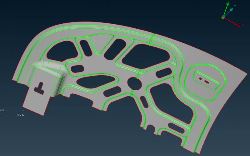
It is the Outer panel of hood after midsurfacing. We can see many construction lines in the surfaces. Inorder to suppress and make a geometry cleanup to make the mesh we are suppressing those construction lines.The features lines which describes the curves and shape of the edges are not to be suppressed. If it is suppressed it will affect the mesh flow. The ultimate aim of geometric cleanup is to develop a geometry to obtain a better mesh flow.The second image shows the model after geometric cleanup. The sharp edges, mutiple cons, construction lines should be removed in this process.
The construction lines can be suppressed by right clicking on the line after selectiong topo> faces > cut Or Classic Mesh> Macros > Cut.
To release the con, Topo > Cons > Release. Do the topo if required after releasing the cons.
6. The meshing of the model is the next step. Meshing should be done to determine the mesh flow. For any model, the mesh flow should be better.In our model, we are doing 2D meshing. There are tra, quad, tetra, hexa elements present.
Operations to obtain proper mesh flow:
Split: Split is used to split the shell and solid elements into smaller by selecting element edges and nodes.
Swap: It rotates the common edge of two shells.
Paste : It is used for manual/ automatic pasting of nodes.
Best mesh : It is the type of mesh which mesh macros using all alternative algorithm and keep only the mesh of best quality.
Reconstruction : It is used to reconstruct the mesh in FEM and macro areas.
Smooth : This option helps to smooth the mesh on selected macro areas or FEM.
Improve : This helps to improve the existing mesh.
Cut : It cuts a macro area with 2 perimeter nodes or hot points.
Join: This is used to join macro areas.
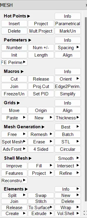
The quality criterias are to be given for the respective model as per the objective. The quality criterias is essential to undertsand the areas the mesh elements are failing. Thus the meshing can be improved by the tools.
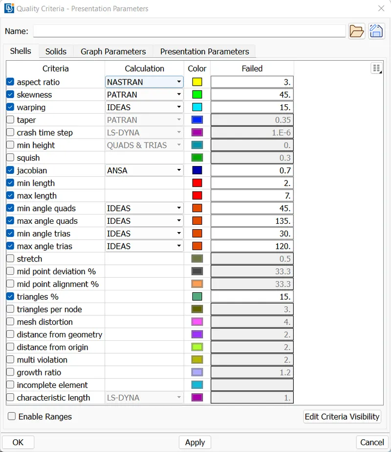
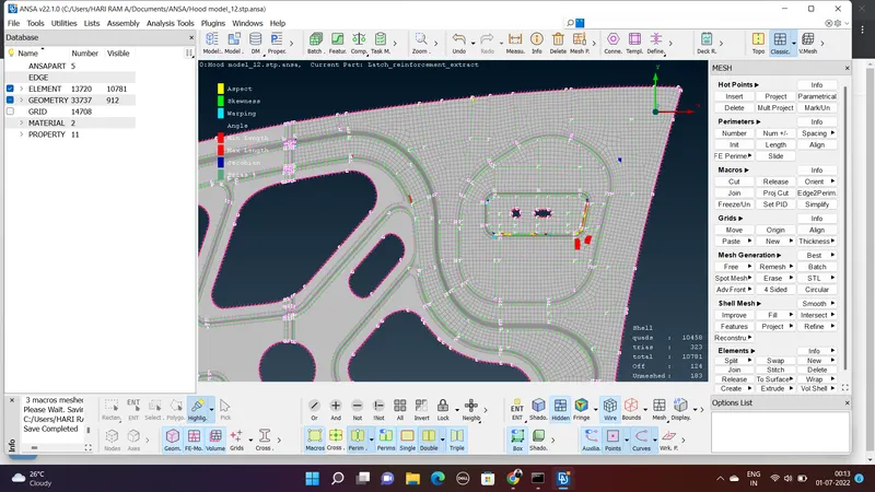
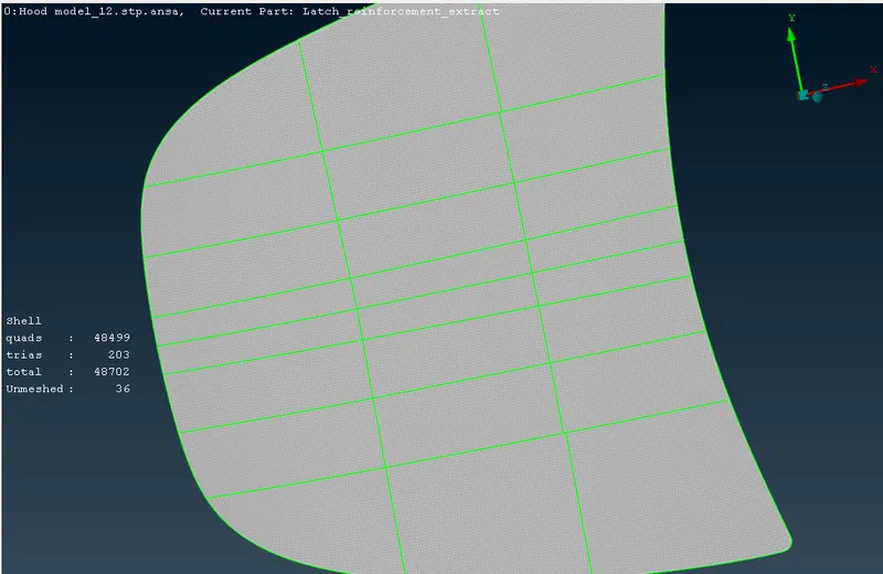
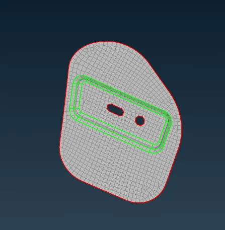
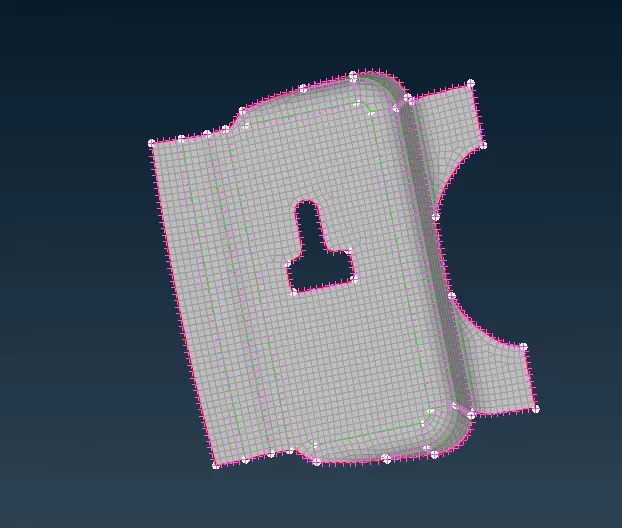
The quality criterias should be applied to the models which are subjected to meshing. Thus the meshed elements will be shown some failing due to inappropriate mesh elements. The mesh flow can be improved by removing opposite tria elements, rotational quad elements etc. The meshing element and the improved mesh can be shown below .
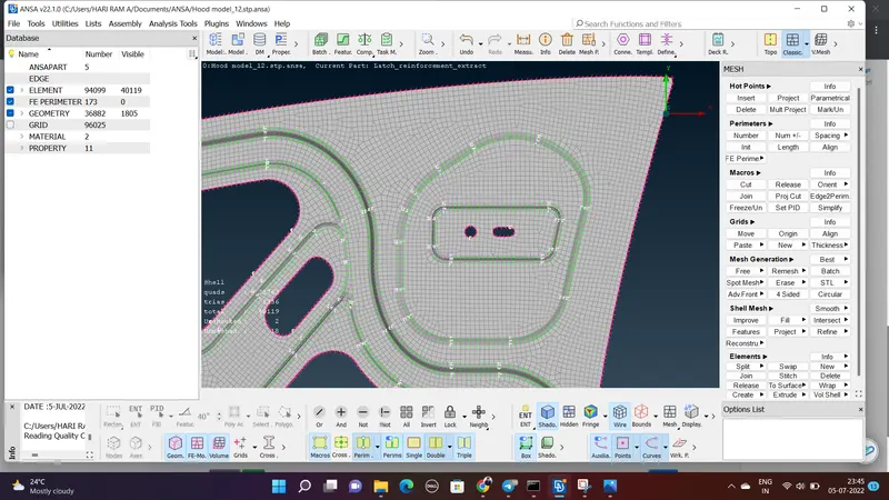
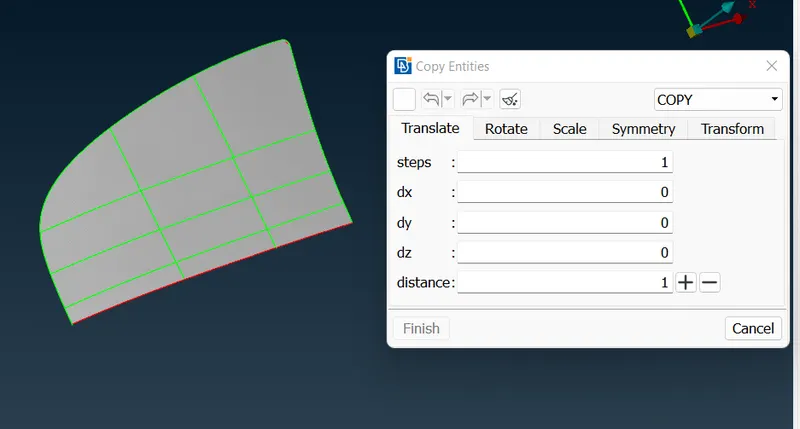
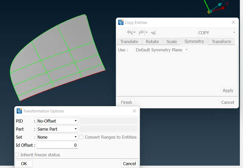
To resolve time loss, the meshing can be done for the inner panel and outer panel in a proper way. There are symmetrical portions in inner and outer panel components. Initailly the symmetrical half of the components are deleted and after meshing the half it is transformed by using symmetry option. This can be done as Utilities > Transform.
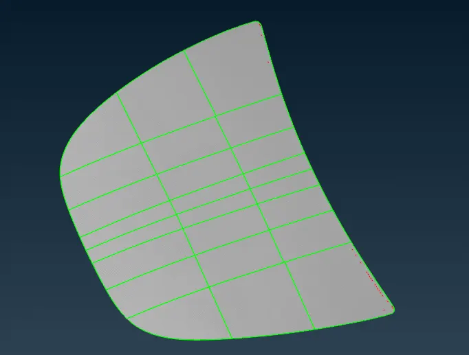
The meshed elements with better mesh flow are shown below.
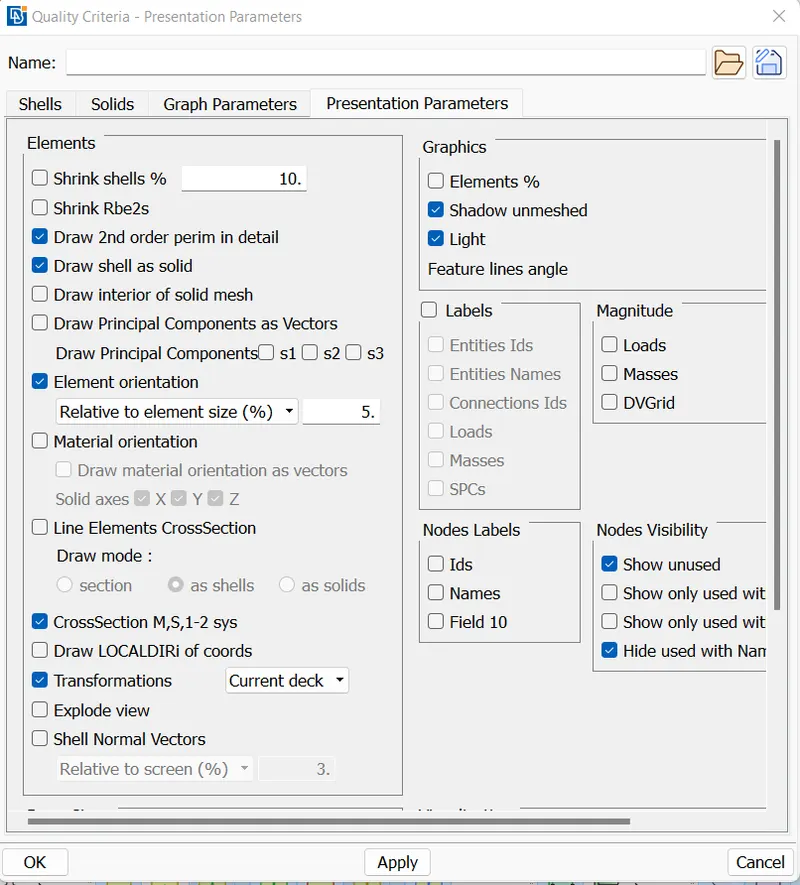
7. The last step is to provide draw shell as solid option to get the appropriate thickness. This can be done as follows.
Quality Criteria > Presentation parameter > Draw shell as solid
LEARNING OUTCOMES:
By performing mesh for sheet metal component, it provides the ideas and measures that should be taken into account. The learning outcomes from this meshing are as follows.
- Understand how to do the geometric checks and correct the errors happening in the check.
- Identify the thickness of the component and extract the midsurfacing by various methods.
- Providing quality criteria to the model and based on it visualise the model.
- To mesh the components to obtain a proper mesh flow using mesh elements.
This helps to get an overall undertsanding on how to perform the mesh in a sheet metal component.
CONCLUSION:
The hood model mid surface got extracted and meshed the components with proper mesh flow.
Google Drive Link: https://drive.google.com/file/d/1T5zqpiaOV7BDzSP9-kcN2Omhx4VozW__/view?usp=sharing