Week 3 - 2D meshing for sheet metal
AIM
For the given Hood model, Take the mid surface for all the components after checking the geometrical errors and mesh the mid surface with the given element Quality criteria.
INTRODUCTION
COMPUTER AIDED ENGINEERING (CAE)
Computer-aided engineering (CAE) is the use of computer software to simulate performance in order to improve product designs or assist in the resolution of engineering problems for a wide range of industries. This includes simulation, validation and optimization of products, processes, and manufacturing tools.
A typical CAE process comprises of preprocessing, solving, and postprocessing steps. In the preprocessing phase, engineers model
the geometry (or a system representation) and the physical properties of the design, as well as the environment in the form of applied loads or constraints. Next, the model is solved using an appropriate mathematical formulation of the underlying physics. In the post-processing phase, the results are presented to the engineer for review.
ANSA
ANSA - Stands for Automatic net generation for stuctural analysis. ANSA is an advanced multidisciplinary CAE pre-processing tool that provides all the necessary functionality for full-model build up, from CAD data to ready-to-run solver input file, in a single integrated environment.
ANSA is the users’ preference due to its wide range of features and tools that meet their needs. The list of productive and versatile features is long and the alternative tasks and processes to be completed using them are countless.
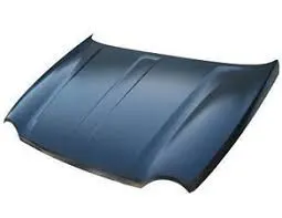
On front-engined cars, the hood may be hinged at either the front or the rear edge, or in earlier models (e.g. the Ford Model T) it may be split into two sections, one on each side, each hinged along the centerline. A further variant combines the bonnet and wheel arches into one section and allows the entire front bodywork to tilt forwards around a pivot near the front of the vehicle.
Hoods are usually made from the same material as the rest of the body. This can be steel, aluminum, fiberglass, or carbon fiber. However, some aftermarket companies produce fiberglass or carbon fiber steel hood replacements to make the vehicle lighter.
The hood release system is common on most vehicles and typically consists of an inner hood latch/lock handle, a hood release cable, and a hood lock assembly. The hood lock handle is usually located under the steering wheel, next to the driver’s seat, or in the door frame.
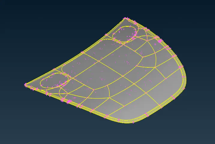
- Open the hood model from the files and it must be carried out for several operations .
- Check the geometry of the model from the 'checks' and execute the operation by selecting required check parameters .
- Fix the geometry manualy or by means of auto fix (geometry clean up ) .
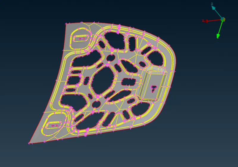
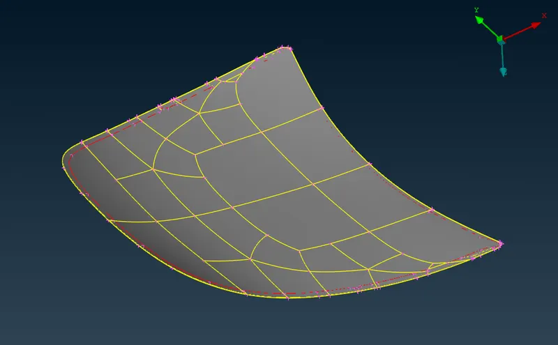
We are provide with a hood containing 5 properties or components.
- After geometric clean up , we have to perform 'MID SURFACING' for each property .
- Mid surfacing can be done manualy by offset method or automaticaly .
- Measure the thickness of the component by measure command .
From TOPO ----> Faces --> Offset ( enabling the feature area ON in 40 degree ) select any face of the model , ensure that the other face is not selected .
After selecting the face we are supposed to provide the offset length ( thickness/2) and sign regarding offset direction (+ or - ).
The offseted surface needs to be extracted in order to perform meshing , for this
select 'Not' ( for hiding the selected entities ) and turning ON 'PID' then select the non mid surface and entering by middle clicking .
OR
select ' !Not ' ( to keep only the selected entities ) and turning ON the 'PID' , then select the mid surface and enter .
The neighbouring surfaces can be finded by using " And ".
MID-SURFACED COMPONENTS
1
2
3
4
- A proper or given quality parameter criteria must be provided for the components by clicking F11 .
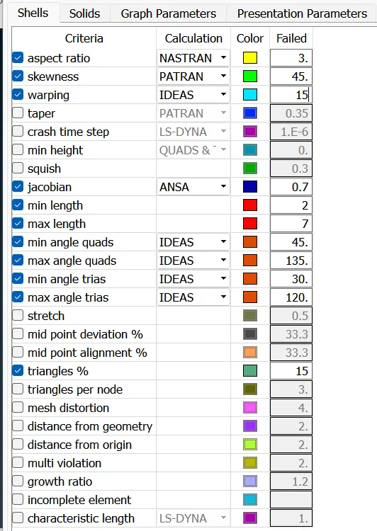
- Go to presentation parameter and turn ON the elements % .
- After the Mid surfacing and setting quality parameters, the meshing needs to be performed .
- For meshing a proper mesh parameters should be given .
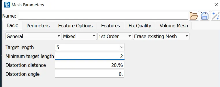
- Give proper Topo for the property ,and set a average length using perimeters in classic mesh option .
- Perform Fine for a perfect edges and actual design .
- Remove un wanted hotpoints from the components using delete/insert option in hotpoint option from TOPO.
- Check for minimum length and if founded supress it using cut in faces at topo .
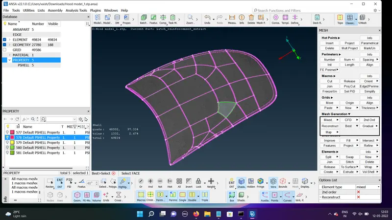
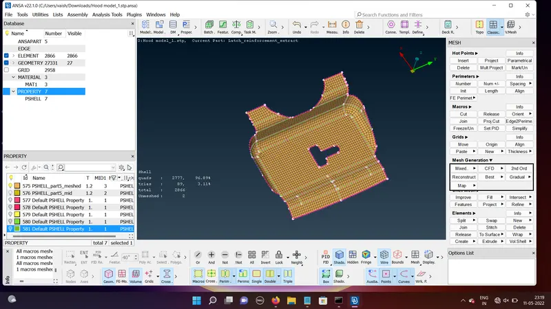
- For performing mesh select classic mesh and go for mesh generation and select best .
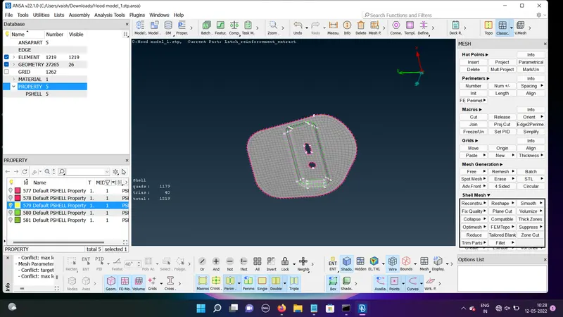
- Modify or make the the mesh perfect by using smooth,reconstruct,split commands .
- Remove the trias from the edges for perfect meshing .
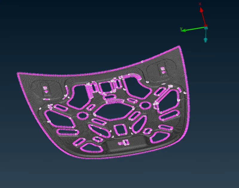
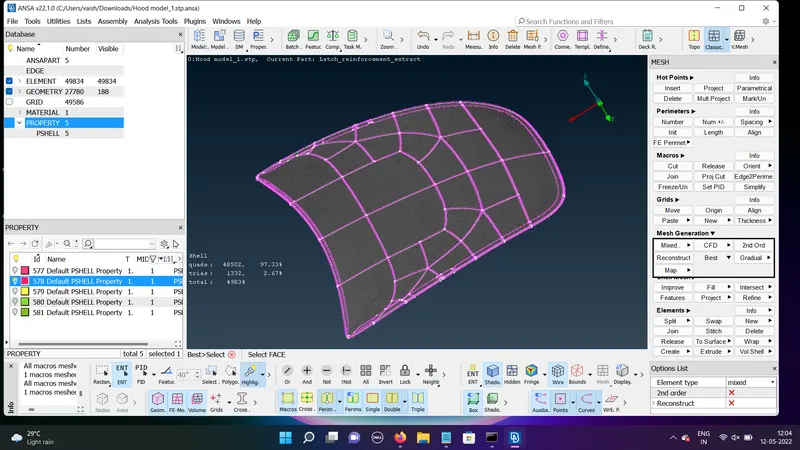
- Perform proper and good assigned mesh in all the components .
MESHED IMAGES
LEARNING OUTCOMES
- For performing geometric clean up ,
geometry - execute - finding - fixing manualy/ auto fix
2.for Mid surfacing ,
Topo - faces - offset -select face-enter offset value/direction- ok
3.for mid surface extraction,
!Not - turn on PID - select the mid plane - enter
OR
Not - turn on PID - Select any thickness face - enter
4.for getting neighbouring elements
And - select - enter
5.for deleting hot points ,
hotpoint - insert/delete
6.for deleting un wanted lines ,
topo - faces - cut -select - right click
7.for making the design good,
topo - auxilleries - fine - enter
8.for removing triple cons ,
topo - CONS - release - enter
9. for joining two single cones,
faces -topo - select separate
10.for making mesh improved ,
classic mesh - shell mesh - smooth / reconstruct
11.for changing trias position
classic mesh - element - split
classic mesh - grids - paste
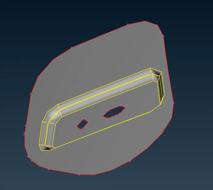
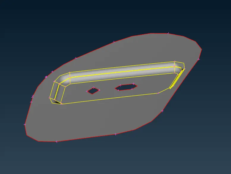
In order to solve this Min length error, One can toggle (suppress) the top and bottom double cons at the fillet region of a mid surface (Toggled cons will be represented as Orange colour lines). This is called ‘defeaturing’ the midsurface.
CONCLUSION
Performed geometric clean up , mid-surface generation,shell meshing and element quality check on the given hoods model of an automobile by using ANSA preprocessor .