Week 3 - 2D meshing for sheet metal
Objective:
The objective of this project is to perform preprocessingie. geometry cleanup, mid surface extraction, and 2D shell meshing for the hood componentof a car. After meshing, component thickness and material need to be assigned to the mesh. And the mesh should follow the following quality criteria,
S.no. Quality criteria Value
1 Target/Average length 5
2 Minimum Length 2
3 Maximum Length 7
4 Aspect 3
5 Warpage 15
6 SkewneSs 45
7 Jacobian 0.7
8 Minimum Quad Angle 45
9 Maximum Quad Angle 135
10 Minimum Tria Angle 30
11 Maximum Tria Angle 120
12 Tria Percentage 15
Procedure:
First, the hood model is imported into the ANSA. The hood model contains five individual components as shown below:
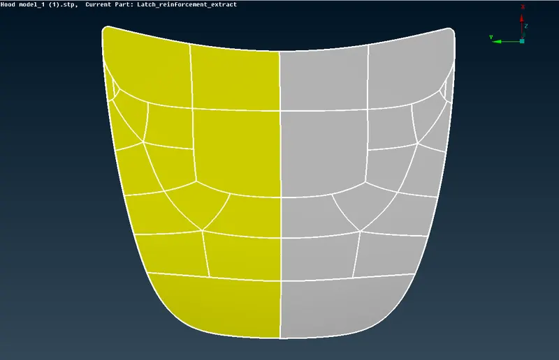
1. Outer of Hood
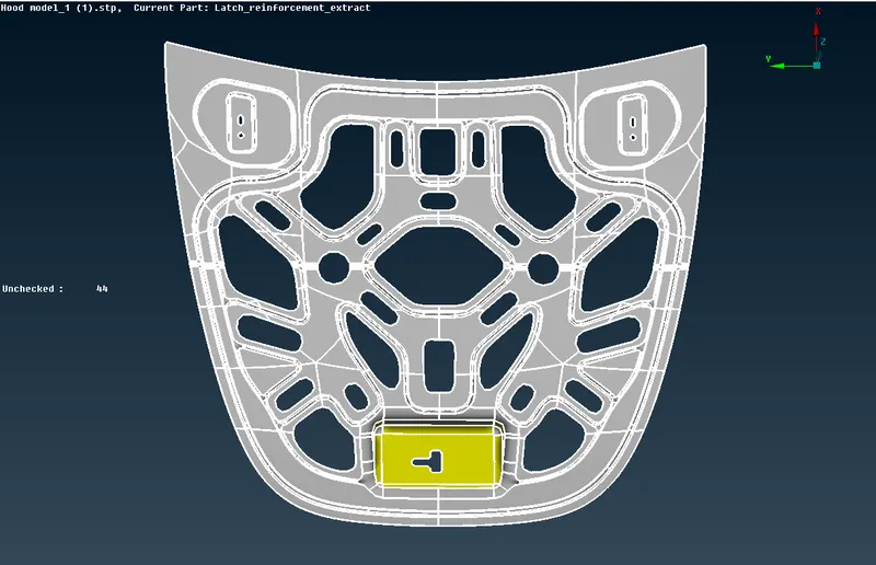
2. Inner of Hood
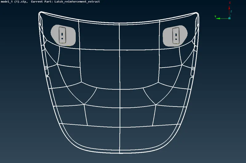
3.Hinges of Hood
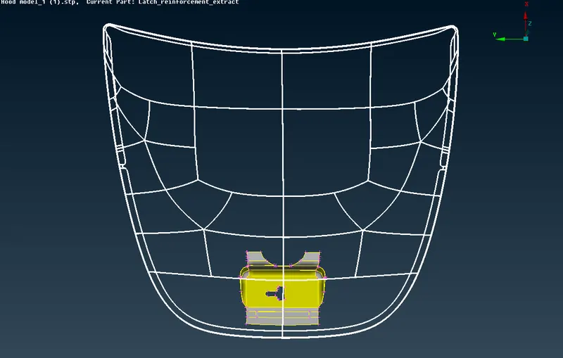
4.Lock of Hood
We need to lock the each of that part seperatly of making our work easy and effectivily. And here we lock to four parts , the two hinges are locked together.
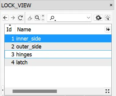
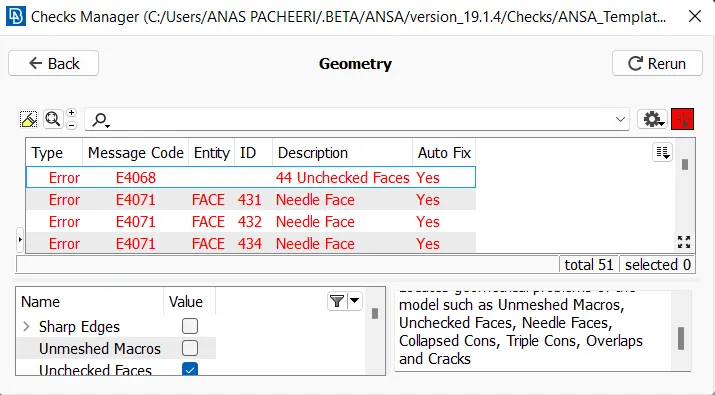
The first step after importing the model is to properly analyze and understand the geometry. When a CAD model is imported into the ANSA, there might be several geometrical errors like missing/distorted surfaces, intersecting surfaces, etc. due to the format conversion process or inherent bad model. And, it is important to clear all these errors before starting meshing. So, the next step is to clean up the geometry. To ensure that all the surfaces are connected properly Faces> Topo tool is used for all the edges of each individual component at a time. Next, geometry check is performed by going to Checks>Geometry and running it for parameters as shown in the image below. Another image shows the errors detected.
Most of the errors were fixed automatically by right-clicking on the error>fix.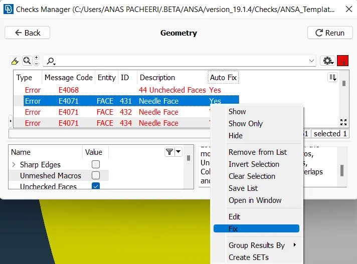
Next, the orientation of all the faces is modified by going to Faces>Orient. This ensures that all faces are oriented similarly.The next, step is to extract the mid surfaces for each component and keep them in separate property id. Midsurfaces are extracted using the manual method i.e. offsetting the surfaces of either face to the middle. First, the thickness of each component is measured using the Measure tool from Utilities>Measure.
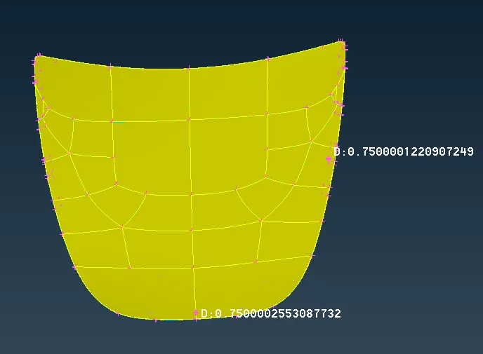
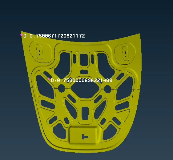
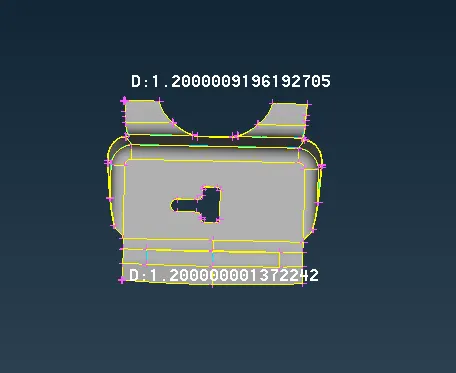
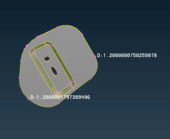
The outer panel and inner panel were found to be 0.75mm thick and the latch and hinges were found to be 1.2mm. As they are sheet metal components, the thickness is uniform across the component. Then, four properties are created by going to List>Properties>New. Thickness is assigned to each property and a Material 'Steel' is also created and assigned to each property.
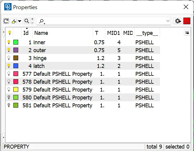
Next, the mid surface is extracted using the Offset tool by going to Faces>Offset and selecting all the surfaces on one face. Then, half of the thickness is given as the offset value, the direction is checked and offset. Now, the property is assigned to the extracted mid surface by going to Faces>Set PID and assigning to the respective property. Similarly, all mid surfaces are extracted and property assigned for all the components.
After we have done the Offset we can see that our models edges are not much good so we can have the help of the fine tools help which present in the Axuiliaries and select the fine and click on the points we want to clear.
Next, mesh parameters are configured b·y going to Utilities>Mesh Parameters. There, target length, minimum element length, and maximum element length are configured to 5, 2, & 7, respectively. All other parameters are kept as default for mixed and 1st order elements.
Next, quality criteria are configured by going to Utilities>Quality Criteria. And, the quality criteria file is saved for future reference. The created quality criteria parame·ters are shown in the image below.
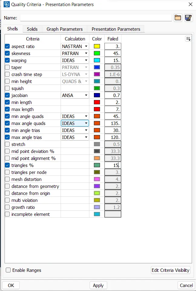
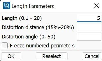
The next step is to prepare the mid surfaces for meshing. For that, switch to the Mesh module. First, the shell element length is altered by going to Perimeters>Length and all the CONS are selected and target element length 5 is fed as length value. The same is done for all the Macros (surfaces).
Next, all the areas are checked for minimum element length and altered where elements might fail for minimum length. Similarly, CONS which are not essential to define a feature are removed by joining the surfaces using the Macros>}oin tool. Also, the complete mid surface model is divided strategically into sections using Macros>Cut and Macros>Project Cut tool. This will help to generate a better quality mesh. Also, all the holes are rotated using the Perimeters>Slide tool to ensure the CONS are parallel to the nearby CON. This will help in generating a mesh with good flow. The result of the above steps is shown in the image below. The same process is repeated for all the mid surface components.
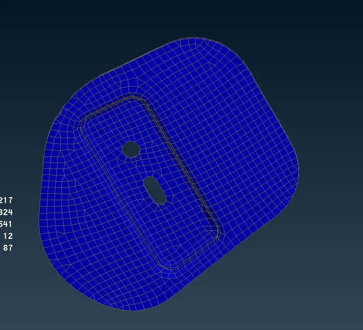
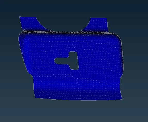
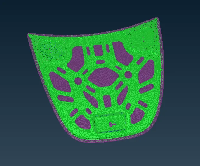
Next, meshing is done using the Mesh generation>Best tool. This tool generates the mesh using the best algorithm applicable. Then, the created mesh is refined using the Shell Mesh>Reconstruct tool. It is ensured that there are no rotating quads. Also, trias are kept as low as possible. After modifying the mesh, Shell Mesh>Smooth tool is used to smoothen the flow of the mesh. Any elements failing for quality criteria are also fixed by either remeshing or smoothing the elements. The created mesh is shown below,
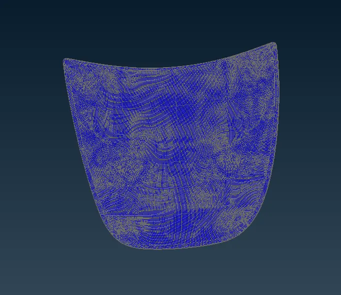
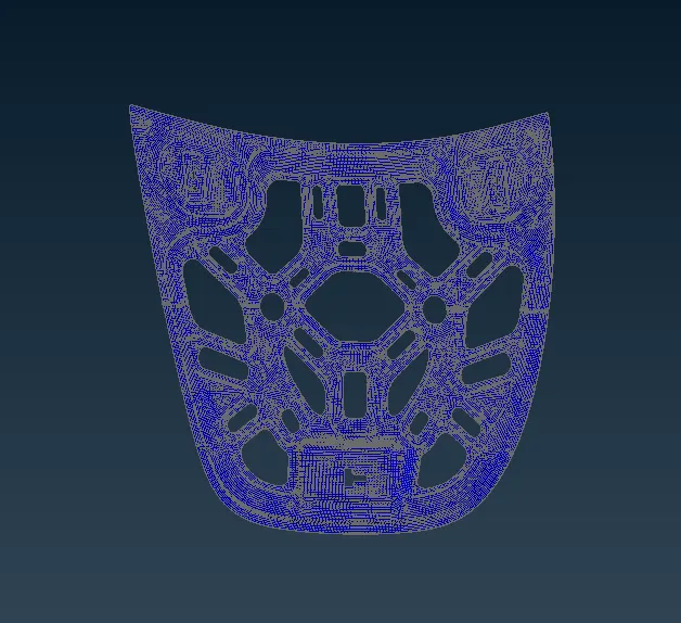
The working model after doing all the above are represnt below in the link :
https://drive.google.com/file/d/1CyQ5MNQlOCXTZWkjZtsIaT1iN0t25but/view?usp=sharing