Week 3 - 2D meshing for sheet metal
WEEK 3 : 2D MESHING FOR SHEET METAL
AIM: To create a midsurface and mesh the given sheet metal Hood model. The mesh should satisfy the given quality criteria.
|
S.No |
Quality Criteria |
Value |
|
1 |
Target/Average length |
5 |
|
2 |
Minimum Length |
2 |
|
3 |
Maximum Length |
7 |
|
4 |
Aspect |
3 |
|
5 |
Warpage |
15 |
|
6 |
Skewness |
45 |
|
7 |
Jacobian |
0.7 |
|
8 |
Minimum Quad Angle |
45 |
|
9 |
Maximum Quad Angle |
135 |
|
10 |
Minimum Tria Angle |
30 |
|
11 |
Maximum Tria Angle |
120 |
|
10 |
Tria Percentage |
15 |
PROCEDURE:
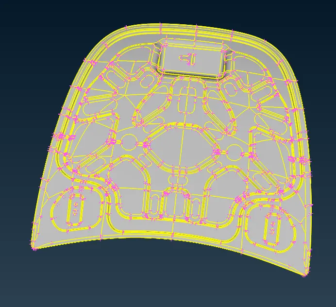
1) Import the given stp file in ansa. The imported file has vehicle hood assembly consisting of 4 parts.
2) Check the geometry before creating a midsurface for each component. Geometry check is carried by selecting Tools>Checks>Geometry.
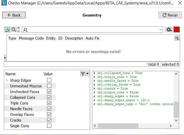
3) After checking if any errors are found then fix it by selecting Actions>Fix. If still the geometry check fails then use topo tool rectify the error.
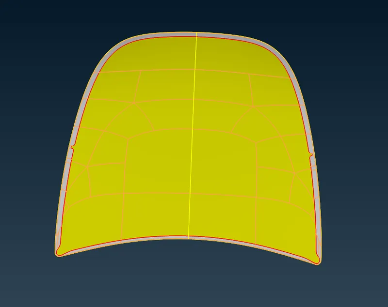
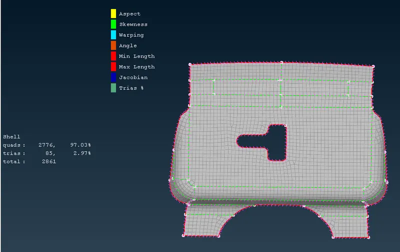
4) Then to create a midsurface select we use auto midsurface tool; Topo>Faces>Midsurface. The below image is of outer_extract component. Similarly, midsurfaces are also created.
5) After midsurfacing we again check if there are any geometrical errors. If any we try to rectify the error using topo tool or we can create a new midsurface manually. In this case there were no geometrical errors.
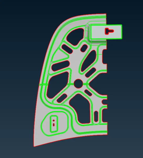
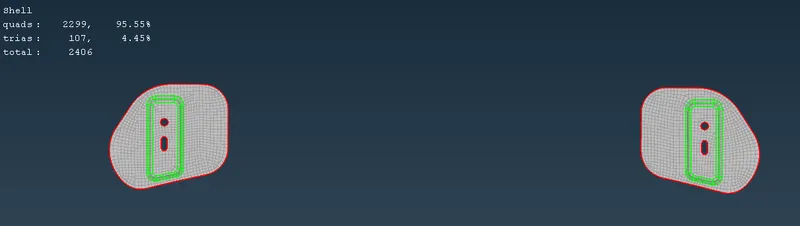
6) We then divide the components which have symmetrical shape. After this mesh have the component. For eg, the image below shows the symmetical inner_extract component.
7) For meshing we use the best mesh tool to get a good mesh of our desired parameter; Mesh> Mesh Generation> Best.
8) Before we need to set mesh parameters by going into Utilities> Mesh parameter. Also we need to create a quality criteria for the mesh which is created by Utilities> Quality criteria
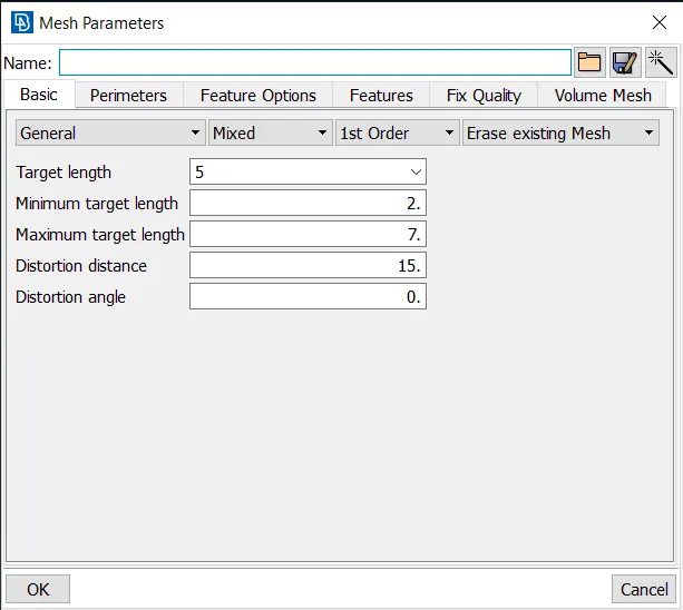
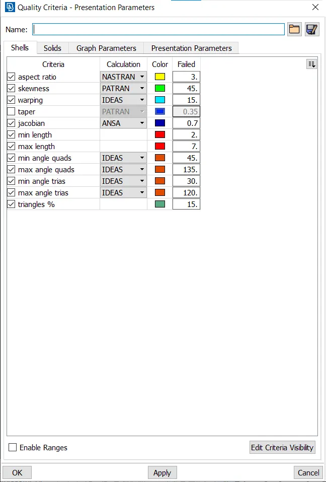
9) We now create a mesh using best too for all our components. Then we check if the elements are failing the elements are failing quality criteria by changing view to Hidden. Also if there are any opposite trias we rectify the mesh by using Paste tool or by Improve tool; Mesh>Grids>Paste and Mesh> Shell Mesh> Improve.
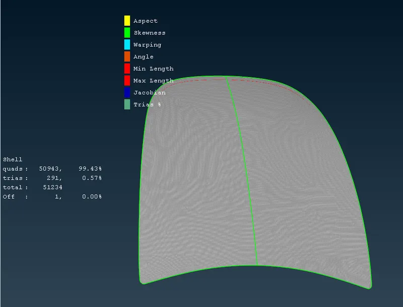
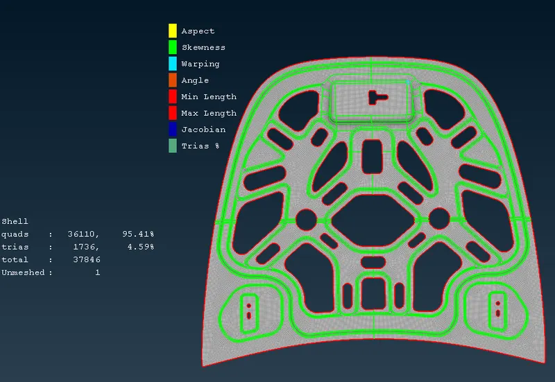
RESULTS:
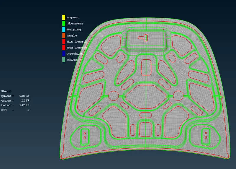
The final mesh is as shown below.
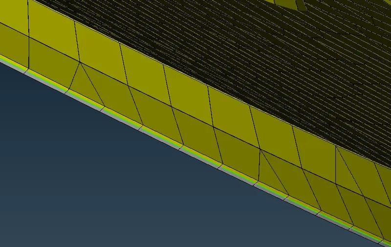
To toogle the element thickness on we check the Draw the shell as solid option in presentation parameters section in quality criteria.
The image shown below has elements with thickness enabled.
CONCLUSION AND LEARNING OUTCOME:
- In this assignment learned how to check geometry and rectify it to create a good midsurface.
- Meshing of components with best tool.
- Opposite tria reduction using paste tool and improve tool.