Week 3 - 2D meshing for sheet metal
AIM: The aim of this week challenge is to extract the mid surface of the given components and then mesh the component with given quality parameters and assign the thickness on a hood component.
PROCEDURE:
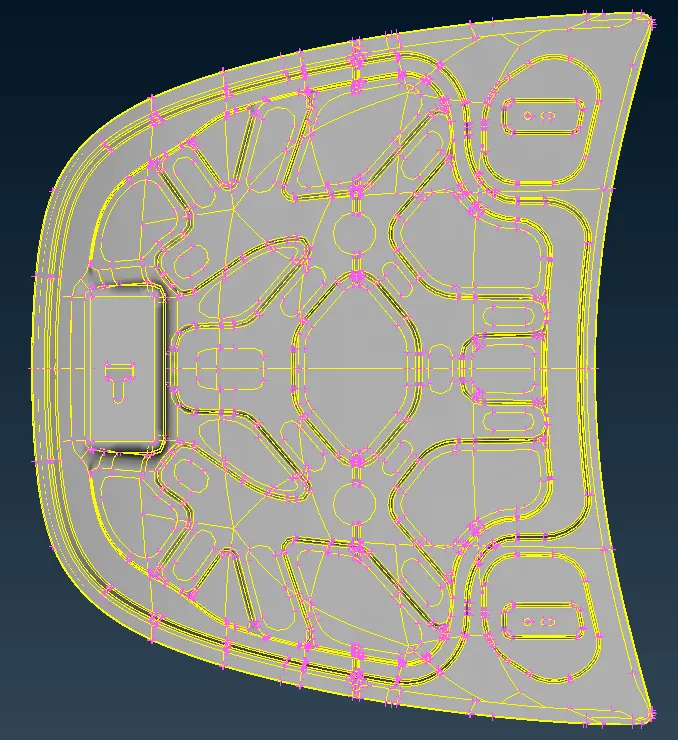
Step 1: Now open the input file in ANSA.
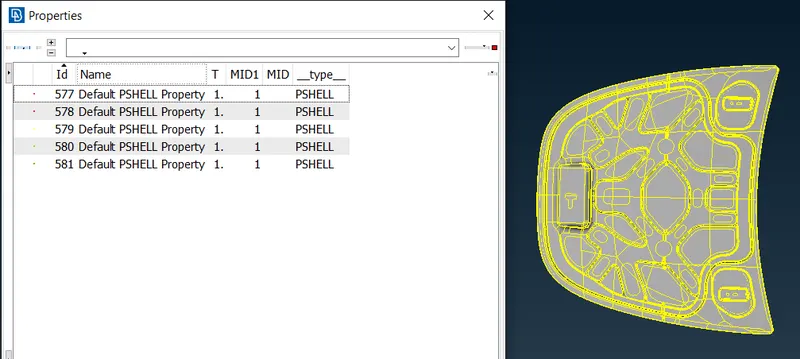
Step 2: now click the property ID card to see the components seperately.
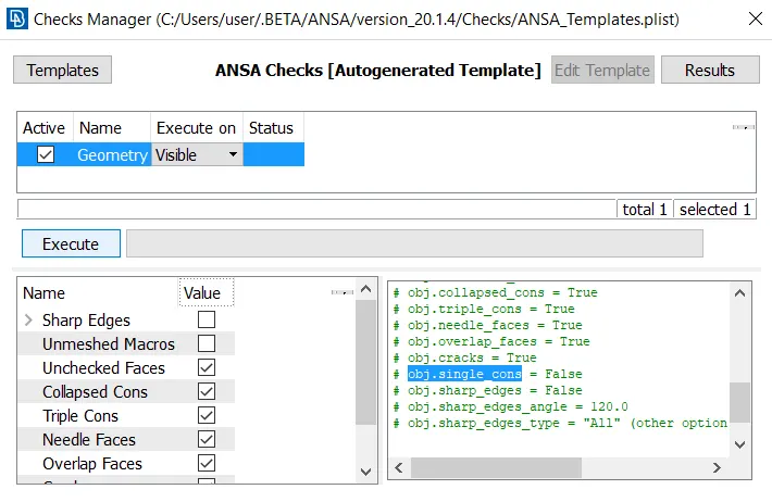
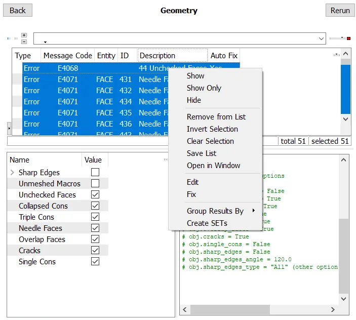
step 3: Now check the geomentry whether there is any cleanup that need to be done. The checks tool can be accessed from the upper toolbar. Checks > Geometry. With all components visible, the checks can be'executed'. The geometric discrepancies will be highlighted by the tool and they can all be selected, right clicked and fixed by clicking 'fix' as shown in the screenshot.
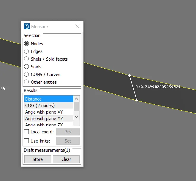
step 4: now measure the thickness of all the 4 main components and they have different thicknesses.They are as follows: Inner Panel - 0.75mm, Outer Panel - 0.75mm, Hinge Reinforcement - 1.2mm and Latch Reinforcement - 1.2mm
step 5: Now create the midsurface for all the 4 components. There are 2 ways to create the midsurface.
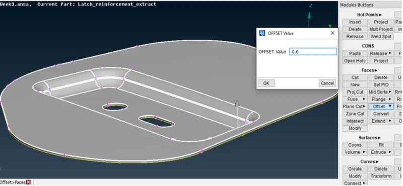
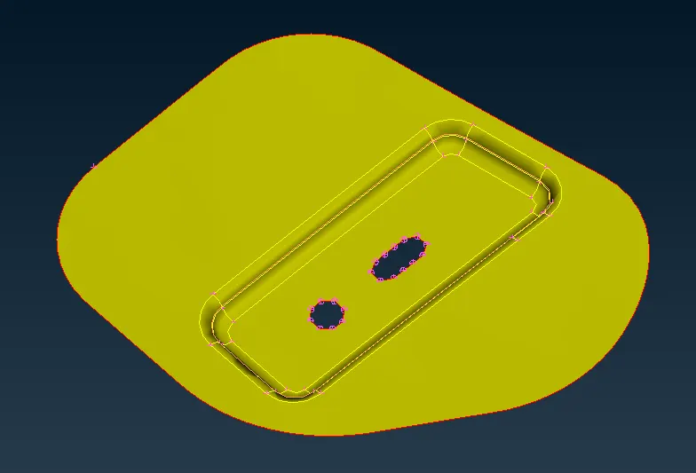
This can be done using the 'midsurface' tool in the faces menu or using the 'offset too from the Topo module. The midsurface tool would be ideal here as the components have a constant thickness. The offset tool would be more effective in cases of varying thicknesses. For practice purposes, I went with the offset tool. After selecting the offset tool, it will ask us to select the surfaces to offset. We can select the surfaces on one side of the componert. After that, we can assign the offset value (half the thickness). Do the same for the other 4 components.
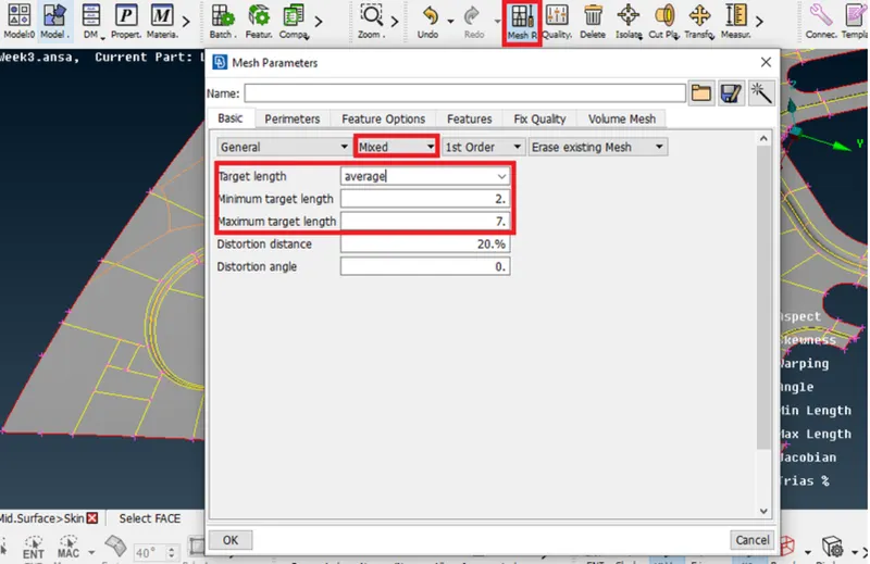
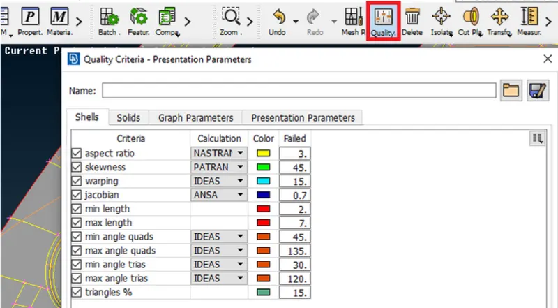
step 6: After midsurface is generated for each of the components, we can go ahead and prepare to mesh the midsurfaces. To start off, we can assign the quality parameters as per the challenge. We need to access the 'mesh parameters' and'quality criteria' options from the top toolbar. And then we can assign the values as per the table. The mesh type will be 'mixed and minimum and maximum lengths would be 2mm and 7mm respectively.
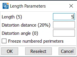
step 7:After that, we can go ahead and assign the target length. This is done by accessing the 'length' tool again from the Perimeters section under the Mesh module. We need to select the entire midsurface and assign the target length (which would be 5mm).
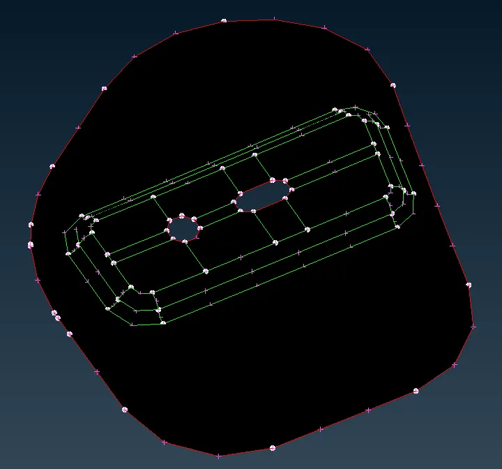
step 8: Cuts can be made using the 'Cut' tool from the Mesh module (under macros). We can go ahead and try our best to split up the surfaces to rectangular regions to ensure the least number of trias.
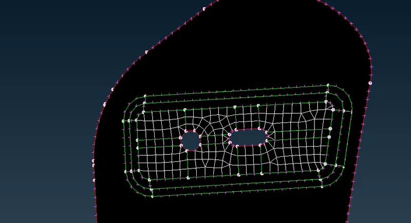
step 9: Now select the option reconstruction option under shell mesh option and remesh the elements so that the mesh can be refined more.
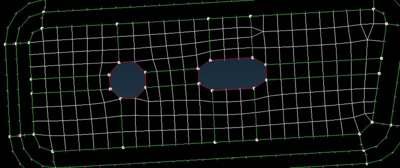
step 10: Now inorder to get a better mesh flow there are more option under the elemets tab to refine the mesh and get rid of the trias.
Now you can get rid of the opposite trias using swap option, split option under elemets tab and the paste option in grids tab.
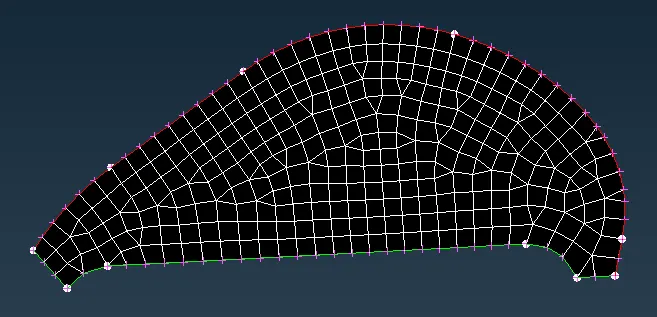
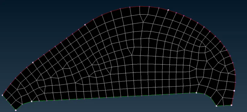
step 11:Now mesh all the four components using the above methods to get a better mesh flow and minimum trias.
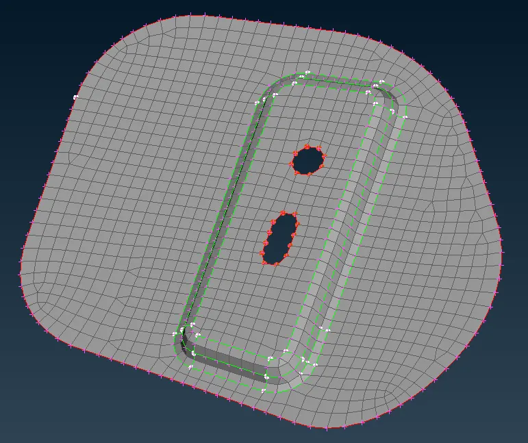
RESULT COMPONENTS:
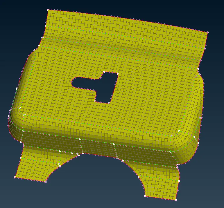
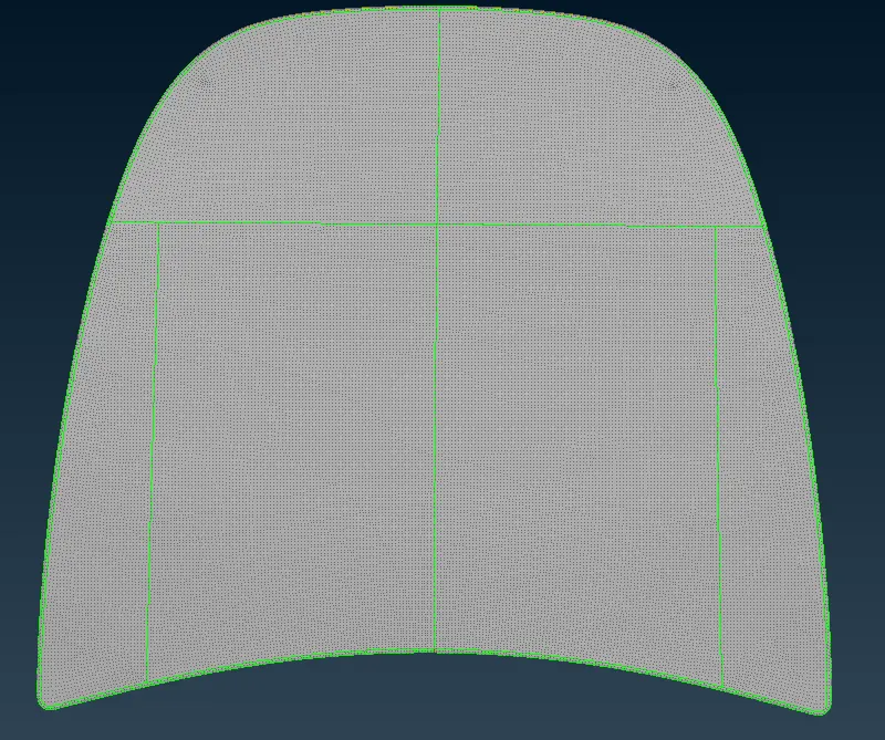
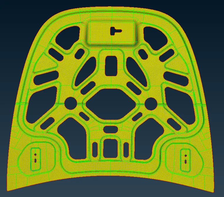
CONCLUSION:
The given hood part was meshed as per required quality criteria, after having carried out topology cleanup and generated midsurfaces for each of its components and thickness was assigned to each of them.