Week 3 - 2D meshing for sheet metal
AIM: To perform the topology clean up and extract the mid surface for all the components generate the mesh the mid surface with the given element Quality criteria for the given Hood model.
Objective: The 2D elements in the model clear the above-mentioned quality criteria and the features in the model have to be captured properly with good mesh flow.
|
S.No |
Quality Criteria |
Value |
|
1 |
Target/Average length |
5 |
|
2 |
Minimum Length |
2 |
|
3 |
Maximum Length |
7 |
|
4 |
Aspect |
3 |
|
5 |
Warpage |
15 |
|
6 |
Skewness |
45 |
|
7 |
Jacobian |
0.7 |
|
8 |
Minimum Quad Angle |
45 |
|
9 |
Maximum Quad Angle |
135 |
|
10 |
Minimum Tria Angle |
30 |
|
11 |
Maximum Tria Angle |
120 |
|
10 |
Tria Percentage |
15 |
About the component:
The component car hood is the hinged cover that rests over the engine of a front-engine vehicle. Its purpose is to provide access to the engine for repair and maintenance. A concealed latch is typically used to hold down the hood. On vehicles with an aftermarket hood and on racecars, hood pins may be used to hold down the car hood. Hoods sometimes also contain a hood scoop, wiper jets, power bulge, and hood ornament. Car hoods are typically constructed from steel and sometimes from aluminum. Aftermarket car hoods may be constructed from various other materials, including carbon fiber, fiberglass, or dry carbon. The hood design may vary from one make and model to another.
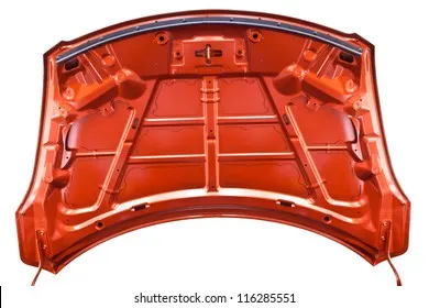
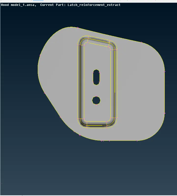
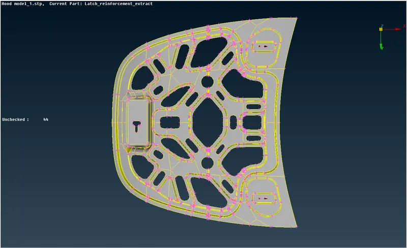
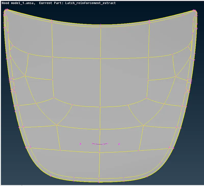
The Car hood consists of a latch, hinges, hood inside panel, and outside panel. The given car hood model is shown in the figure.
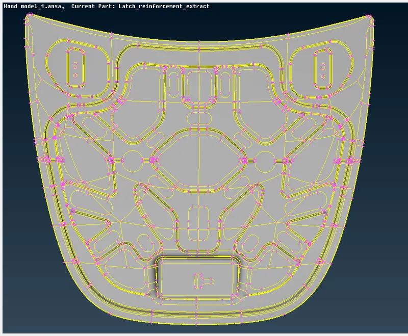
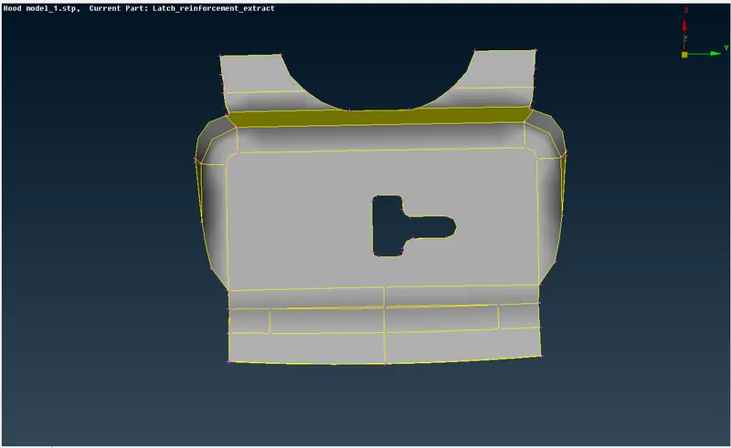
1. Latch
2. Right side hinge
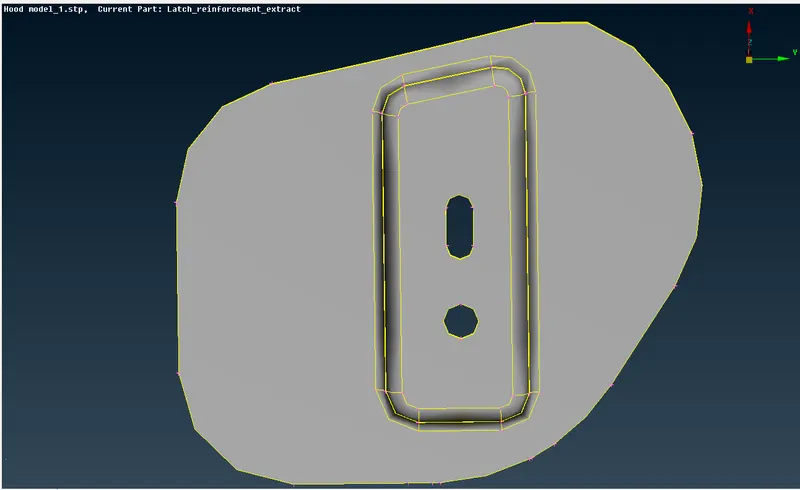
3. Left side hinge
4.Hood inside panel
5. Hood outside panel
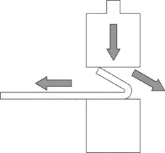
Hemming is a forming operation in which the edges of the sheet are folded or folded over another part to achieve a tight fit. Normally hemming operations are used to connect parts, to improve the appearance of a part, and to reinforce part edges. In car part production, hemming is used in assembly as a secondary operation after deep drawing, trimming, and flanging operations to join two sheet metal parts (outer and inner) together. Typical parts for this type of assembly are hoods, doors, trunk lids, and fenders.
Steps involved while meshing the component
1. 2D Geometry error check
2. Clean up Geometry
3. Topology cleanup
4. Finding thickness for the components
5. Mid surface extraction of the components
6. Assigning the values in mesh parameters and Quality criteria before meshing
7. Meshing the component according to the parameters without any errors
8. quality criteria check
9. Assigning thickness
Step 1: Import the Ansa model and 2D geometry error check.
- Import the model to the ANSA GUI window.
File > Open >Select > Import
In the properties toolbar, it will show how many components and property IDs are present in the geometry.
- The material toolbar, it will show how many material properties are available whether they are defined or not. If they are not defined, we have to switch on the mark to defined or undefined it.
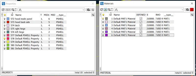
- While we importing the model, by default it is in entity mode so we have to convert it into PID mode.(Property ID)
Step 2: Geometry error checks and cleans up.
In this section, it is important to check geometry issues for the CAD models while meshing the components(Latch, Hinges, Outside and inside Panels).
Check Manager>Geometry
l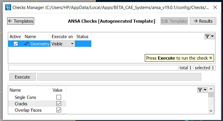
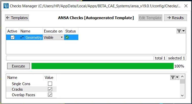
- By clicking on the execute button, it is executed for 100 percent which means there are no errors found in the components.
- If there are errors found in the component, there is an option called "Fix" by clicking on the right click on the mouse. It will auto-fix all the errors in the component.
- If there are any errors we have to clean to fix the errors automatically.
Step -3: Topology cleanup
- If there are unwanted cons on the component, it will disturb the mesh while meshing.
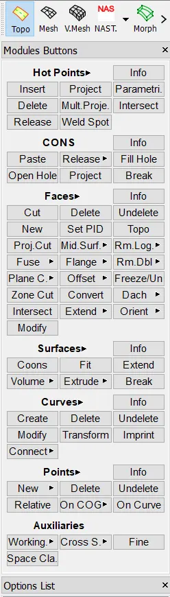
- We have to remove the unwanted cons by cut, the option in the faces module.
- Here are the modules that use in the topo mode.
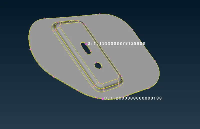
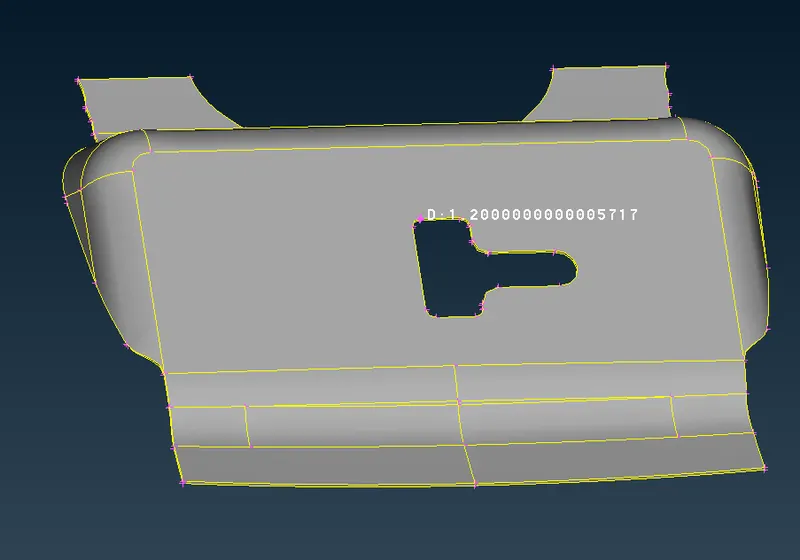
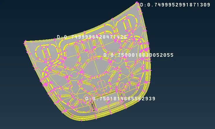
Step 4: Finding thickness for the components.
The thickness we get on checking is as follows :
- Latch =1.2 mm
- Left hinge =1.2 mm
- Right hinge =1.2 mm
- Inner extract panel =0.75 mm
- External extract panel =0.75 mm
Step 5: Midsurface extraction.
- There are two methods to extract the mid surface of the component. i.e., Manual and defeaturing.
- Here the components are extracted by the feature area command which will extract the surface of the component in one shot by assigning the offset value.
- The thickness of the latch and hinges are 0.75mm and they are offset by 1.2/2=0.6mm.
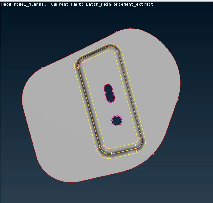
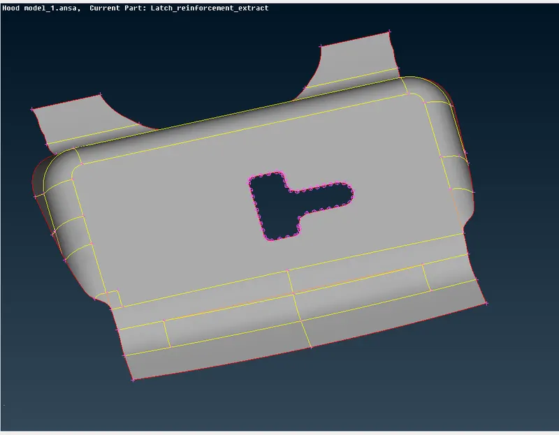
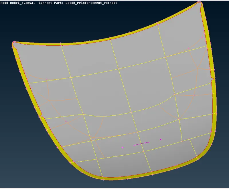
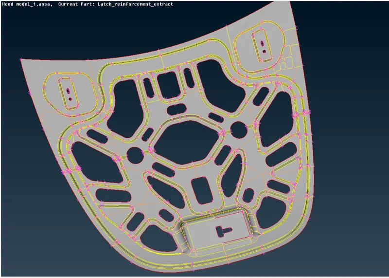
- After extracting the mid surface we have set Property Id for the mid surfaces separately.
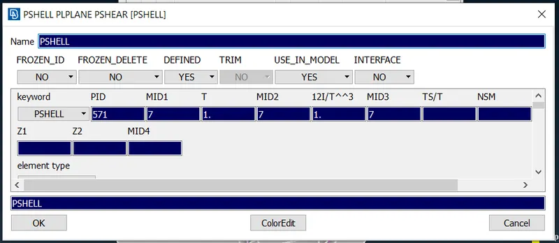
Step 6: Assigning the values in mesh parameters and Quality criteria before meshing
- Before meshing, the mesh parameters and quality criteria values have to be given.
- It will make the mesh in the correct way while meshing. The mesh parameters, where the target length should be 5mm.
- The quality criteria parameters are aspect ratio, warpage, jacobian, skewness, minimum quad angle, maximum quad angle, minimum tria angle, maximum tria angle.
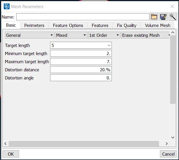
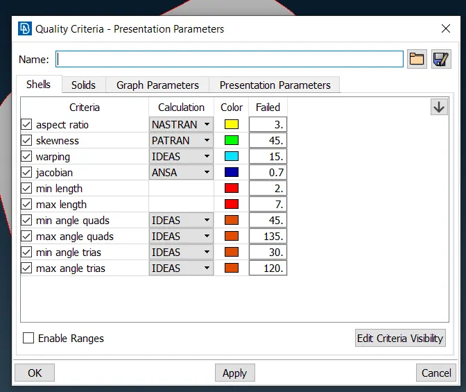
Step 7: Meshing.
- A mesh is a network that is formed of cells and points. It can have almost any shape in any size and is used to solve Partial Differential Equations. Each cell of the mesh represents an individual solution of the equation which, when combined for the whole network, results in a solution for the entire mesh.
- To create the mesh on the component, we have to switch from the topology(TOPO) module to the MESH module.
-
To apply the mesh for the component, use Best mesh for the Mesh Generation, and to remove the mesh use Erase option for the Mesh Generation.
Mesh>mesh generaton>Best
- To build the mesh quality whether is meshed already, we use Reconstruct option for better mesh in the shell mesh module.
Mesh>Shell mesh>Reconstruct
- The cut function cuts an existing macro area. It does not require the existence of Hot Points since it can directly be applied to an arbitrary position of a perimeter.
Mesh>Macros>cut
-
The split function splits quadrilateral and triangular shell elements into smaller ones. The function can be applied to individual or groups of shell elements in order to improve the mesh orientation, reduce the number of triangles, or refine locally or globally the mesh of a part.
Mesh>Elements>split
- The swap function rotates the shell edge picked by the user, inside the two shells which have that edge as common.
Mesh>Elements>Swap
- The smooth function automatically applies Smoothing attributes so as to 'relax' the mesh on already meshed Macro Areas or on FE-model shell mesh. This function may be applied to selected meshed Macro areas (Geometry) and/or FE-model shell mesh according to the chosen sub-option.
These are some of the operations while meshing.
Rules to be followed while Meshing:
- While meshing the component, the rotational patterns should be avoided in most of the rounded components.
- If unnecessary hot points are present in the component, they should be avoided.
- In the complex component, the feature area and fillet regions are to be given more attention while meshing.
- The quality criteria should show the parameters i.e., aspect ratio, warpage, jacobian, skewness, etc.
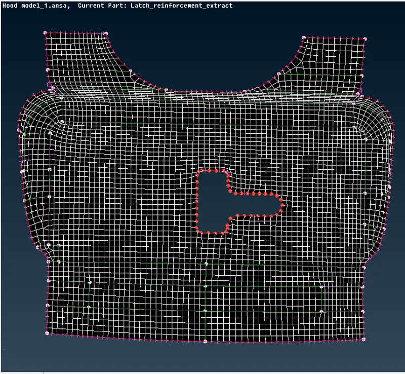
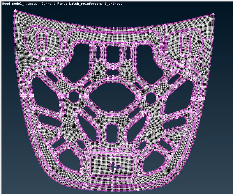
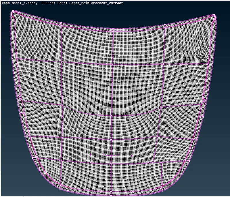
Meshed components:
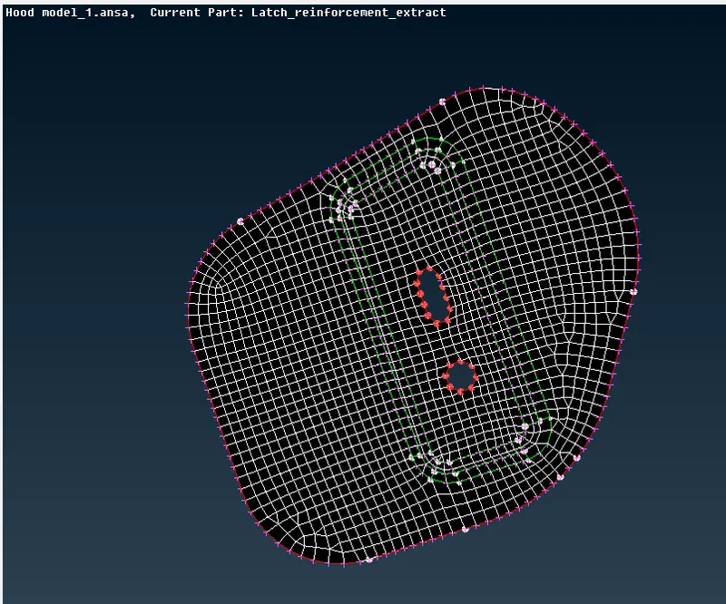
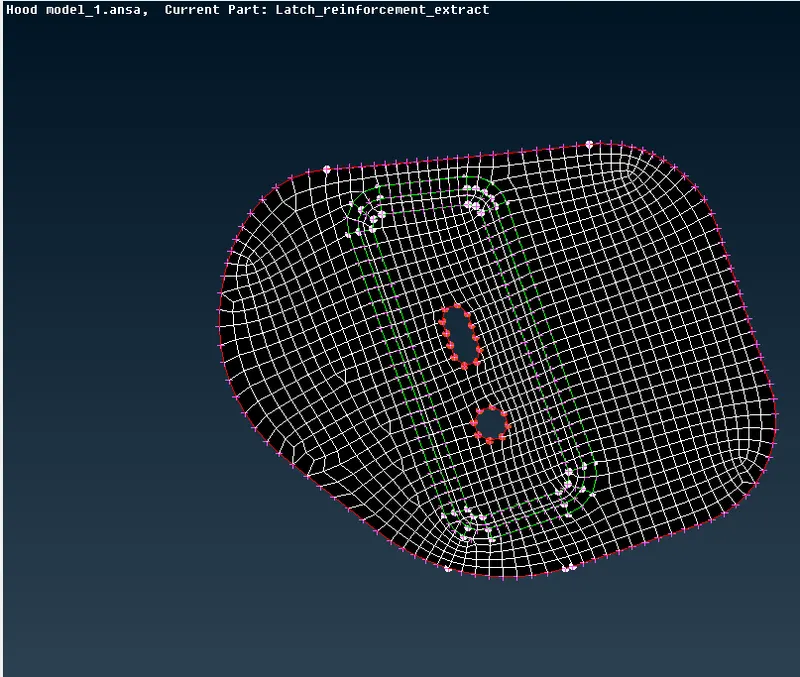
Step 8: Quality criteria check.
If there are failures in the component, we have to work on the component with minimise the failures in the components.
Step 9: Assigning thickness
In the property manager, by assigning the thickness value in the T option. This gives the earlier results for the respected property IDs.
Learning outcomes :
- Performing geometry clean up for the complex sheet metal components
- Extracting the mid surface for the complex components.
- Assigning property IDs for the newly created mid-surface extracts.
- Assigning Mesh parameters and quality criteria parameters.
- Generation of the mesh by meeting the good quality parameters.
- Identification of the quality criteria failures and resolve the issue and improve the quality of the component.
- Assigning thickness for the newly created mid surface after meshing.
GOOGLE DRIVE LINK: