Week 2 Railwheel and Track
AIM :-
Perform a static structural analysis on the Railwheel and Track setup and
Case 1: Multiply the bearing load by 5 times and compare the results with the load of 100000 N . Compare the Total Deformation, Equivalent stress and the life under both the loads
Case 2: Implement a User defined result and calculate the Total Deformation from this result and check if it is the same as that obtained by the inbuilt result by ANSYS for a load of 100000 N.
CASE SETUP :-
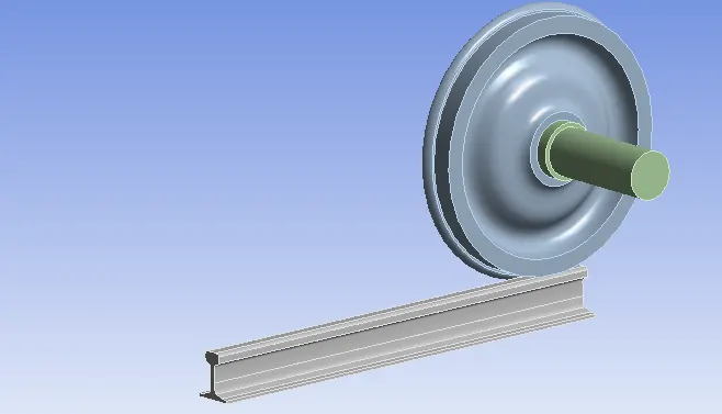
- import the given cad model into ansys workbench
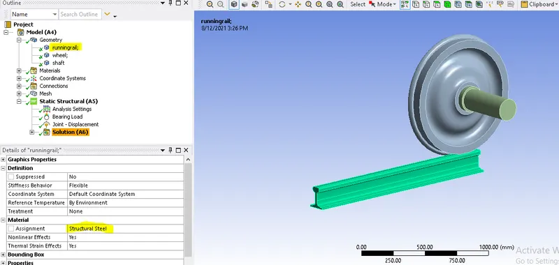
- Rename the components as Running_rail , wheel & Shaft assign structural steel as material.
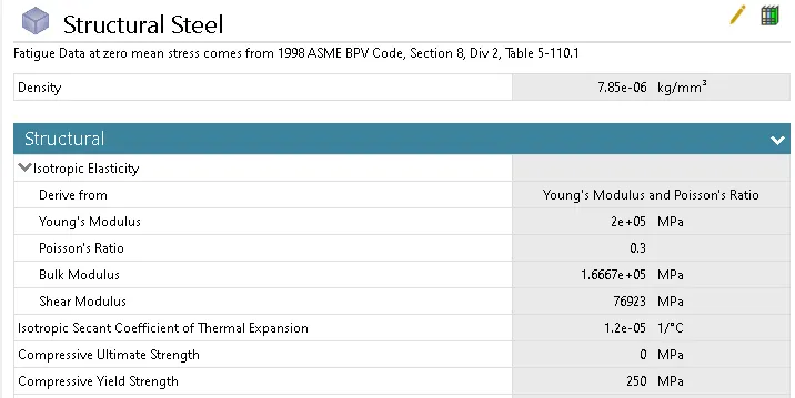
- properties of material

- Contacts - 1.Frictional contacts were setup between Runnng_rail & Wheel with a friction coefficient of 0.3. To avoid unnecessary complexity select necessary faces that comes into contact during simulation.
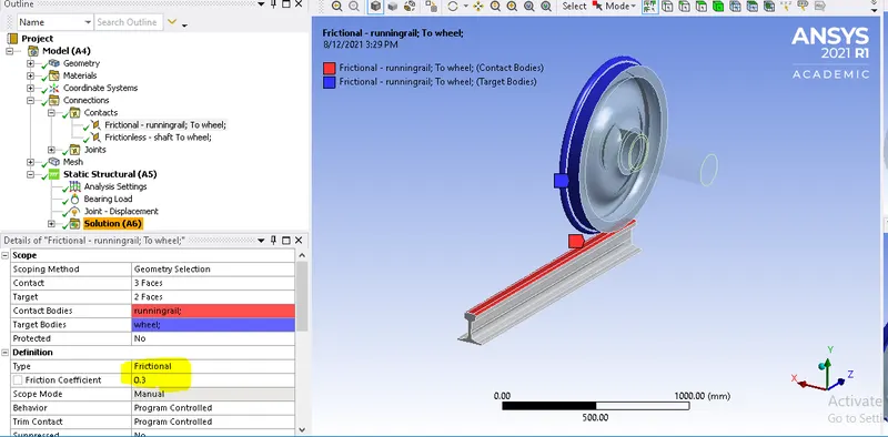
2. Friction less contacts were setup between Shaft and Wheel.
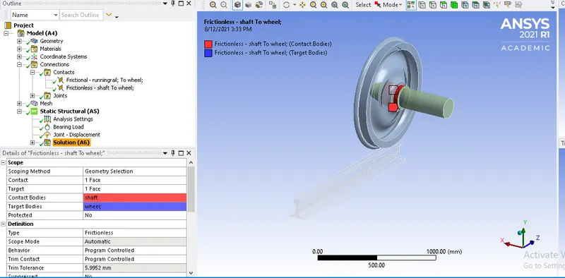
- Joints - Total 3 joints are setup between Running_rail , wheel & Shaft w.r.t. ground.
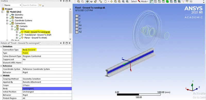
Fixed Joint
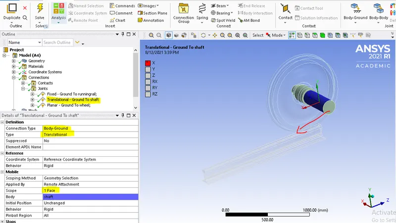
Translational Joint
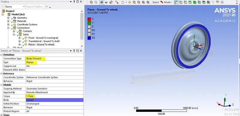
Planarl Joint
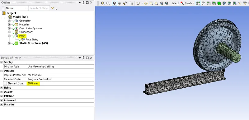
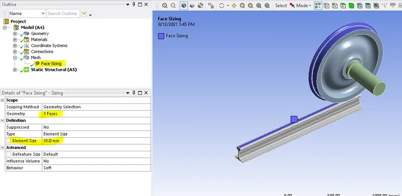
- Mesh - generated mesh for total body of components with an element size of 50mm ,to get better results refine contact surfaces of Rail & wheel with an element size of 35mm using Face sizing option
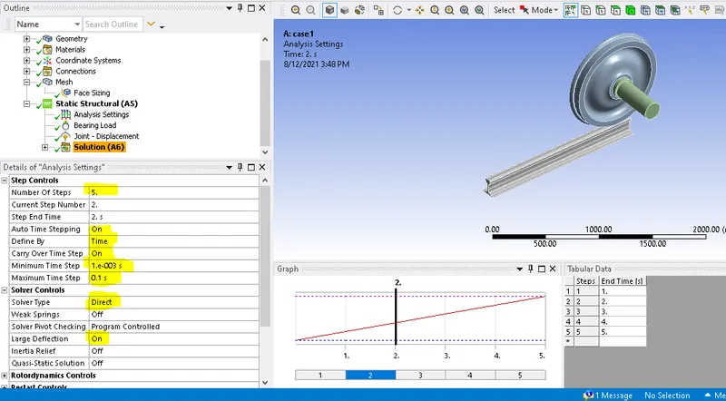
Analytical settings - this analysis setup for 5 steps, this doesn't control time step, but it is only indication of points where boundary conditions change. the time step is auto controlled by minimum ,initial maximum and time steps
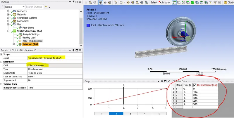
- Boundary conditions
Joint displacement
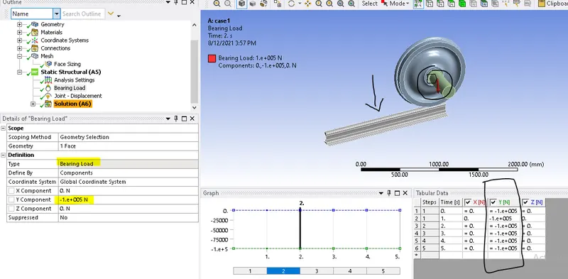
Bearing load with a value of 1e5n
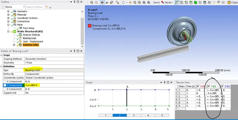
Bearing load with a value of 5e5n
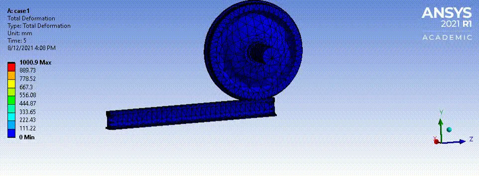
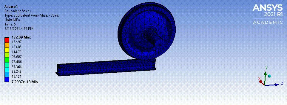
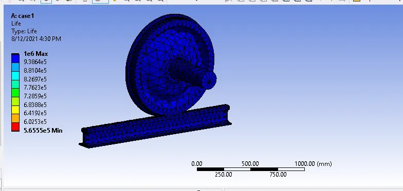
RESULTS FOR LOAD OF 1e5
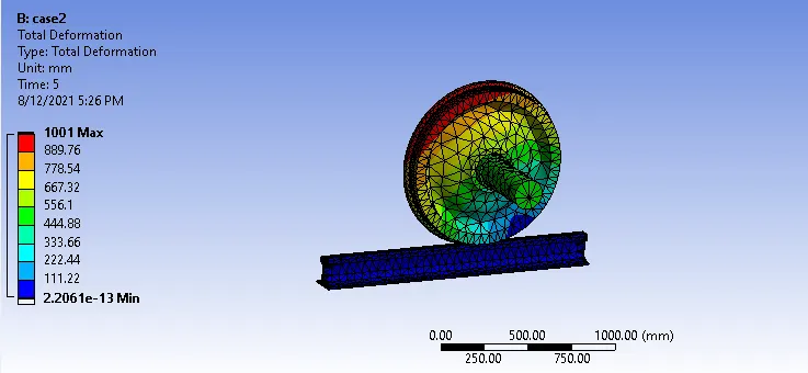
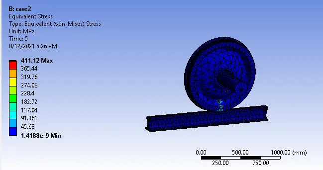
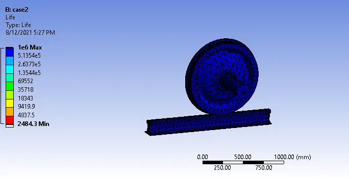
RESULTS FOR LOAD OF 5e5
CASE -1 comparision of results with load of 1e5 and 5e5
| Total deformation (mm) | Equivalent stress (mpa) | Life (min no.of. cycles) | |
| Load - 1e5 | 1000.9 | 95.169 | 5.6555e5 |
| Load - 5e5 | 1001 | 411.12 | 24834.3 |
- 1. comparing the results for both cases, we can observe that there is no change in total deformation
- 2. Equivalent stress increased with increase in load, so it is obvious that stress in case 2 is higher.
- 3. The max equivaent stress occures at the rail and wheel contact point.
- 4. max. Fatigue life is same for both cases but there is a drastic change in min Fatigue life.
- 5.min. fatigue life is more for case 1.
CASE -2 comparision of user defined total deformation result with deformation of 1e5 Load.
- when an analysis performed displacement occures in 3 directions, X Y and Z
- Total deformation is the overall deformation of the system and it is the sq.root of the summation of the square of X - direction , Y - direction, Z- direction.
expression for total deformation
Total deformation = SQRT (X^2+Y^2+Z^2)
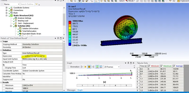
- The obtained user defined deformation result (1000.9) is same as the ansys inbuilt result (1000.9).
Google drive link
https://drive.google.com/file/d/1W0nwHrtMfGgoqhsMFg6vv2KIPoW1Ahuh/view?usp=sharing