Week 2 Railwheel and Track
STATIC STRUCTURAL ANALYSIS ON THE RAILWHEEL AND TRACK USING ANSYS
OBJECTIVE
To perform a static structural analysis on the Railwheel and Track setup for the following case study,
Case 1: To multiply the bearing load by 5 times and compare the results with the load of 100000 N. Compare the Total Deformation, Equivalent stress and the life under both the loads
Case 2: To implement a user defined result and calculate the Total Deformation from this result and check if it is the same as that obtained by the inbuilt result by ANSYS for a load of 100000 N.
1. THEORY

Fig. 1 Railwheel Track assembly.
A train wheel or rail wheel is a type of wheel specially designed for use on railway tracks. The wheel acts as a rolling component, typically pushed onto an axle and mounted directly on a railway carriage or locomotive. The powered wheels under the locomotive are called Driving Wheels. Wheels are initially cast or forged and then heat-treated to have a specific hardness. New wheels are machined using a lathe to a standardized shape, called a profile, before being installed onto an axle. All wheel profiles are regularly checked to ensure proper interaction between the wheel and the rail. Incorrectly profiled wheels and worn wheels can increase rolling resistance, reduce energy efficiency and may even cause a derailment.
Rail generally suffers from very high stresses and has complicated stress zone with bending stresses, contact stresses and thermal stresses acting at a time. Continuous interaction of rail wheel interface results in high frictional stress, contact pressure and ultimately wear. Wear modifies wheel and rail profile, which as a matter of fact changes the nature of contact between rail and wheel and consequently may increase the Rolling Contact Fatigue rate, and results in shallow crack propagation in rails. Rolling Contact Fatigue can trigger damage and can lead to surface crack by the action of wear on the rail or by plastic deformation of the material.
Area prone to wear is manifested by loss in material or plastic flow of metal. Thus, the profile of rail gradually changes because of high train traffic, enormous contact stresses, environmental conditions, etc. leading to failure.
2. ANALYSIS SETUP
2.1 Geometry:
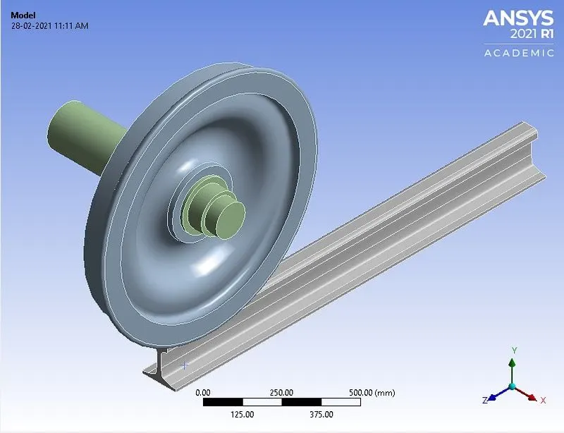
Fig.2.1 3D model of Railwheel track assembly.
The given 3D model of Railwheel track assembly is imported into ANSYS Workbench for static structural analysis.
2.2 Material Properties:
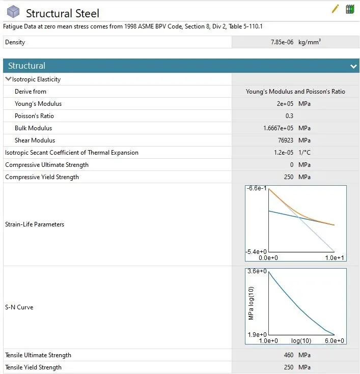
Fig.2.2 Material property details.
The material considered for analysis of Railwheel track assembly is structural steel.
2.3 Contact Details:
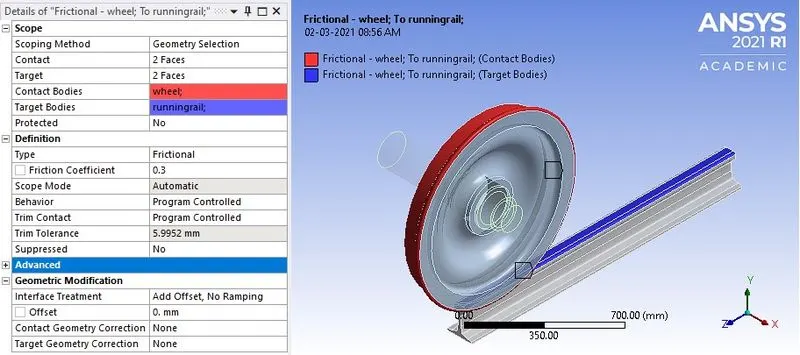
a. Contact between Wheel and Track
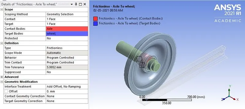
b. Contact between Wheel and Axle
Fig.2.3 Contact details of Railwheel Track assembly.
Contact was assigned at two locations i.e. in between (a) wheel and track; (b) wheel and the axle. The contact between the Wheel and Running Rail is assigned as frictional contact with coefficient of friction μ = 0.3. As the shape of wheel at the contact is in convex form, hence it is selected as Contact Body and rail is relatively flat therefore it is selected as Target body.
Contact between wheel and the axle is initialized as frictionless contact that means sliding is possible without loss in energy. Here the periphery of the wheel is made target whereas, the outer surface of the axle is made contact. Therefore, larger surface is target body and smaller surface is contact body.
2.4 Joint details:
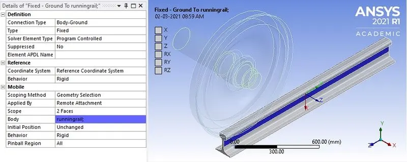
a. Fixed Support.
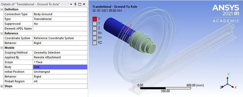
b. Translational Joint
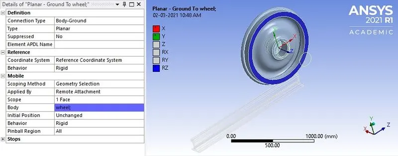
c. Planar Joint
Fig.2.4 Joint details.
All the joint connection type is set to body to ground. The running rail is fixed by constraining all degrees of freedom. The motion of the axle has to translate the wheel along the track. Hence, the type of joint assigned to axle is translational along x-axis. The wheel has to be in a particular plane while in motion to ensure stability. Hence, planar joint is applied to flat surface on the wheel. This boundary condition allows the motion of wheel in x and y coordinates and rotation about z-axis.
2.5 Meshing:
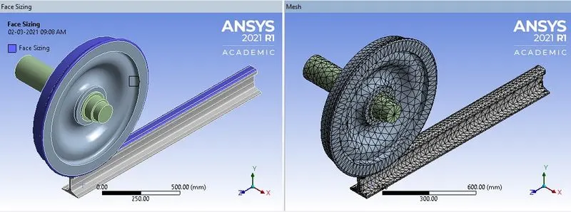
Fig.2.4 Meshing details of Railwheel Track assembly.
The Railwheel Track assembly is meshed with element size of 35 mm. The element size on the regions of contact between wheel and track is also set as 35 mm using face sizing option to better capture structural behavior at the contact region while reducing solve time. The total number of nodes and elements generated are 18070 and 9171 respectively.
Note:
The academic version of software has the problem size limit of 128k nodes or elements.
2.5 Boundary Conditions:
2.5.1 Analysis settings:
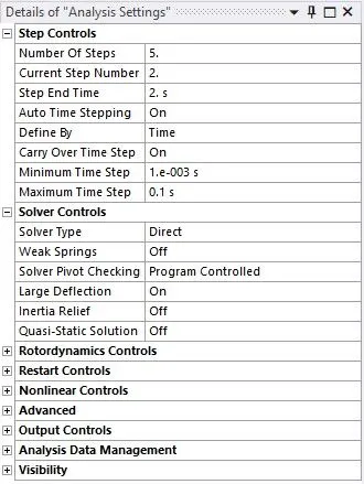
Fig.2.5.1 Analysis settings.
The total number of steps for analysis is specified as 5. For step 1, auto time stepping is program controlled. For step 2 to 5 auto time stepping is set to ‘On’ with the minimum and maximum time step being specified as 1e-3 s and 0.1 s respectively. For all the steps, under solver control, the large deflection is set to ‘On’ and solver type is selected as ‘Direct’. Under non-linear control, force convergence is set to ‘On’ and the all the output controls are set to ‘Yes’.
2.5.2 Joint load details:
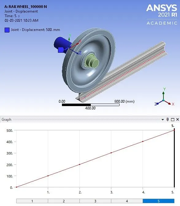
a. Translational load.
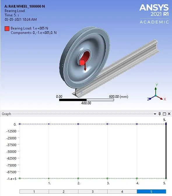
b. Bearing Load.
Fig.2.5.2 Joint load details.
The wheel has to translate along the running rail, hence for analysis purpose a translational joint load in the form of displacement of 500 mm with increment of 100 mm in each step is applied with varying linearly with time.
Since, the load of the carriage or bogie is transferred to wheel, a bearing load of 100000 N is applied in negative y direction to each wheel for the first iteration and for second iteration the load is increased to 500000 N. The simulation is carried out for these bearing load separately and the results are compared.
3. RESULTS AND DISCUSSIONS
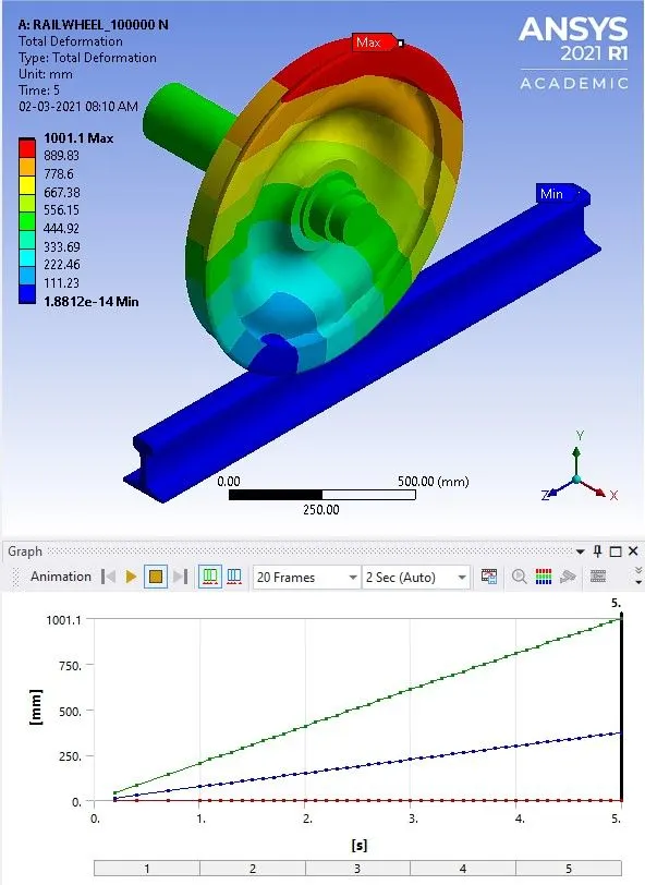
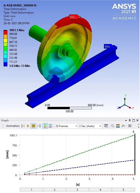
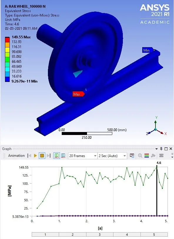
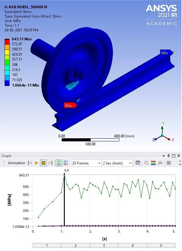
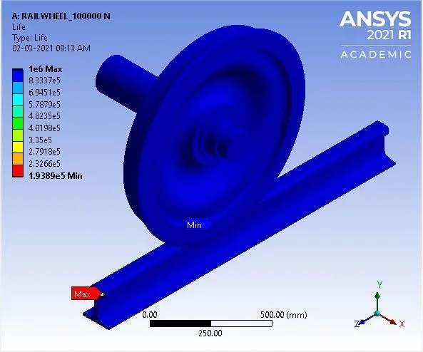
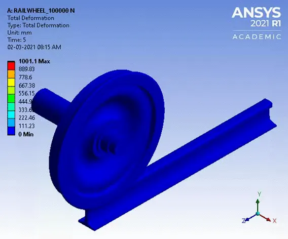
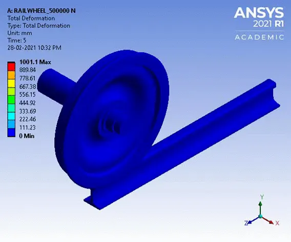
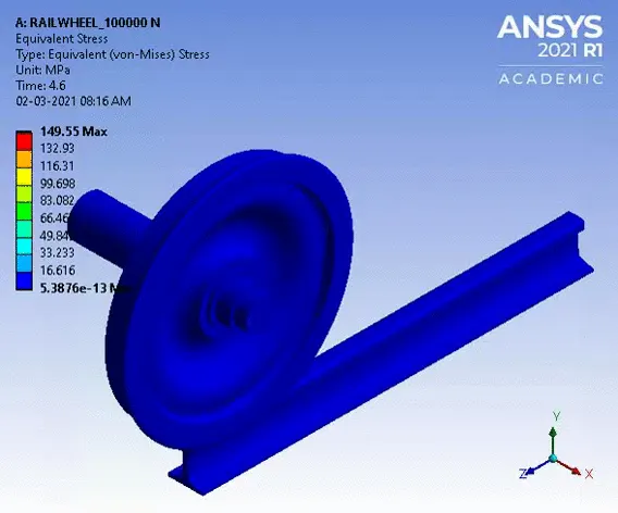
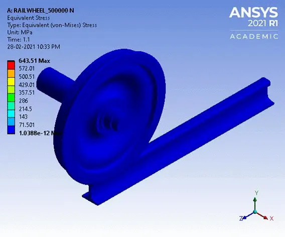
Case-1: Comparison of results such as the Total Deformation, Equivalent stress and the life under the bearing loads of 100000 N and 500000 N.
3.1 Total Deformation:
a. Bearing load 100000 N b. Bearing load 500000 N
Fig.3.1 Total Deformation
3.2 Equivalent (v-m) stress distribution:
a. Bearing load 100000 N b. Bearing load 500000 N
Fig.3.2 Von-Mises stress distribution.
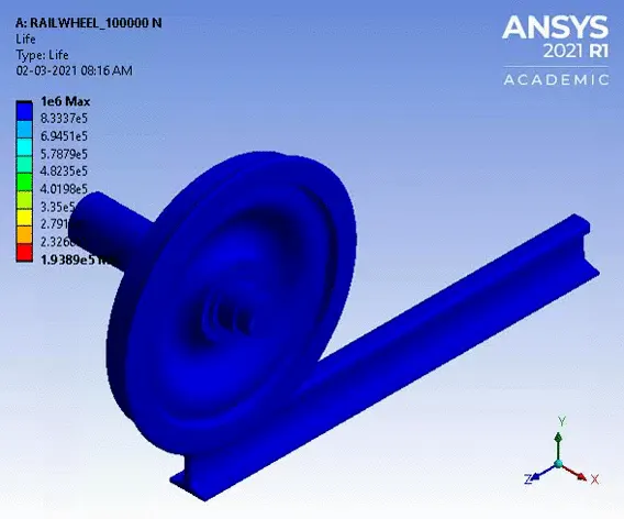
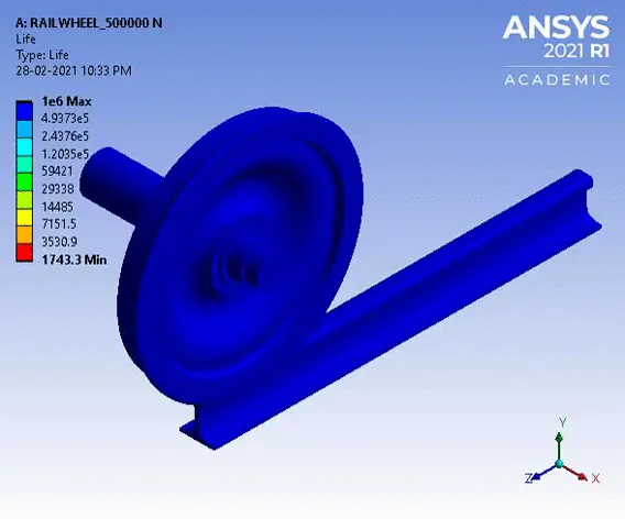
3.3: Fatigue Life:
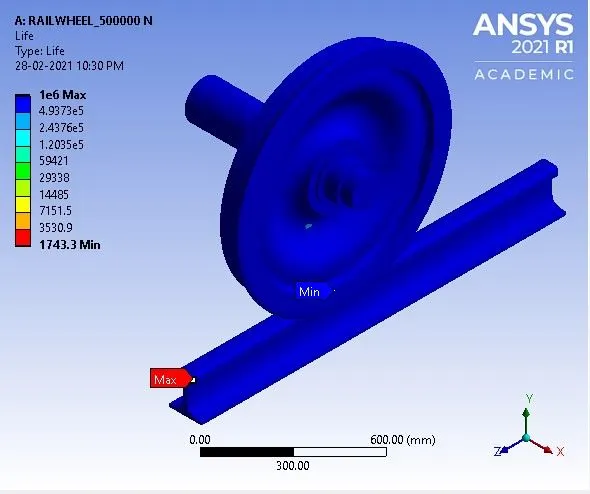
a. Bearing load 100000 N b. Bearing load 500000 N
Fig.3.3. Fatigue Life
Case-2: User defined results of displacement.
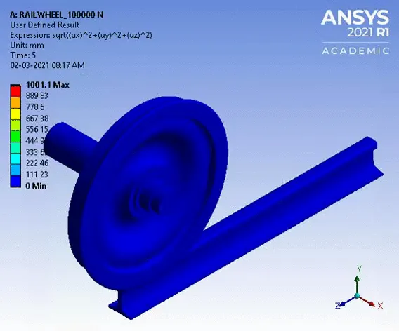
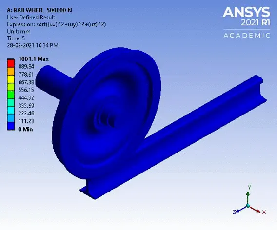
3.4. User Defined Result-Displacement:
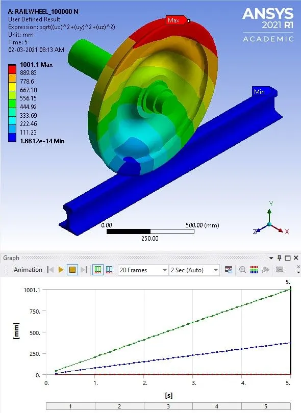
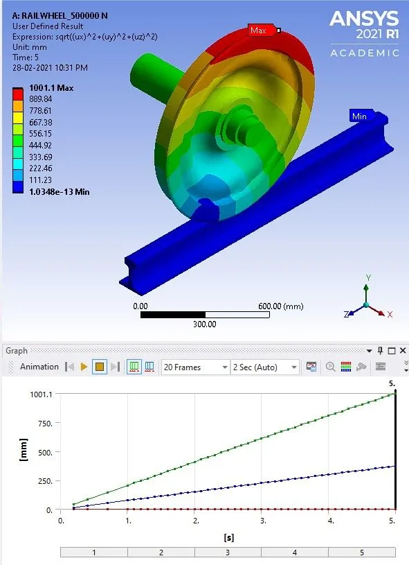
a. Bearing load 100000 N b. Bearing load 500000 N
Fig.3.4. User defined result (displacement).
Deformation results generally obtained in ANSYS WorkBench as total deformation or directional deformation. Both of them are used to obtain displacements from stresses. The main difference is the directional deformation calculates for the deformations in X, Y, and Z planes for a given system. In total deformation, it gives a square root of the summation of the square of x-direction, y-direction and z-direction. The expression used for obtaining user defined result for displacement is,
`"Total deformation"=sqrt((ux)^2+(uy)^2+(uz)^2)`
3.5. Comparison of Results:
The maximum and minimum values of Total Deformation, Equivalent (v-m) Stress, Fatigue life and user defined displacement result is tabulated as shown below.
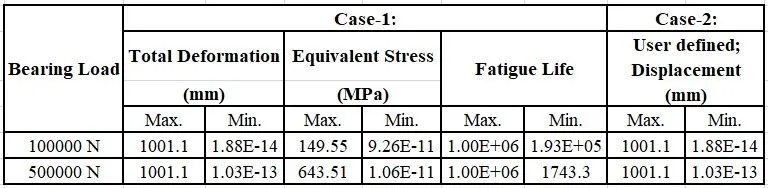
From the table, it is observed that the increasing the magnitude of bearing load does not influence the value of total deformation. The value of user defined result obtained for displacement is same as that of the total deformation, hence the expression used validates the output result.
The maximum value of v-m stress for a bearing load of 100000 N is 149.55 MPa which is below the yield stress value of the material i.e., 250 MPa. Hence the rail and wheel can sustain the load.
The maximum value of v-m stress for a bearing load of 500000 N is 643.51 MPa which is above the ultimate stress value of the material i.e., 460 MPa. Hence the rail and wheel cannot sustain the load and eventually leads to failure.
The minimum fatigue life of rail and wheel is 1.93e5 cycles for a bearing load of 100000 N. Hence, rail and wheel are having almost infinite life.
The minimum fatigue life of rail and wheel is only 1743.3 cycles for a bearing load of 500000 N. Hence, the life of the rail and wheel is drastically reduced as the bearing load is increased which leads to failure of the components within a short span of service condition.
3.6. Animation of Results:
Case-1:
Total Deformation:
a. Bearing load 100000 N b. Bearing load 500000 N
Equivalent stress distribution:
a. Bearing load 100000 N b. Bearing load 500000 N
Fatigue life:
a. Bearing load 100000 N b. Bearing load 500000 N
Case-2:
User Defined Result-Displacement:
a. Bearing load 100000 N b. Bearing load 500000 N
CONCLUSION
- Static structural analysis on the Railwheel and Track setup were performed for both loading conditions i.e., i) bearing load is 100000 N, ii) bearing load is 500000 N.
- The results of Total Deformation, Equivalent stress and the life under both the loads were compared and found that Railwheel and track assembly can withstand the bearing load of 100000 N but increasing the bearing load to 500000 N leads to failure of the components.
- User defined result obtained for the expression of displacement is same as that obtained by the inbuilt result by ANSYS for both the loading conditions.