Week 2 Railwheel and Track
OBJECTIVE:
Perform a static structural analysis on the Railwheel and Track setup and compare results from both the cases.
Case 1: Compare the results with the bearing load of 100000 N Vs 500000. Total Deformation, Equivalent stress and the fatigue life under both the loads
Case 2: Implement a User-defined result and calculate the Total Deformation from this result and check if it is the same as that obtained by the inbuilt result by ANSYS for a load of 100000 N.
Setup:
Mesh Settings:
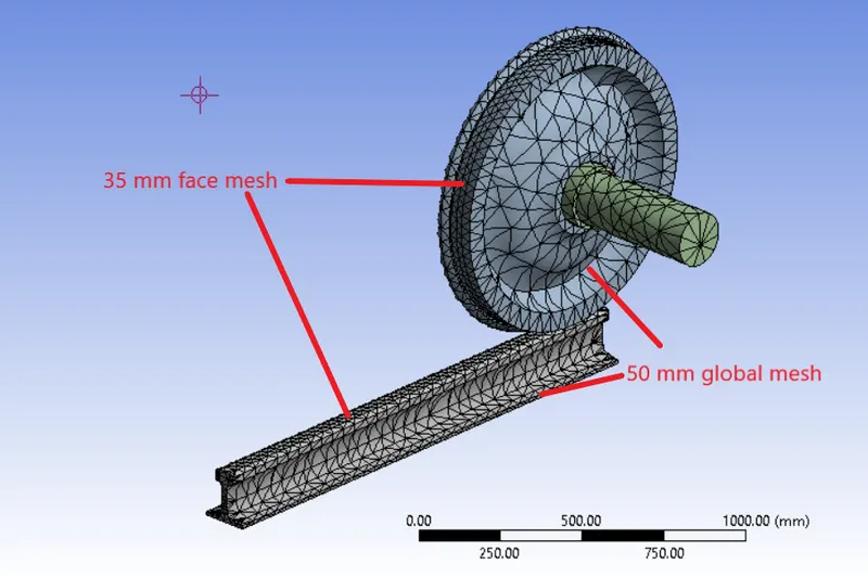
Element type: Tetrahedral
Global element size = 50mm
Face sizing element size = 35mm
Face sizing is applied to the contact regions in the model i.e. the wheel and track surfaces in contact and the wheel hub inner surface and the axle surface in contact.
Contact settings:
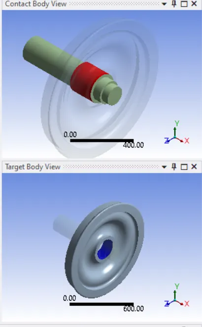
Contact between wheel and axle: Frictionless Contact
Here, the frictionless contact is provided between the axle and the wheel in order to mirror a bearing which facilitates the rotational movement of the wheel and the non-rotation of the axle. Here, the axle
transfers all the loads into the wheel and that is why the wheel is kept as the target body and the axle is kept as the contact body.
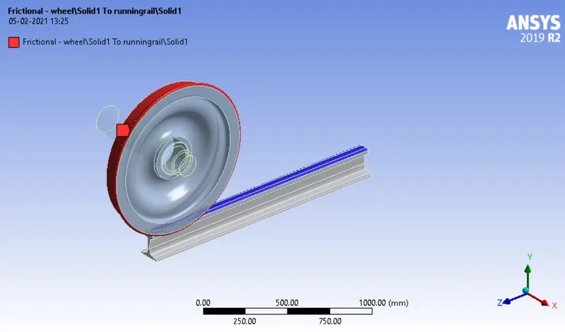
Contact between wheel and track: Frictional contact (coefficient of friction = 0.3). Here, the load from the wheel is transferred into the tracks through their frictional contact and thus, the track is the target
body and the wheel is the contact body.
Joints:
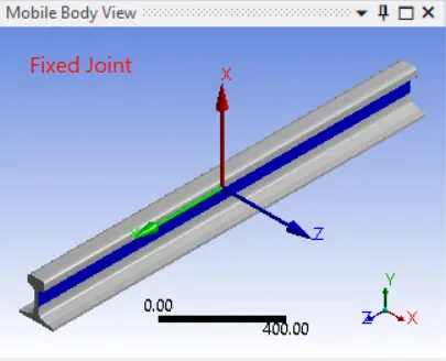
Since the track is supposed to be fixed to the earth, a fixed joint is applied to the track with the ground body as the reference.
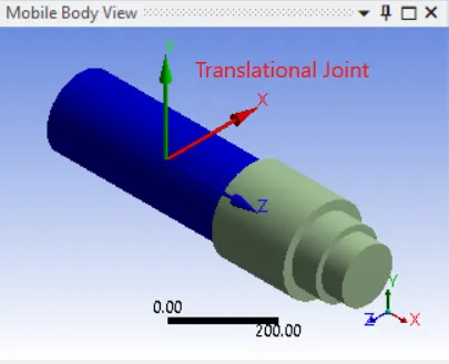
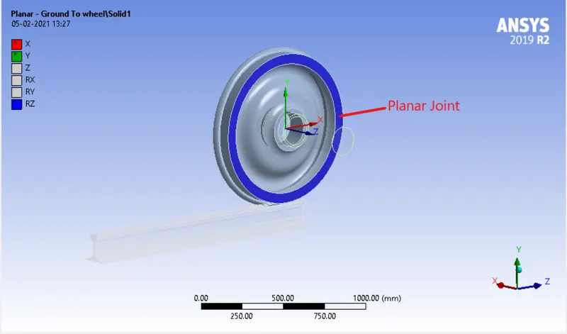
The axle is assumed to be a translational joint between the axle and the ground is defined. Since the axle doesn’t rotate and the wheel has to rotate, a frictionless contact is used between the two to felicitate the sliding of the rotating wheel over the axle body. Since the wheel has to rotate and translate simultaneously, a planar joint is defined between the wheel and the ground allowing translation in the X and Y-axis of the joint coordinate system and rotation about the Z-axis of the joint coordinate system.
Joint Loads:
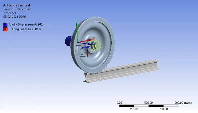
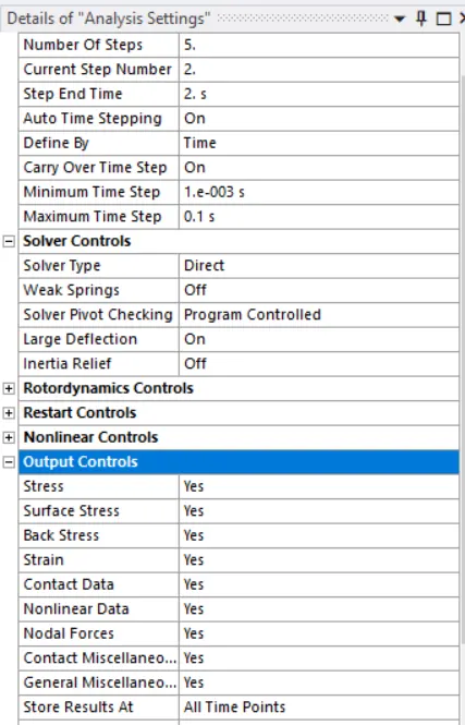
A translational motion is introduced in a gradual manner to the translational joint of the axle by introducing it in 5 load steps and the total distance to be covered by the motion is 500 mm (100 mm in each load step). Basically, due to the contact between the axle and the wheel, the translational motion is transferred to the wheel and since its DOF is restricted to the X-Y plane defined by the planar joint, it starts rotating
and translating forward over the track by the virtue of its frictional contact with the track.
Bearing Loads:
The axle is responsible for transferring loads to the wheel. The loads transferred to the wheel may include the weight of the axle, the weight of the carriage above the wheelset and other loads. To provide a general representation of these loads, a vertical bearing load is introduced which acts on the inner contact surface of the wheel and has a magnitude of 100 kN.
Analysis Settings:
Results:
Equivalent Stress (Von-Mises):
100 kN 500 kN
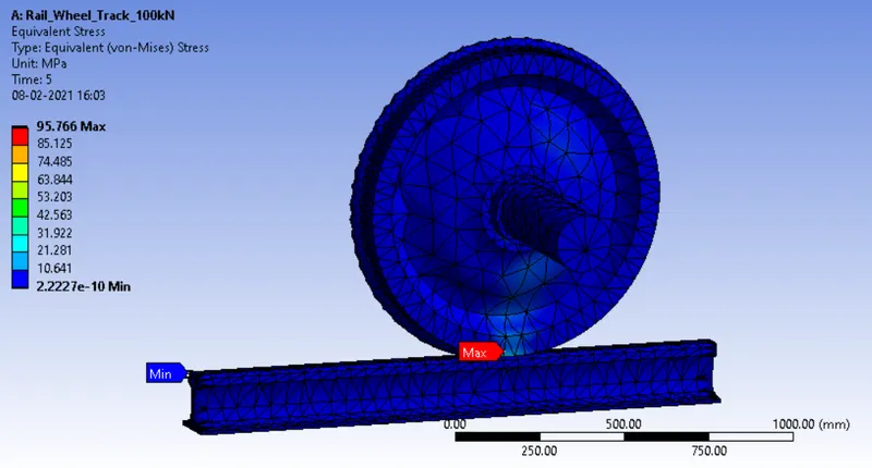
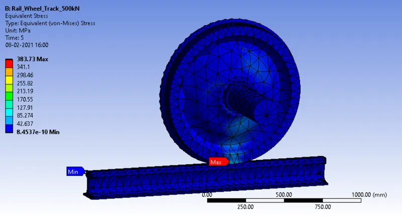
Equivalent Strain (Von-Mises):
100 kN 500 kN
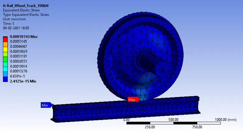
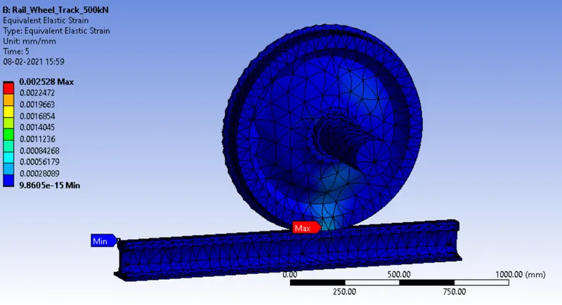
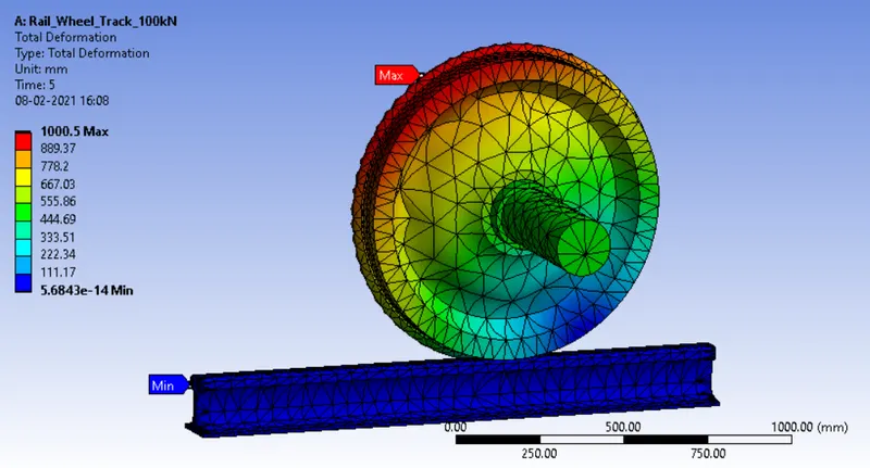
Total Deformation:
100 kN 500 kN

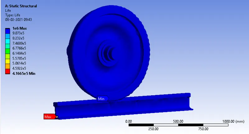
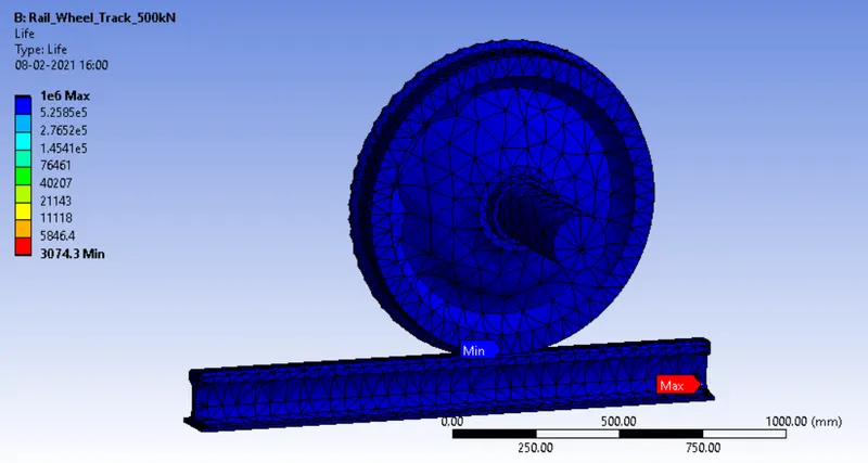
Fatigue Life:
100 kN 500 kN
Google Drive Link:
https://drive.google.com/file/d/1Qu6WPOIKBb1uXrfTDEPYPcwUz1vJC2HY/view?usp=sharing