Week 2 Railwheel and Track
RAILWAY TRACK WHEEL CHALLANGE
Modelling: Model provied for this challange is Parasolid file(.x_t).
Parametters:
1.contacts:
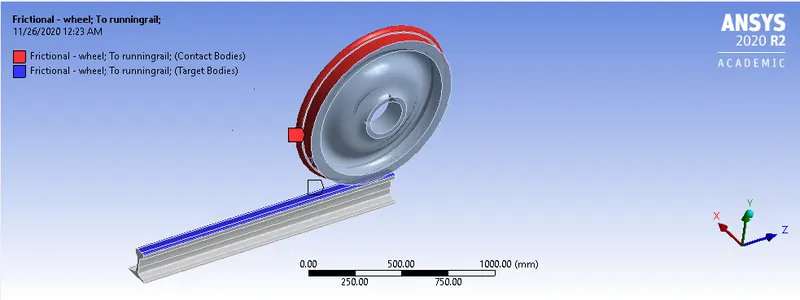
- Frictional contact between wheel and rail:
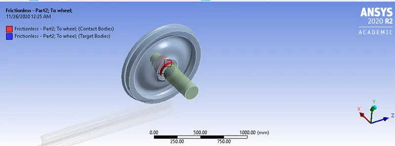
Frictionless contact between wheel and shaft:
2.Joints:
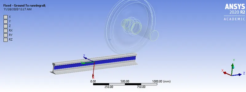
- Fixed joint for rail:
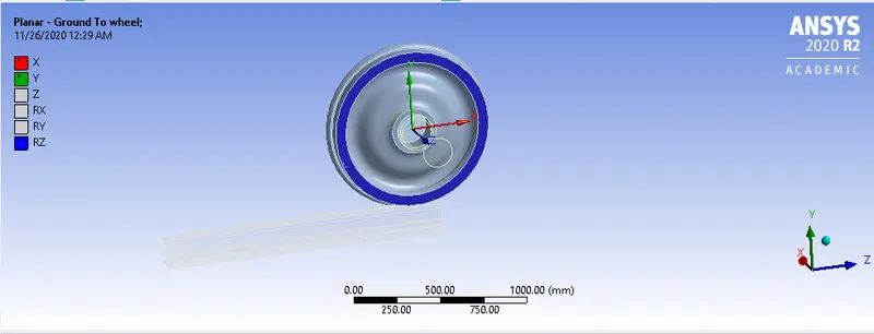
- Planar Joint:
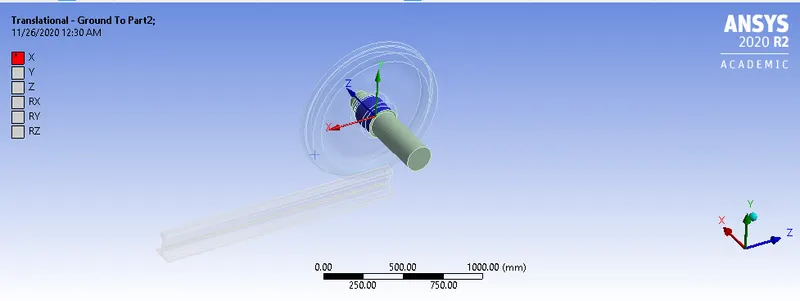
- Translational Joint for shaft:
3.Analysis Settings:
All parameters in analysis setting are taken as per video.
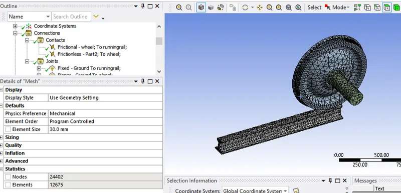
4.Meshing:
Global mesh size=30mm
Sizing 2 faces with mesh element size=25 mm
Case 1:
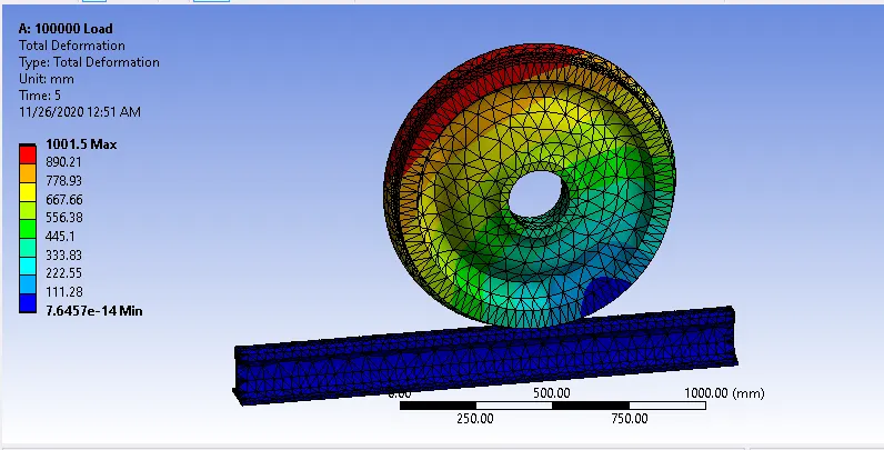
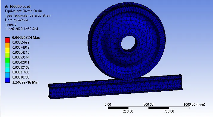
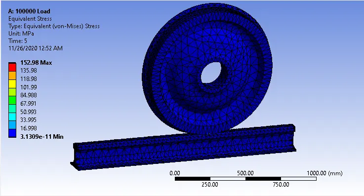
- Applied bearing load of 100000N as well as wheel should traslate 500mm in 5 steps each of 100 mm on rail.
Results:
2.Applied bearing load of 500000N as well as wheel should traslate 500mm in 5 steps each of 100 mm on rail.
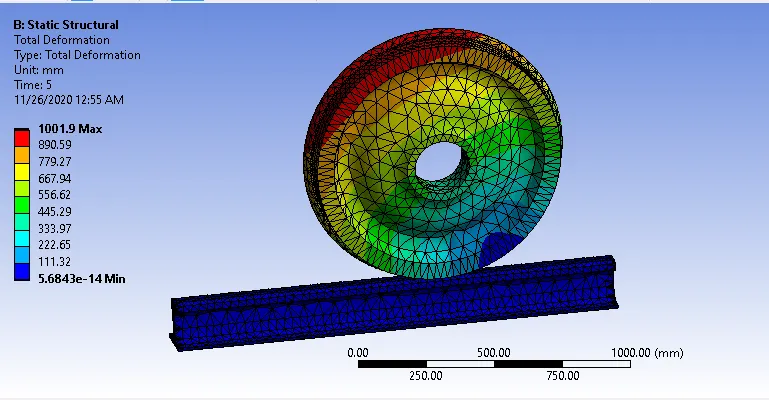
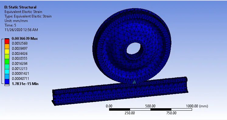
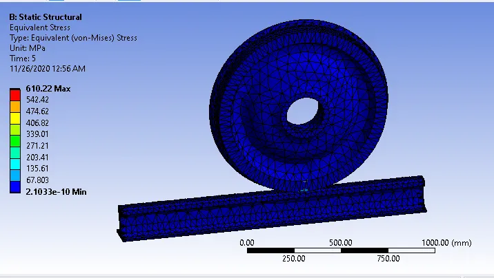
Results are Tabulated below:
| S.No | Parameters | 100000N Case | 500000N Case |
| 1 | No of Nodes | 24402 | 24402 |
| 2 | Max Equivalent stress(Mpa) | 152.98 | 610.22 |
| 3 | Max Equivalent Strain | 0.00096324 | 0.0036639 |
| 4 | Total Deformation(mm) | 1001.5 | 1001.9 |
| 5 | Minimum Life(min) | 68522 | 859.46 |
| 6 | Stress tool Min factor of saftey | 3.007 | 0.75382 |
| 7 | Fatigue tool Min factor of saftey | 0.5348 | 0.14126 |
Conclutions:
1. As mesh element size is same in both cases No of nodes are same.
2. Here we can clearly observe that equivalent stress has increased significantly with increase in Bearing load from 100000N to 500000N.Maximum stress is observed at point of contact between wheel and rail.
3.Maximum equivalent strain is comparitively more for 500000N bearing load than for 100000N bearing load.
4.Total Deformation is almost same in both cases.
5.Minimum life for 100000N bearing load is 68522 minutes and for 500000N bearing load is 859.46 min . Here we can also see that Life decreases drastically as bearing load increases.
6.As per stress tool mimimum factor of saftey for 100000N bearing load is 3.007>1 which is very safe but for 500000N case is 0.75382<1 which is not safe.
7. As per Fatigue tool mimimum factor of saftey for 100000N bearing load is 0.5348<1 which is not safe and for 500000N case is 0.14126<1 which is not safe.
CASE 2: IMPLEMENTATION OF USER DEFINED FUNCTION FOR MAX. TOTAL DEFORMATION:
User Defined function means with the help of mathematical expression we need to find our required results.Now we are trying to find results for Maximum total deformation using a mathematical expression. Different headers like U for Deformation, S for stress and EPTO for total strain etc are required to be used in UDF.
In analysis directional deformations are calculated at all the nodes in x,y,z directions. Total directional deformation in X direction is the sum of all nodal deformations in that particular direction.
Total Deformation is the Vector sum of Total directional deformations of X,Y and Z.
Total Deformation=`square root`(UX^2+UY^2+UZ^2)
where
UX is Deformation in X direction.
UY is Deformation in Y direction.
UZ is Deformation in Z direction.
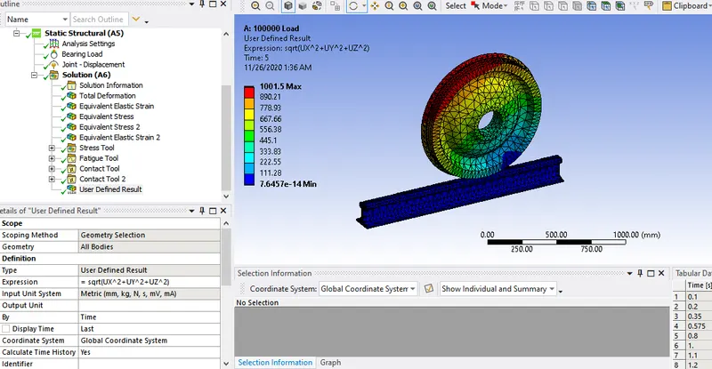
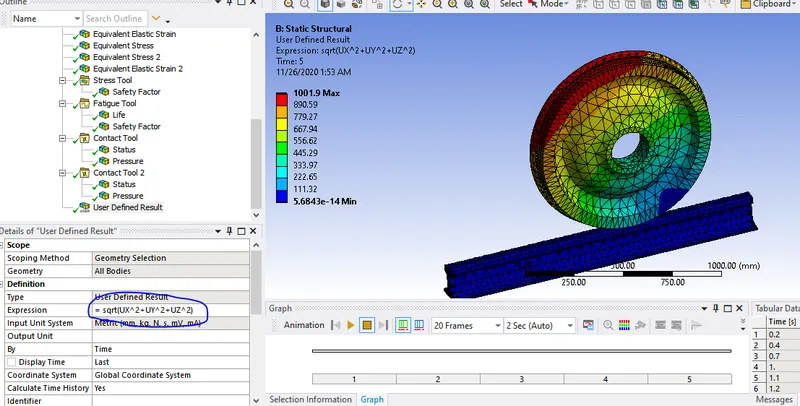
Conclusion:
It is concluded that results of UDF for Max total deformation matched with the inbuilt results calculated by simulaton.