Week 2 Railwheel and Track
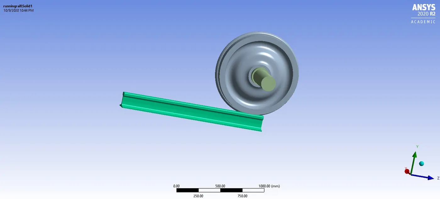
OBJECTIVE: To perform static structural analysis on the given railwheel and track setup for different bearing load conditions and to compare the results such as total deformation , equivalent stress and life under the loads respectively.
CASE 1 SETUP AND EXECUTION PROCEDURE :
In this case , the simulation and analysis is done for the wheel displacement of 500 mm along the track with 100,000 N bearing load on the shaft. First the results are attached for a bearing load of 100000 N and next for 500000 N .
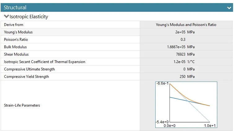
structural steel is the material used for all the parts of the model.
specifications of the material:
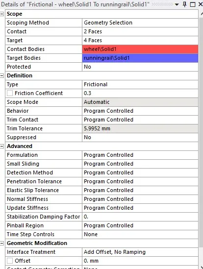
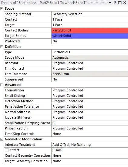
contact between the wheel and track and then the wheel and shaft are defined as follows ;
Joints included:
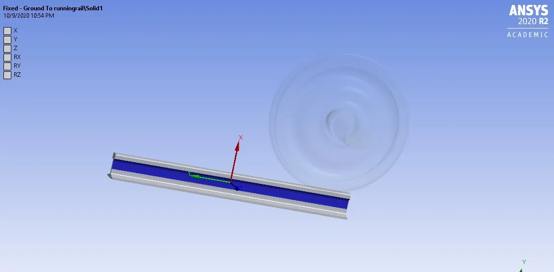
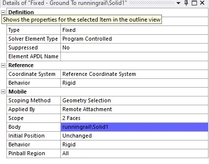
The track has a fixed joint defined as follows,
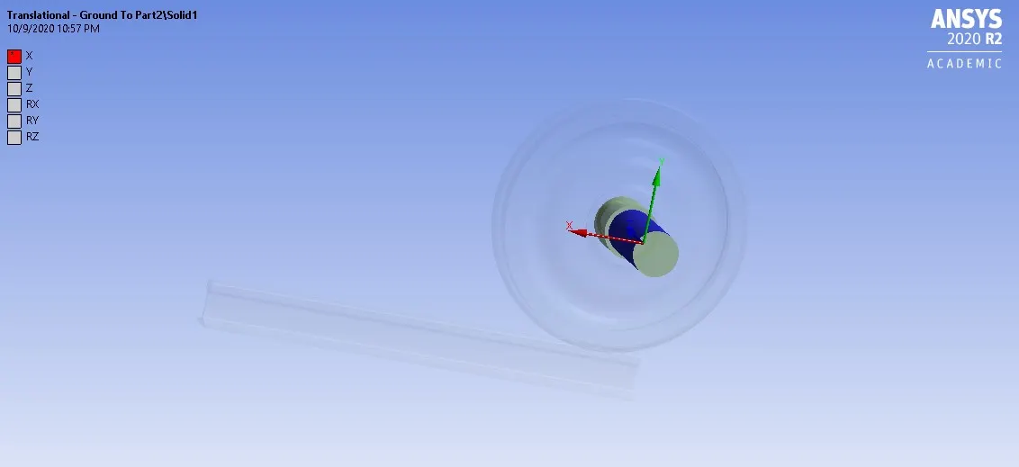
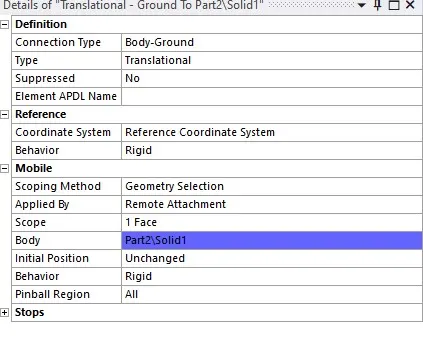
The shaft has a translational joint with the following specifications;
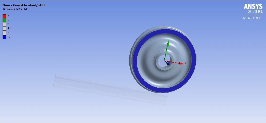
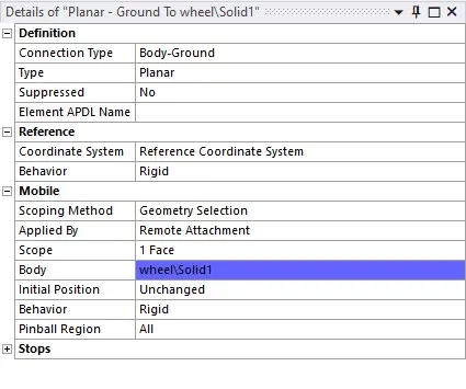
In order to make the wheel to remain on the same plane during the general body motion, a planar joint is defined over it as follows,
MESHING:
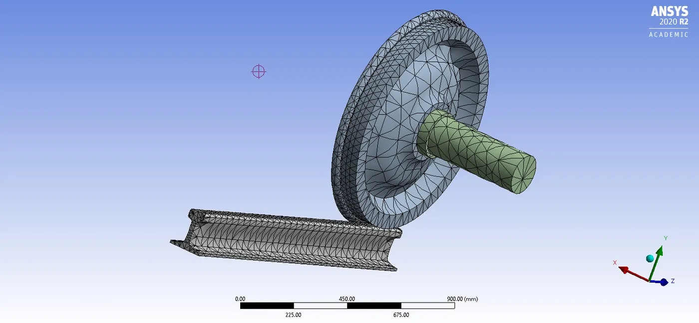
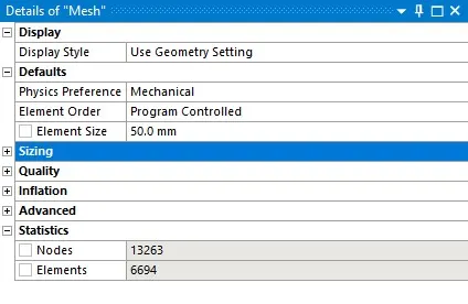
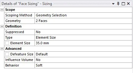
Meshing is done with element size as 50mm, but in the areas of contact the mesh seems to be too coarse thus including face sizing at these regions alone. The face sizing mesh element size is 35mm.
ANALYSIS SETTING:
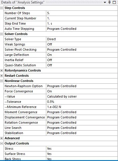
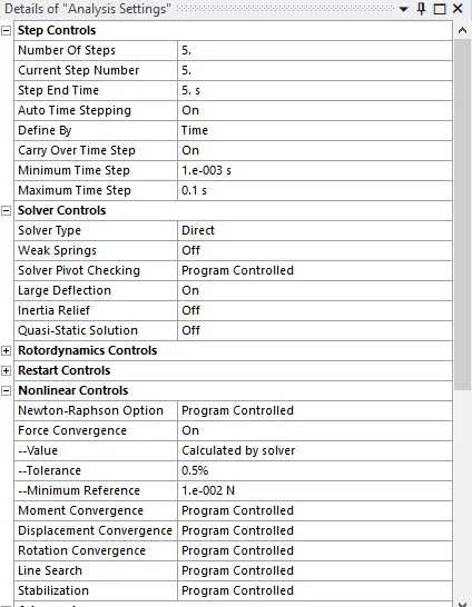
5 steps are assigned for the simulation with 100 mm displacement in every step.
setting for the first step:
setting for steps 2 to 5:
LOADS:
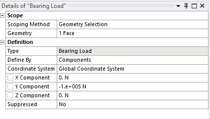
Bearing load of 1*e+005 N is applied on the shaft over the inner surface of contact of the wheel.
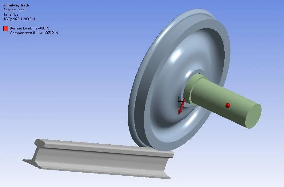
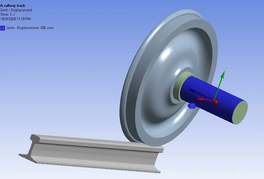
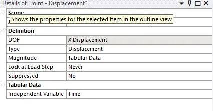
Displacement in x direction is defined for the shaft.
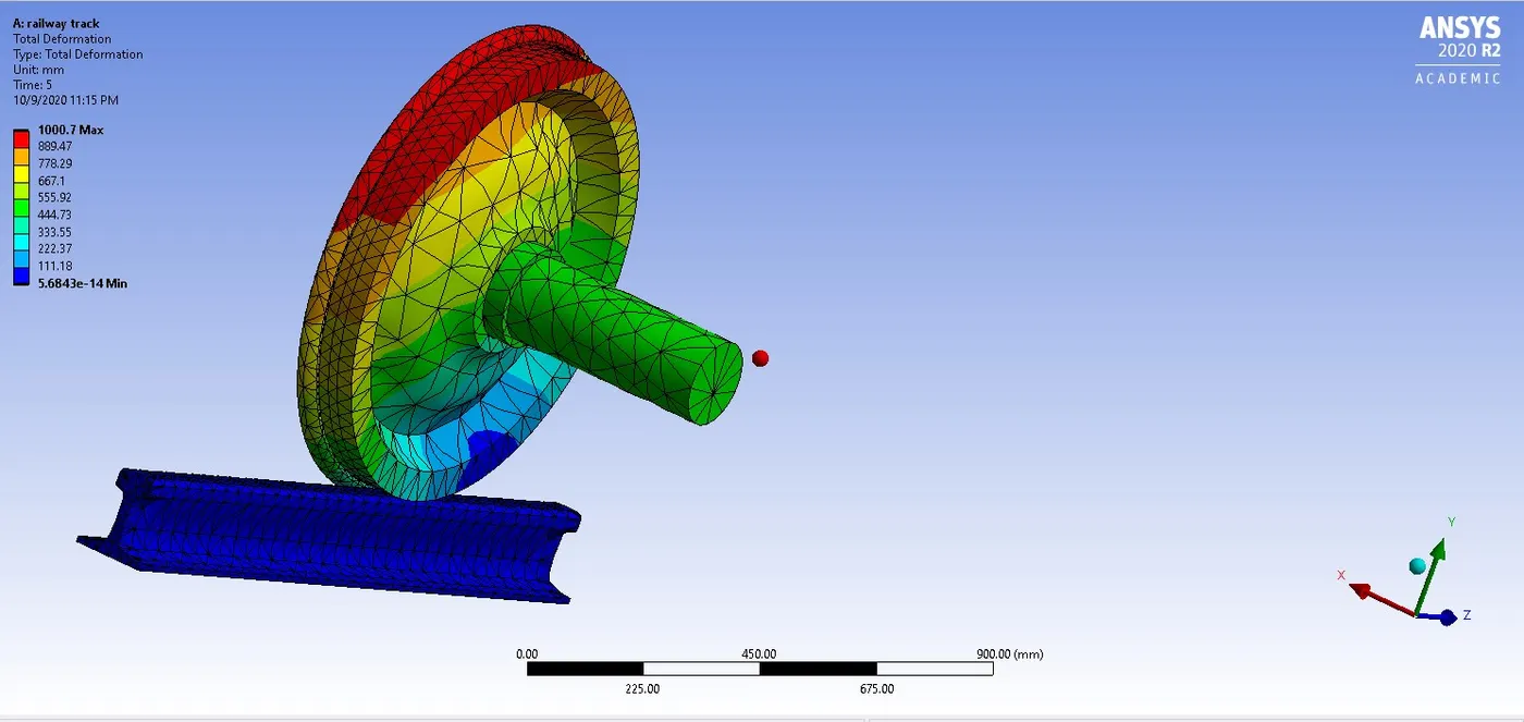
RESULTS FOR THE CASE: FOR BEARING LOAD OF 100000 N.
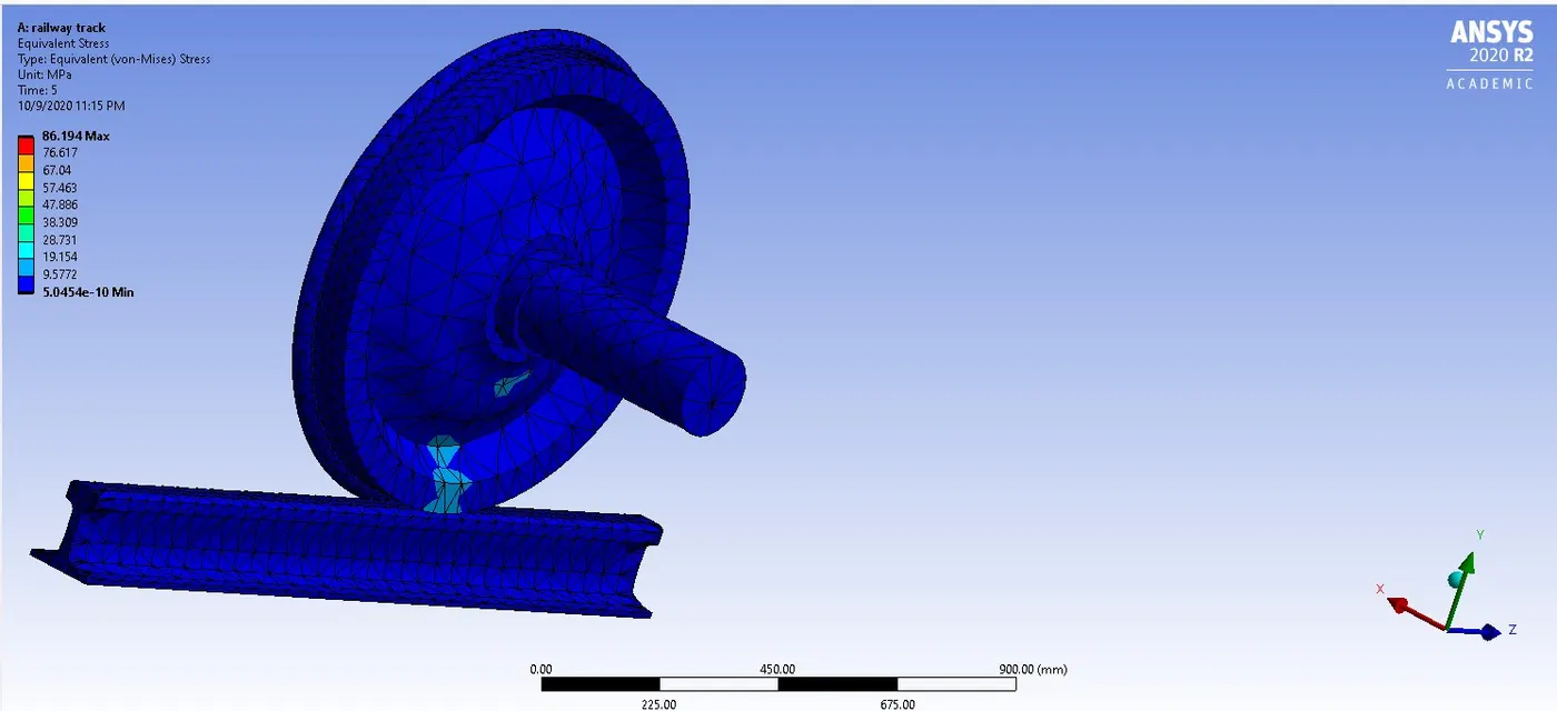
| RESULT | MAX VALUE | MIN VALUE |
| TOTAL DEFORMTION(mm) | 1000.7 | 5.6843e-14 |
| EQUIVALENT STRESS(MPa) | 86.194 | 5.0454e-10 |
FOR BEARING LOAD OF 500000 N :
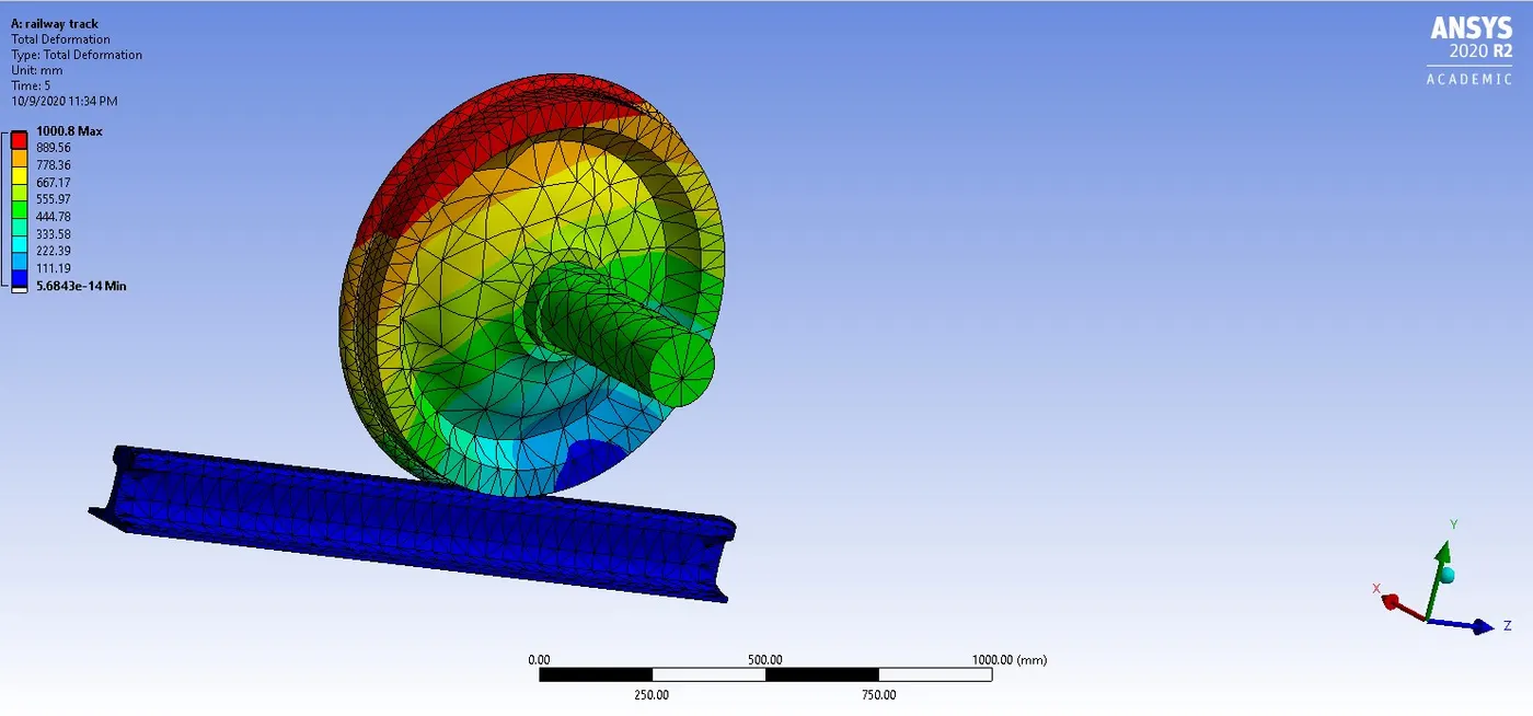
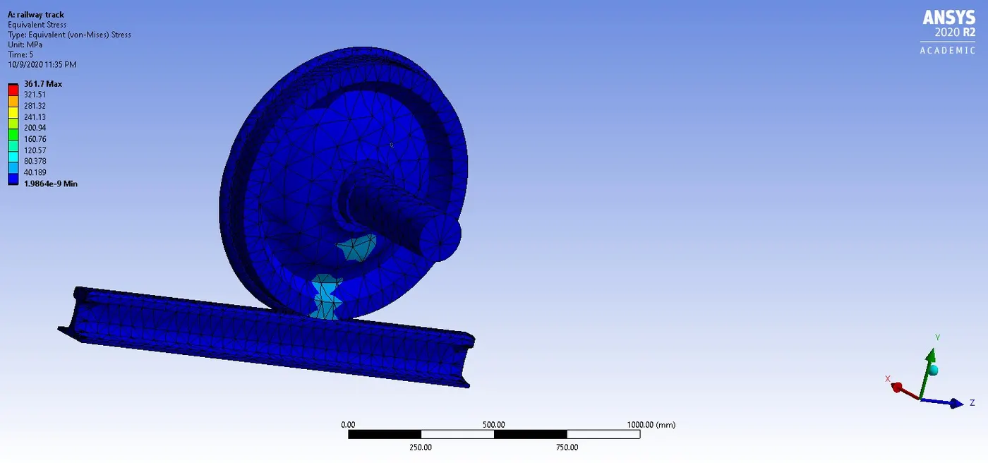
| RESULT | MAX VALUE | MIN VALUE |
| TOTAL DEFORMATION(mm) | 1000.8 | 5.6843e-14 |
| EQUIVALENT STRESS(MPa) | 361.7 | 1.9864e-9 |
we can observe tha for the given case 1 , for both the bearing loads the total deformation remains more or less the same but there is a huge hike in the equivalent stress in the 500000 N bearing load. This is an expected observation which is quite obvious as the bearing load is responsible for the stress generated on all the parts in contact.
CASE-2:
In this case we are using an user defined result for finding total deformation of the full setup and comparing with the analysis simulation result.
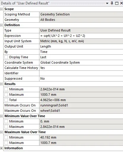
the above input expression is used to compute total deformation. solving this yields;
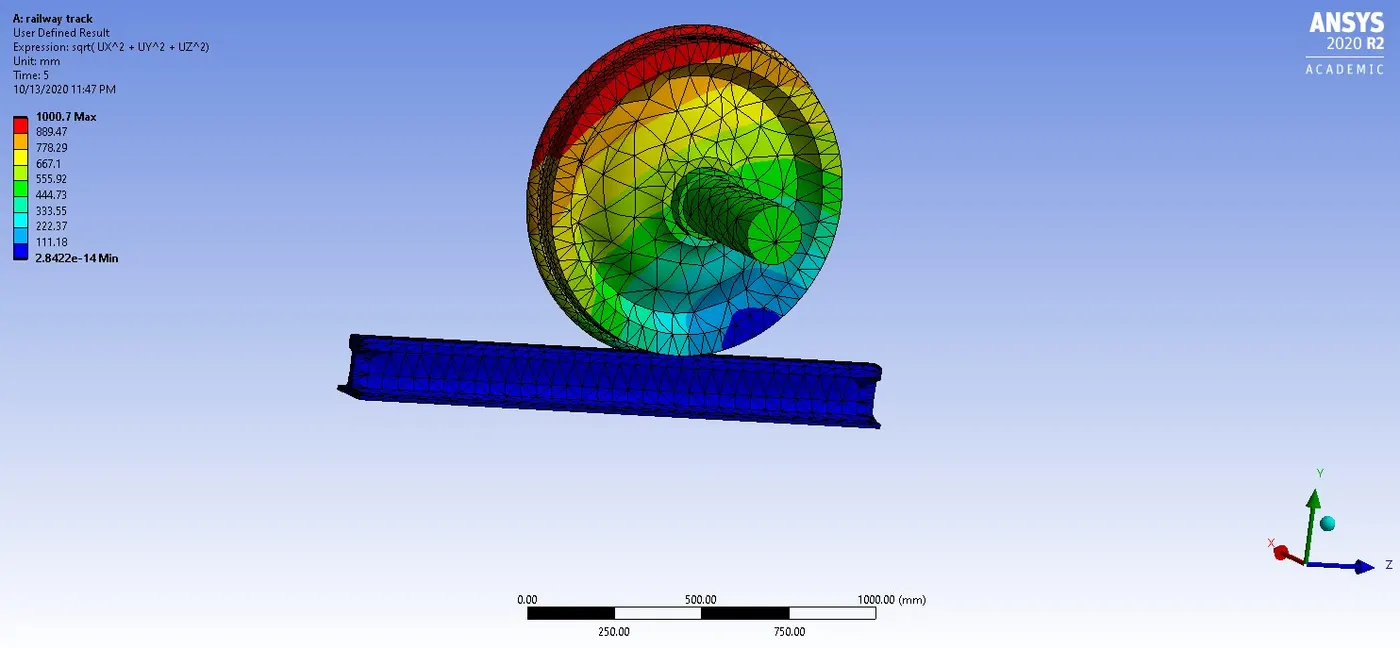
Thus we can observe here that the user defined result output is very similar to the simulation result for the total deformation.