Week 2 Railwheel and Track
Aim of the Analysis:
Case 1: Multiply the bearing load by 5 times and compare the results with the load of 100000 N (As done in week 2 video). Compare the Total Deformation, Equivalent stress and the life under both the loads
Case 2: Implement a User defined result and calculate the Total Deformation from this result and check if it is the same as that obtained by the inbuilt result by ANSYS for a load of 100000 N.
Objective:
With Rail and wheel analysis we will find the axle loading comes on the bearing of the wheel with other factor for wheel and rail like Total Deformation , Equivalent Stress and Strain in the Rail and wheel contact.
Due to dynamic condition like running like wheel on the track with heavy load coming on it in exterme condition this analysis will helps in the understand and its effect of the wheel geometry and bearing load. As wheel profile is machined considering to match the track profile to ensure the proper interaction. if interaction is not proper than it may cause increase in rolling resistance, reduce energy efficiency and may even cause a derailment with this analysis we can determine the different parameter and their causes.
The wheel have a conical or cylindrical geometry which is the primary menas of keeping the trains motion aligned with the track with wheel having one flange one side to keep the wheel inline with motion.
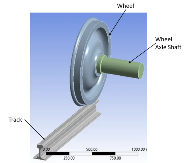
Analysis Parts used & Material Details:
|
Details |
Structural Steel |
|
Density Kg/m3 |
7850 |
|
Tensile Yield Strength (MPa) |
250 |
|
Tensile Ultimate Strength (MPa) |
460 |
|
Possion Ratio |
0.3 |
|
Young's Modulus(MPa) |
2e+05 |
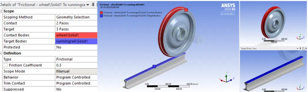
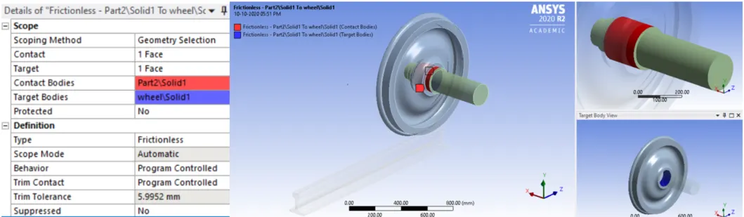
Connection Details:
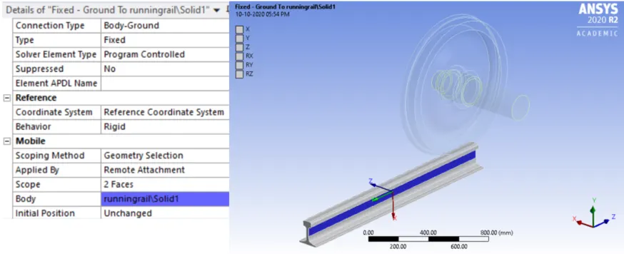
Joints Details:
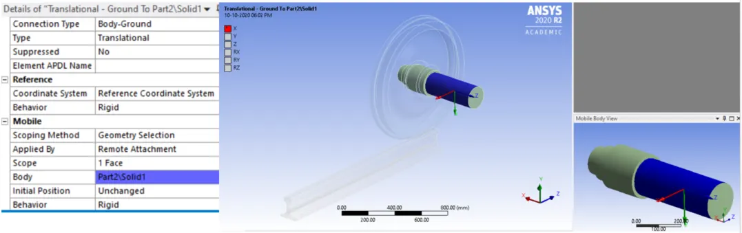
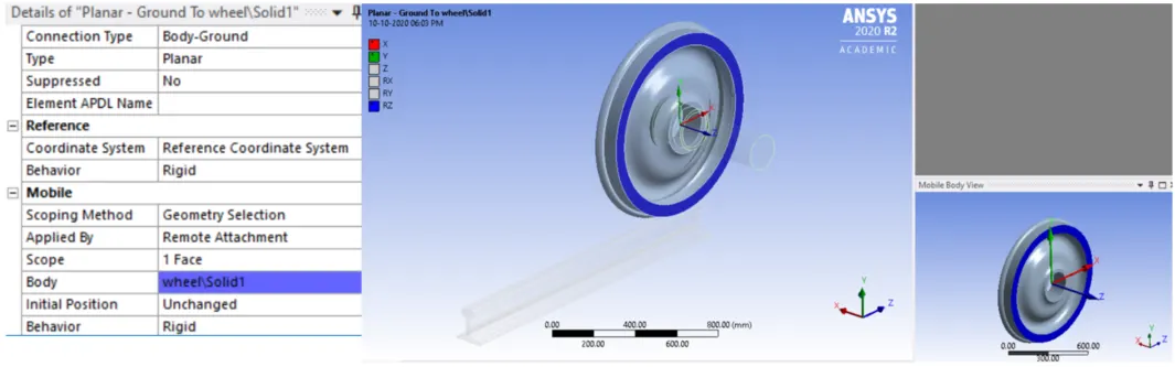
Mesh Details:
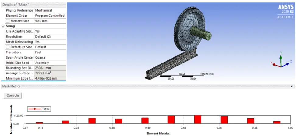
Meshing is of the wheel and track with below detail
Mesh Element size: 50 mm.
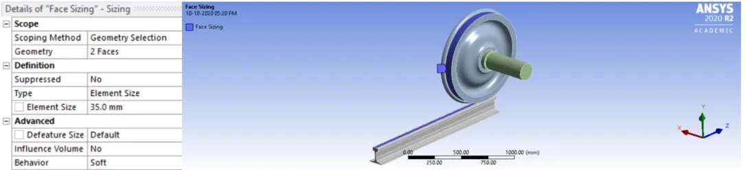
Face Sizing Mesh Details:
Face Mesh Element size: 35 mm.
Analysis Setting & Output Control Details:
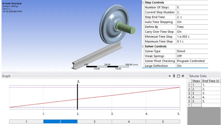
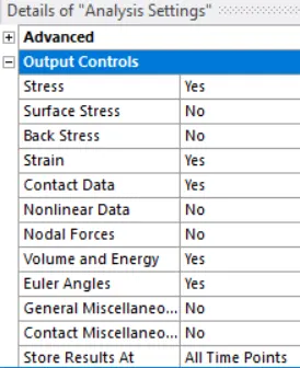
Case 1: Multiply the bearing load by 5 times and compare the results with the load of 100000 N (As done in week 2 video). Compare the Total Deformation, Equivalent stress and the life under both the loads
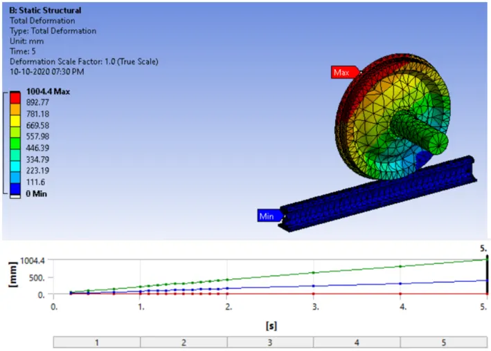
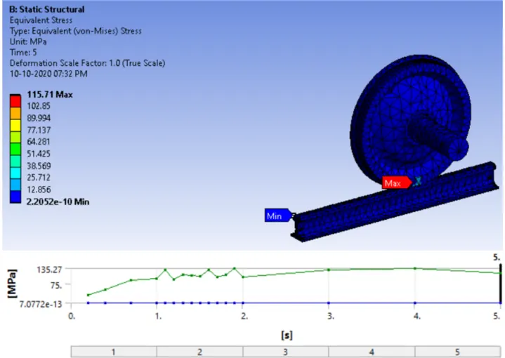
Below Result with Bearing load of 10000 N for Total Deformation, Equivalent Stress and Fatigue life :
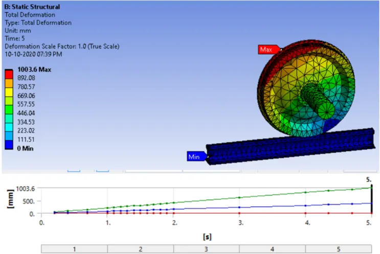
Total Deformation with Bearing load: 10000 N
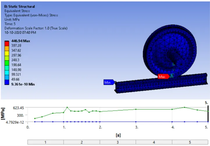
Equivalent Stress (Von Mises):
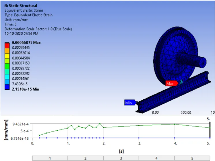
Equivalent Elastic Strain:
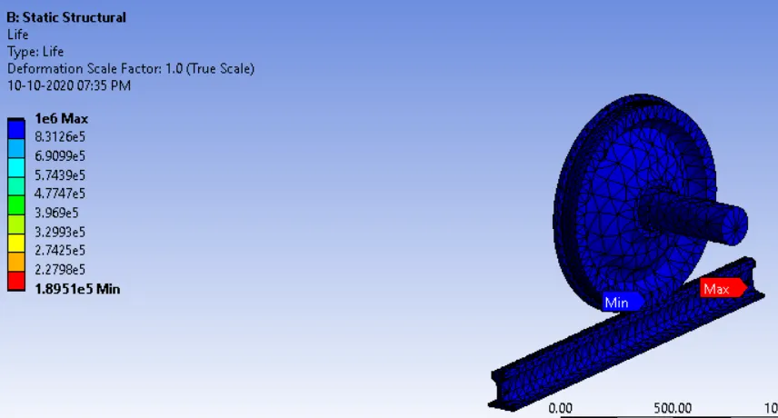
Fatigue Life(Cycles):
Below Result with Bearing load of 50000 N for Total Deformation, Equivalent Stress and Fatigue life :
Total Deformation with Bearing load: 50000 N
Equivalent Stress (Von Mises):
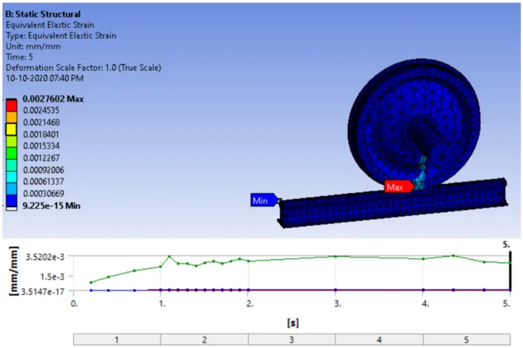
Equivalent Elastic Strain:
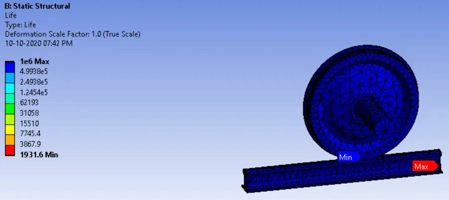
Fatigue Life(Cycles):
Conclusion:
Comparing the two results considering two bearing load values like 10000 N & 50000 N. The values are tabulated:
Parameter:
| 10000 N | 50000 N | |
| Total Deformation | 1004 | 1004 |
| Equivalent Stress (Von Mises) | 115.71 | 446.94 |
| Equivalent Elastic Strain | 6.68e-10 | 2.76e-9 |
| Fatigue Life (Cycle) | 1.89e5 | 1931.6 |
With above result we can conclude that with increasing bearing load the stress and life decreases.
Case 2: Implement a User defined result and calculate the Total Deformation from this result and check if it is the same as that obtained by the inbuilt result by ANSYS for a load of 100000 N.
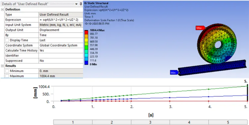
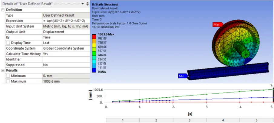
With implementing the user defined to know the total deformation for the directional deformation along the three principal axes. A vector in cartesian coordinates are defined by coordinate
along the axis of X, Y and Z. Taking the three mutually perpendicular forces Ux, Uy and Uz to find the total deformation by √Ux2+Uy2+Uz2.
Total Deformation:
For 10000 N:
For 50000 N:
Conclusion:
Referring the above values from the user defined result are same like the standard Total deformation values in both cases.
| 10000 N | 50000 N | |
| Total Deformation | 1004 | 1004 |
| Total Deformation using User Defined Result | 1004 | 1004 |
For other factor determination on the wheel and track like Equivalent Stress 2, Equivalent Elastic Strain 2, Contact Tool Pressure, Status, I have attached the Ansys file in the archieve format for better understanding.