Week 2 Railwheel and Track
Objective: perform the simulation in static structural analysis in ANSYS workbench on Rail-wheel and track with 1e+5 N and 5e+5 N load and compare deformation, stress strain and fatigue life of the component. In case 2 we have to compare user define result with inbuilt result in ANSYS.
Case 1:
To perform static structural analysis on rail-wheel and track system we used structural steel material, the mechanical properties of the material are given below
Density : 7.85e-06 kg/mm³
Isotropic Secant Coefficient of Thermal Expansion : 1.2e-05 1/°C
Young's Modulus: 2e+05 MPa
Poisson's Ratio: 0.3
Bulk Modulus: 1.6667e+05 MPa
Shear Modulus: 76923 MPa
Tensile Yield strength : 250 MPa
Compressive Yield strength : 250 MPa
Tensile Ultimate strength : 460 MPa
Isotropic Thermal Conductivity : 0.0605 W/mm·°C
Specific Heat Constant Pressure: 4.34e+05 mJ/kg·°C
Isotropic Resistivity: 0.00017 ohm-mm
Isotropic Relative Permeability: 10000
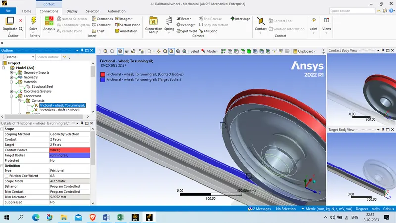
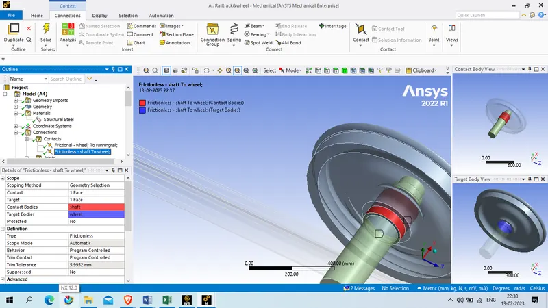
A frictional contact is deployed between wheel and track with co-efficient of friction as 0.3 and frictionless contact is is deployed between shaft and wheel.
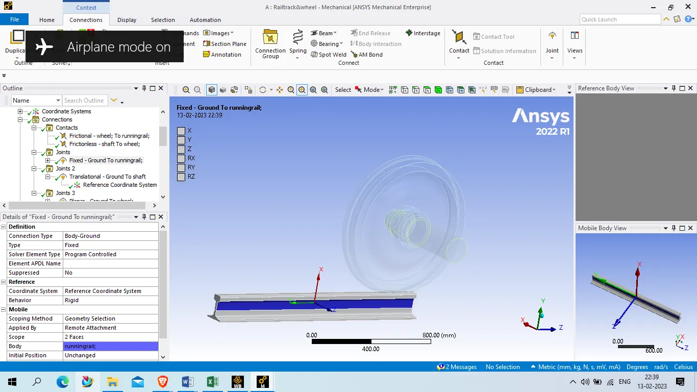
fix joint is deployed at track to avoid all type of movement that is all roational and translational movement .
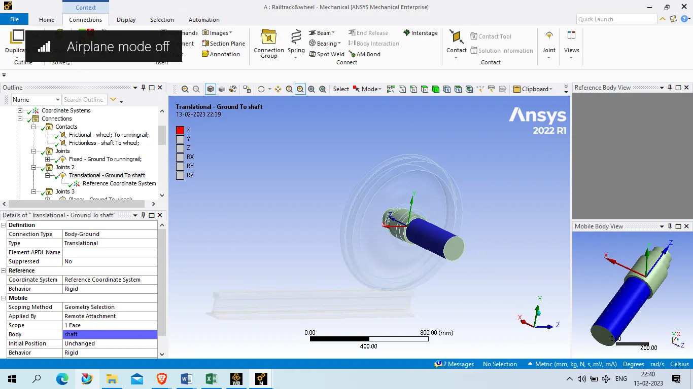
translational joint is deployed at shaft so that it can only move in x direction.
and planner joint is deployed at face of sheel such that it can only rotate abut z direction and translate only in x and y direction
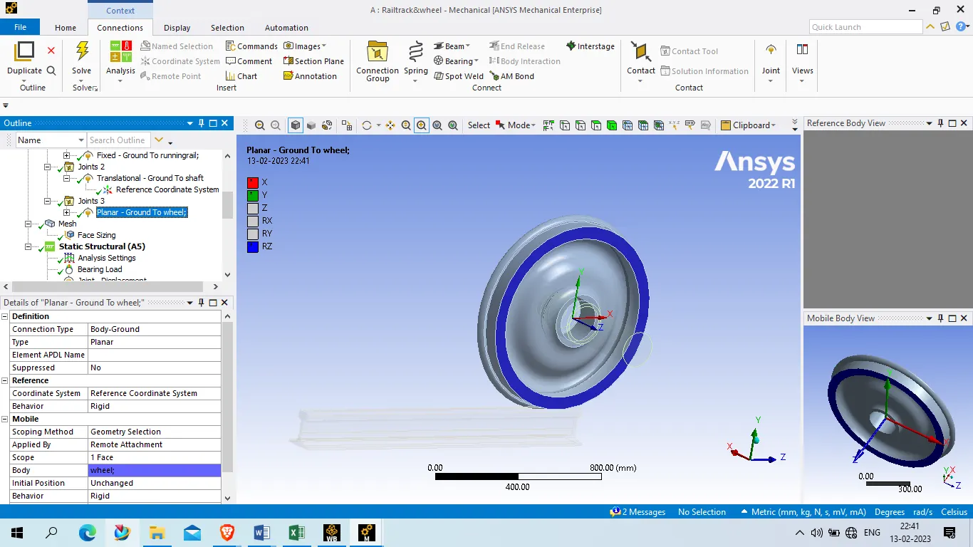
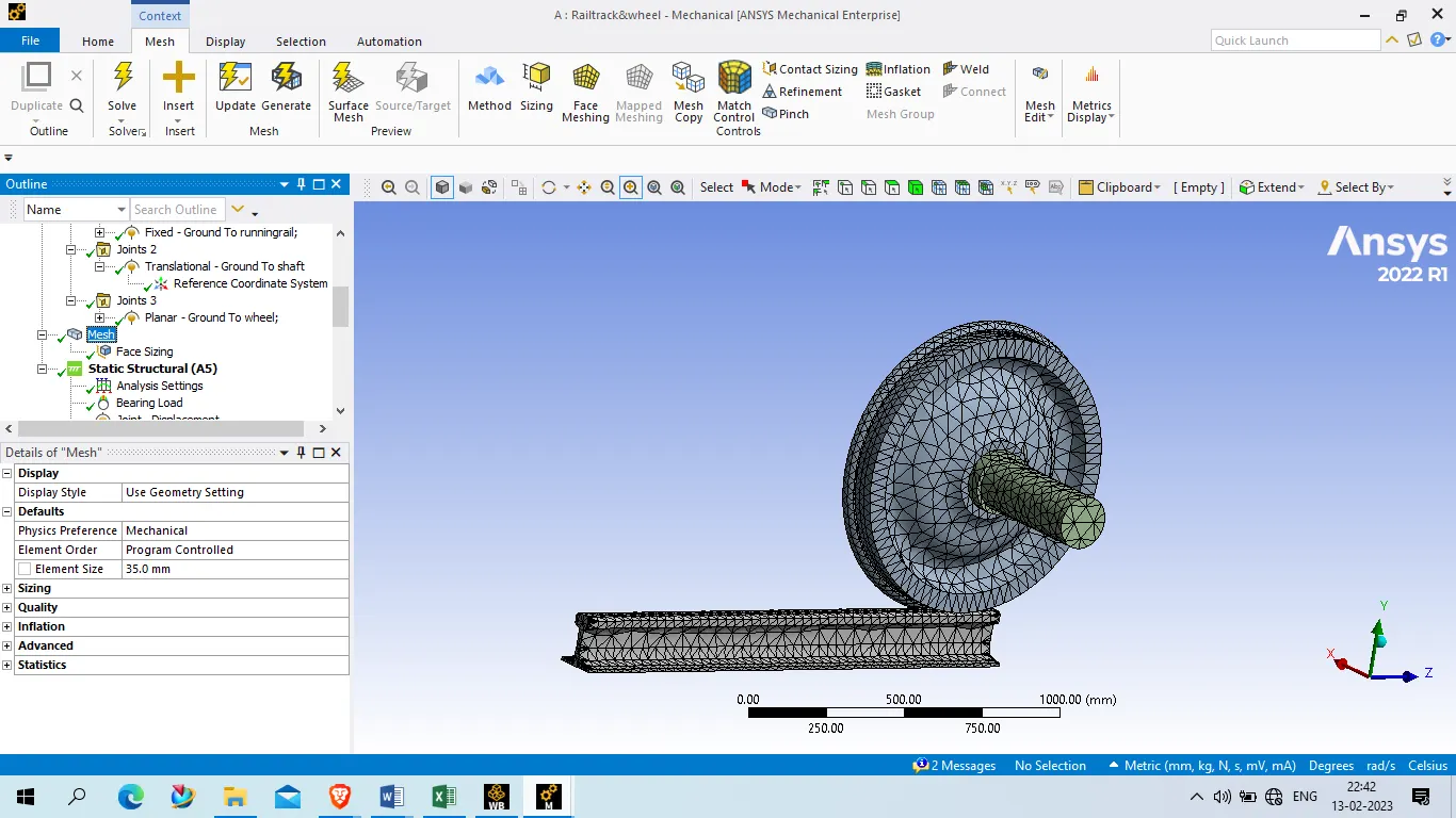
for mesh , we had given mesh element size of 35 mm and face which are in contact while operation like track and wheel face at also with 35 mm
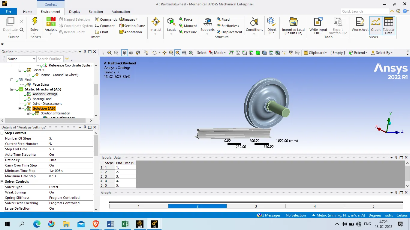
structural analysis setting is done with 5 step
in which 1st step is done with auto stepping size- program controll, large deflection -on , solver type - Direct.
outout controll- select all parameters as "YES', force conversion -0N.
and for 2nd to 5th step- auto time stepping -on, define by- time, carry over time step- on, minimum time step -1e-3 and max time step-0.1, solver type- direct, force conversion- on and output controll- all parameters set as"YES".
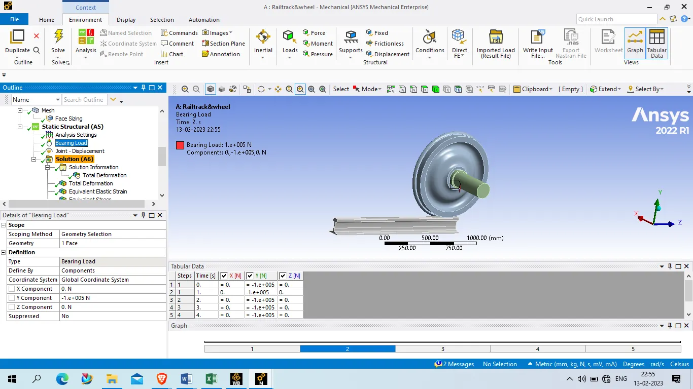
to define load, we delpoyed bearing load of 1E+5N on the inner surface of wheel which is in contact with the shaft.
also displacement joint deployed on shaft with X direction displacement 500 mm , 100 mm at each step.
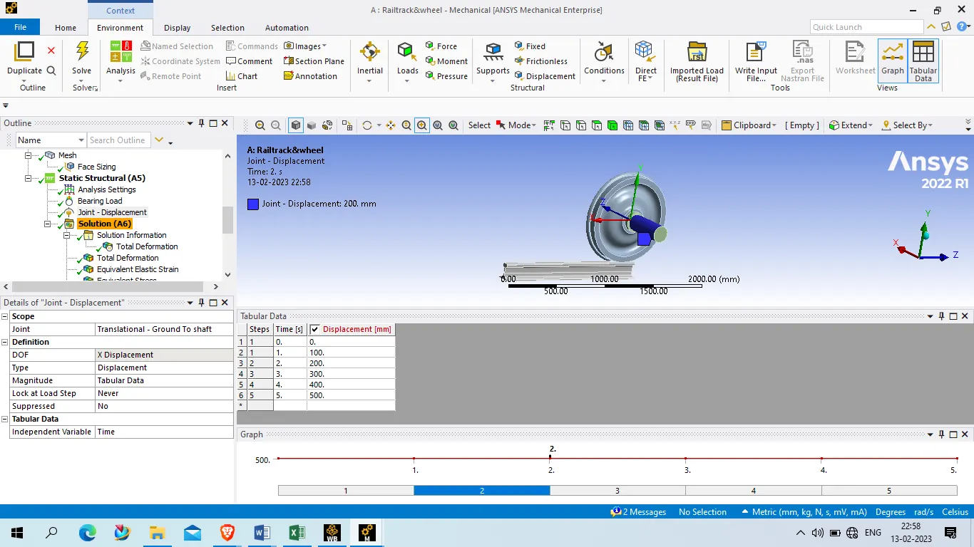
Picture :
Equivalent stress on all body :
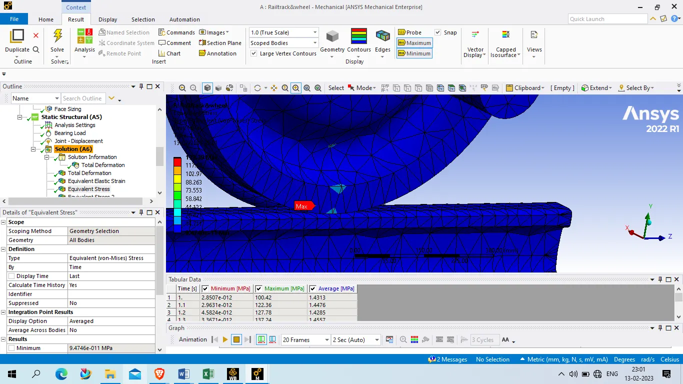
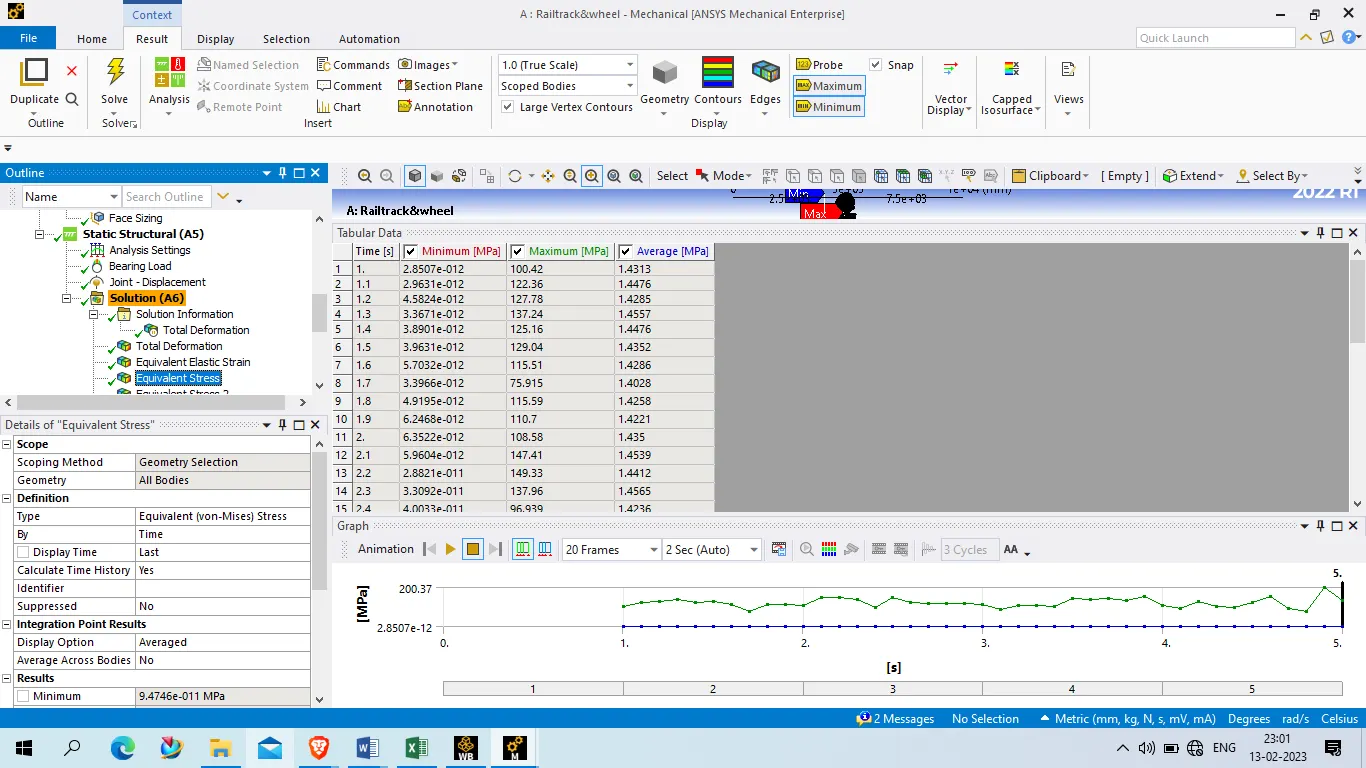
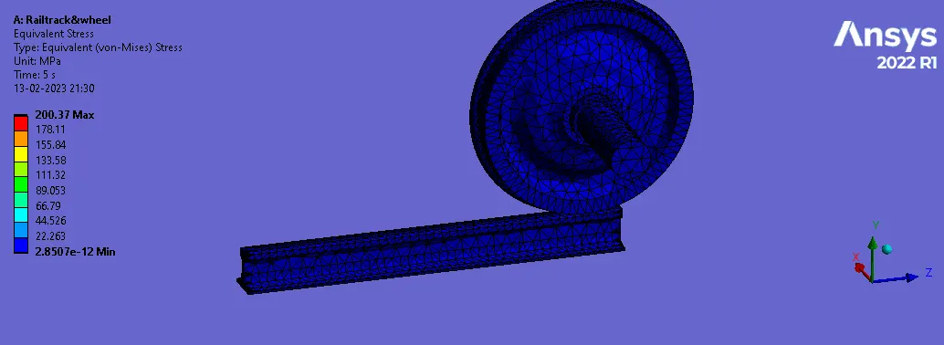
Equivalent stress on wheel
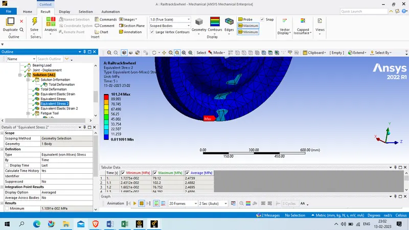

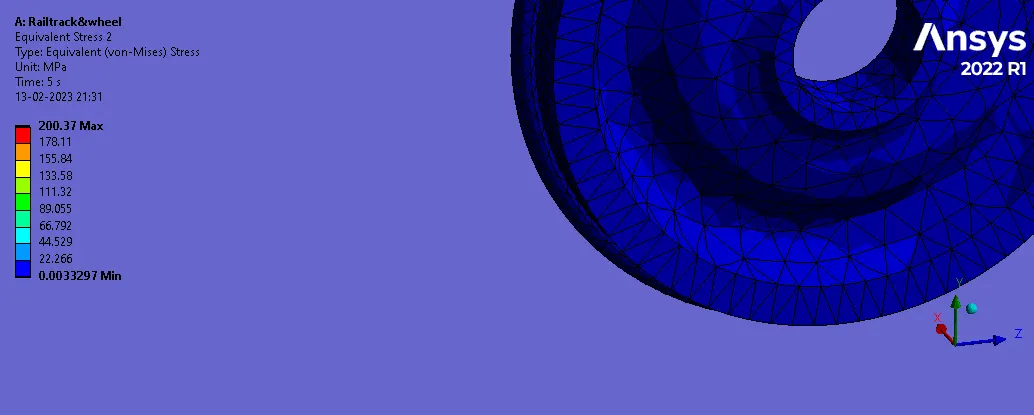
Equivalent strain on all body
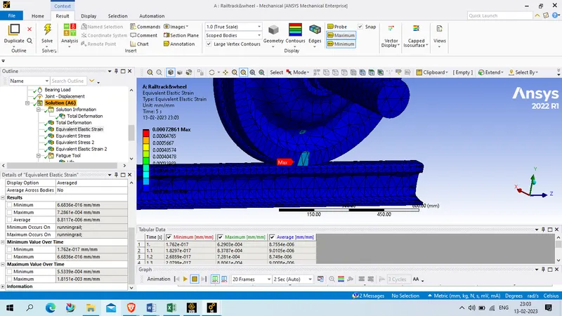
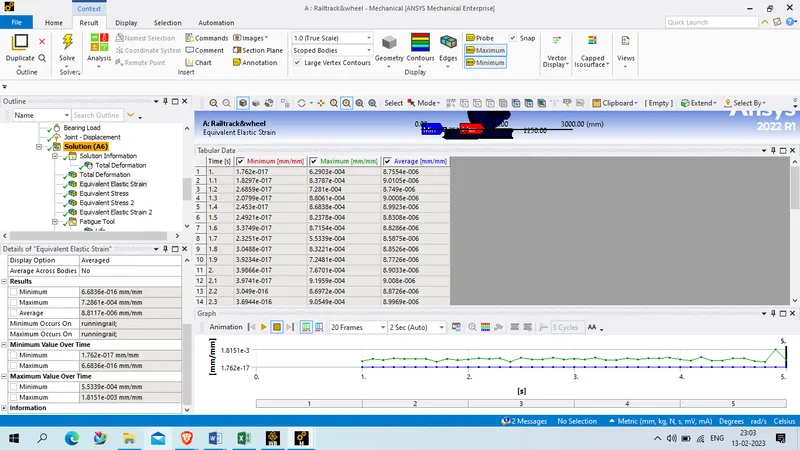
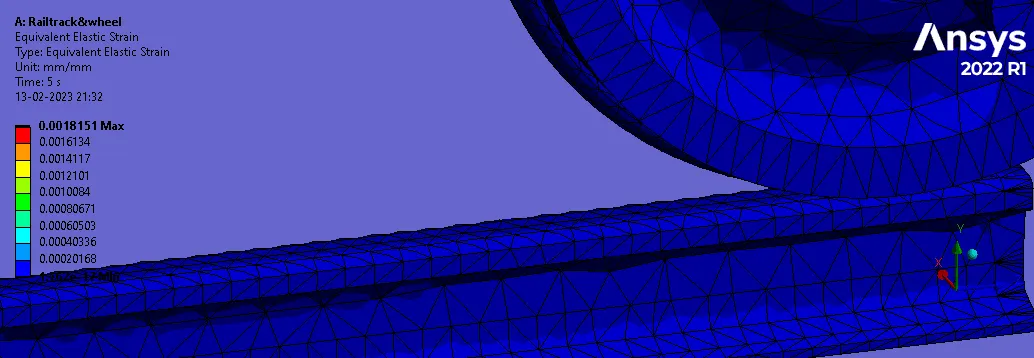
Equivalent strain on wheel
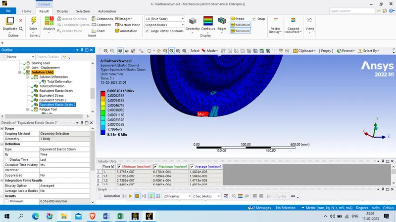
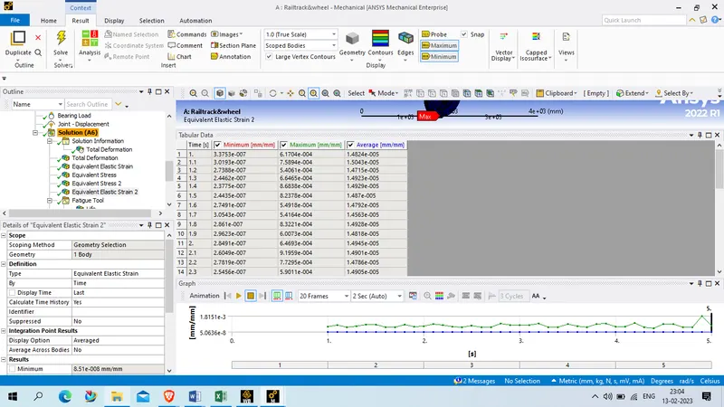
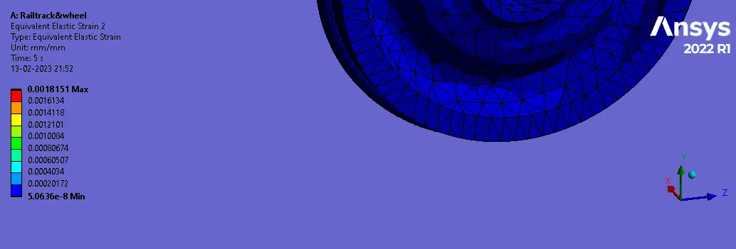
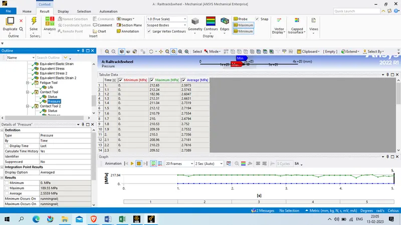
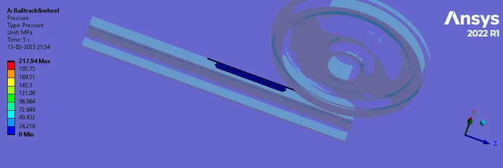
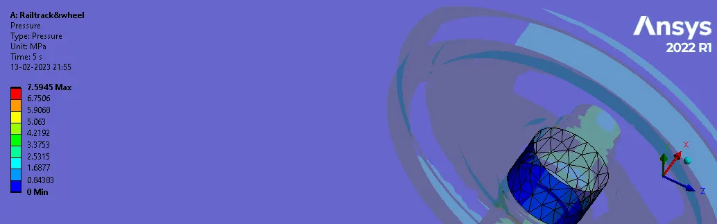
contact pressure : wheel to track
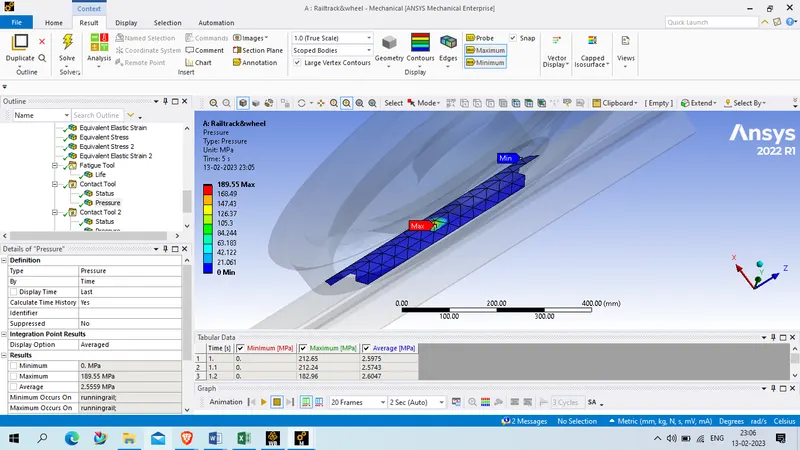
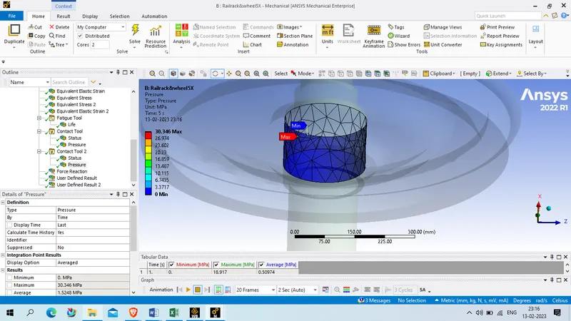
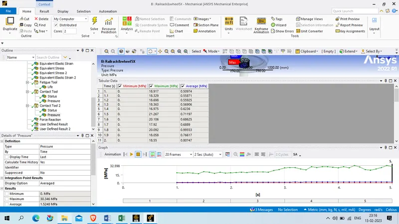
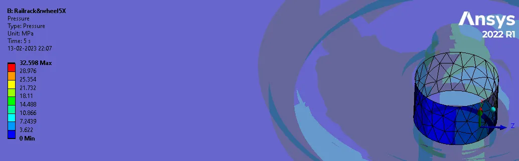
COntact pressure : shaft to wheel
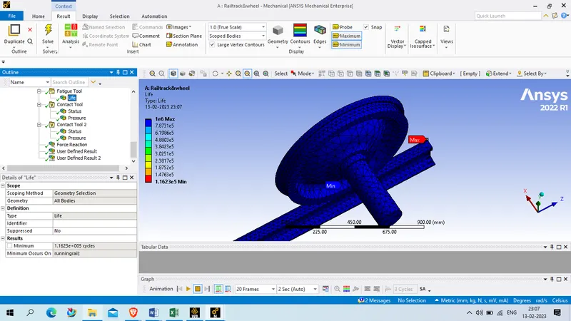
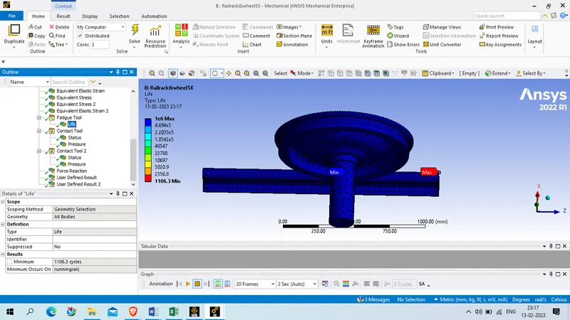
Fatigue life
Case 2 : Load 5E+5 N
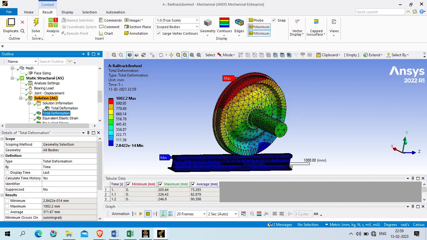
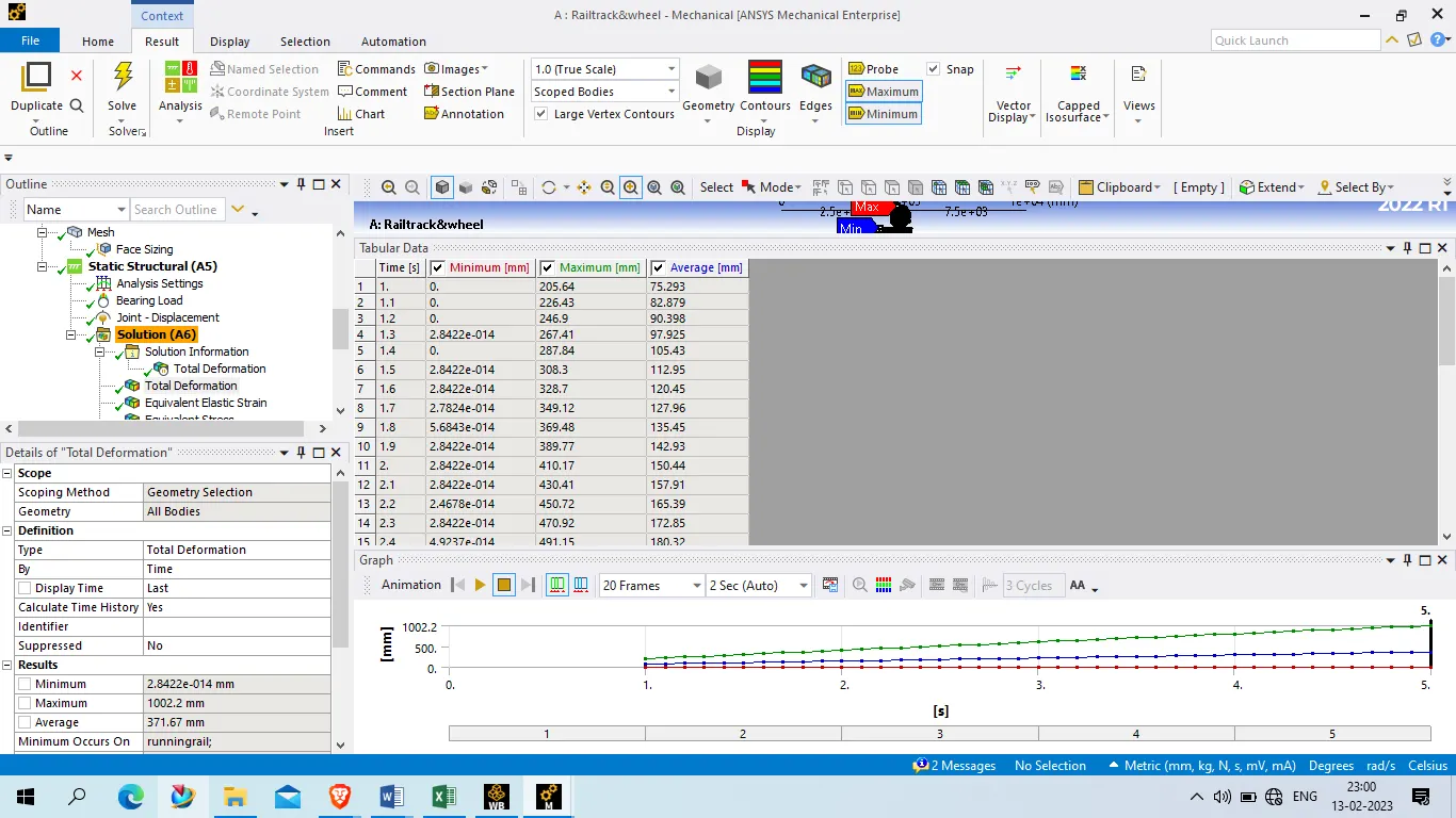
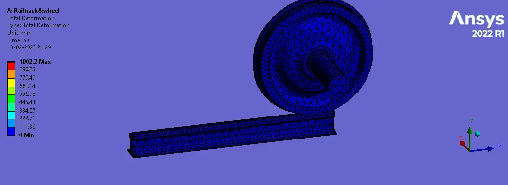
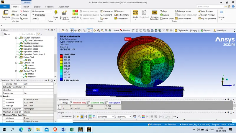
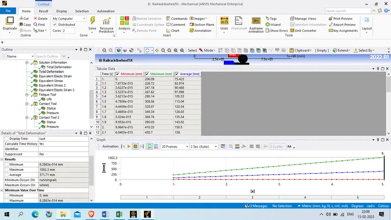
Total deformation
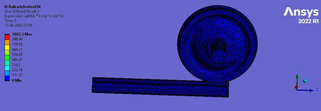
Equivalent stress to all body
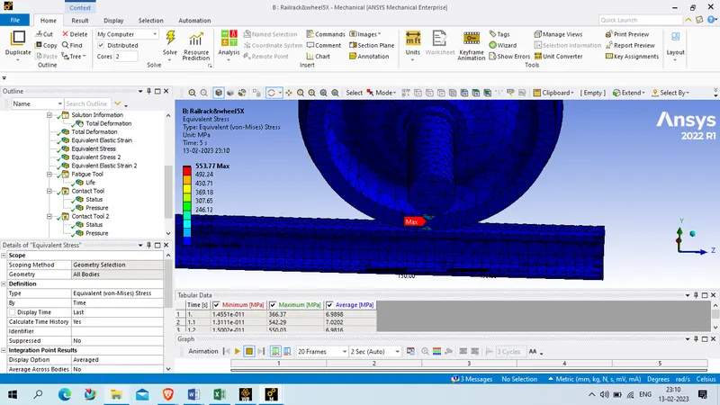
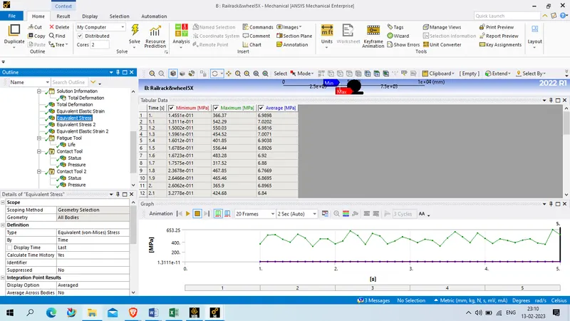
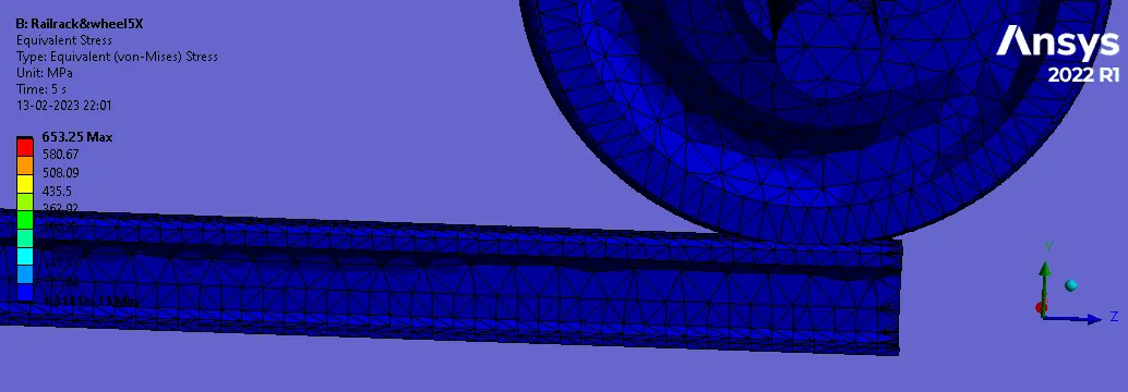
Equivalent stress on wheel
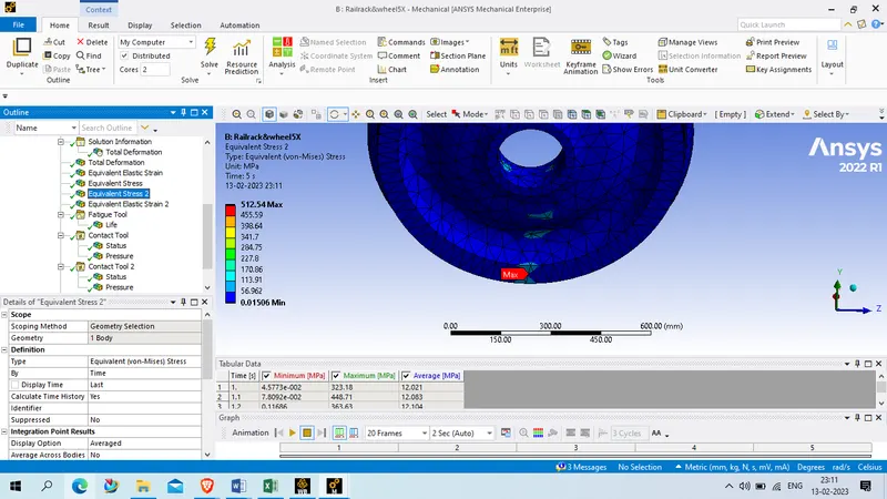
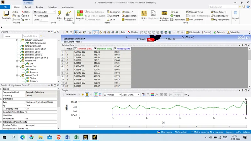
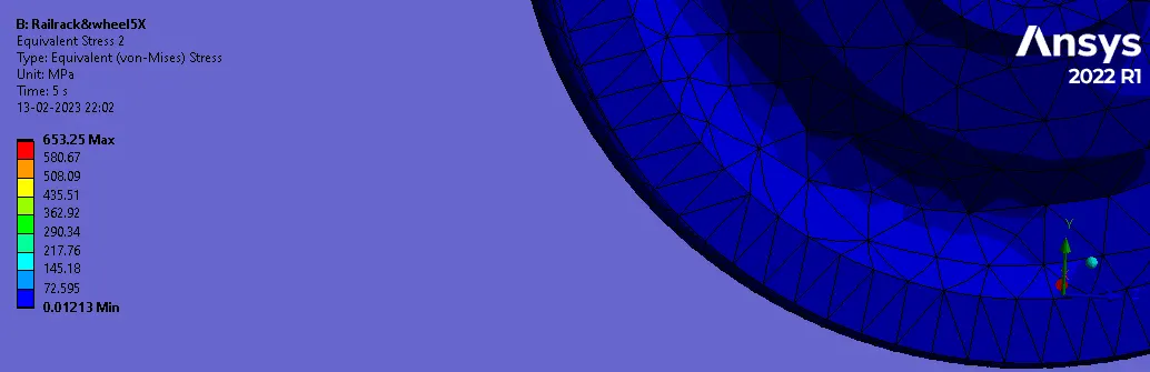
equivalent strain on all body
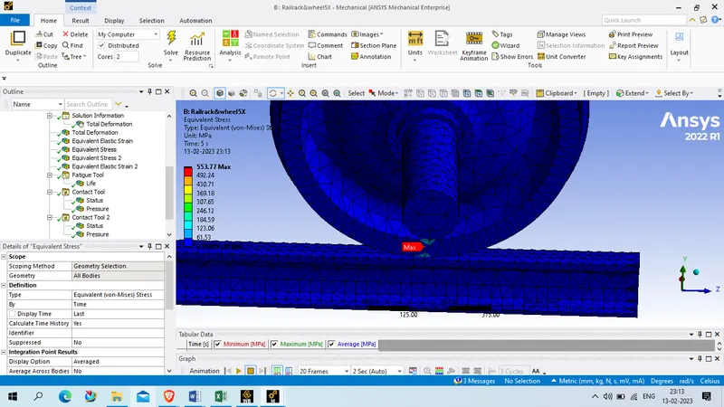
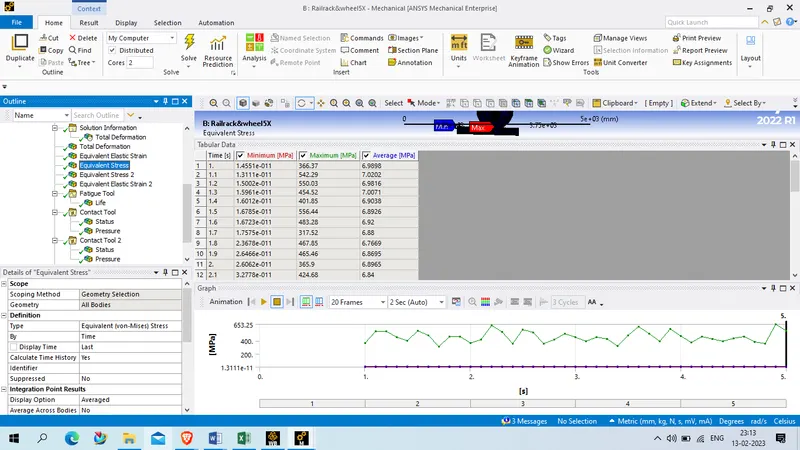
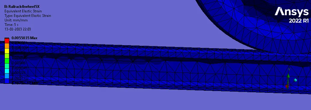
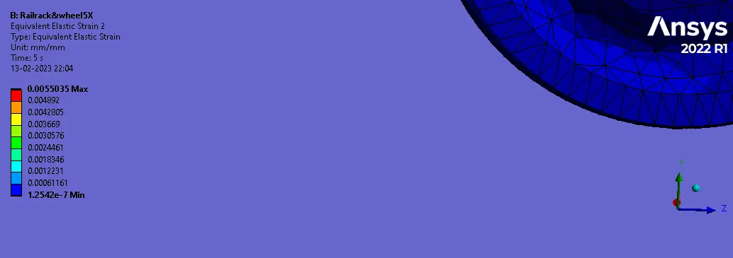
equivalent stress on wheel
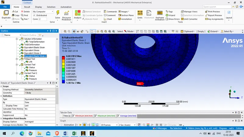
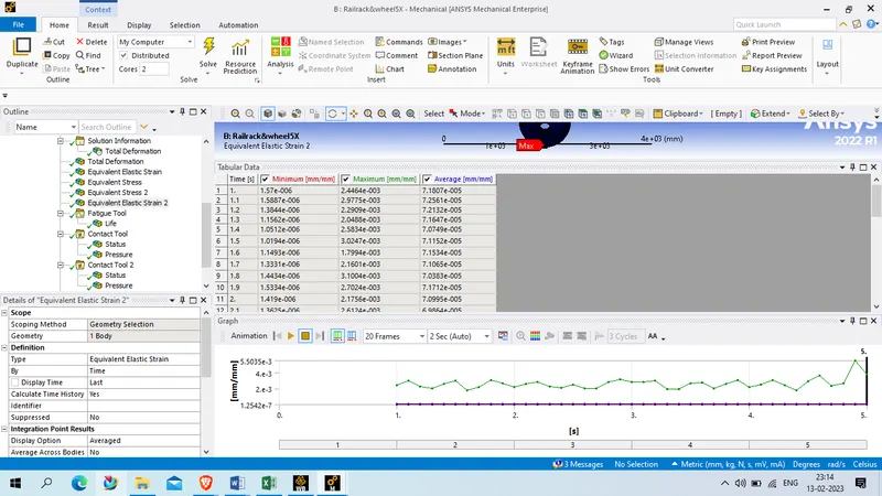
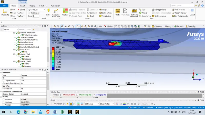
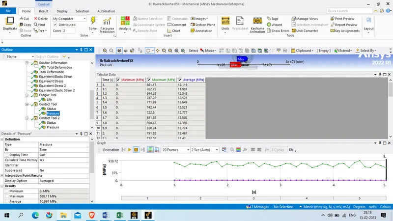
contact pressure : wheel to track
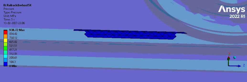
Contact pressure: shaft to wheel
Fatigue life
Result:
The total deformation in both cases are compared below
| Load (N) | time (s) | Minimum (mm) | Maximum (mm) | Average (mm) |
| 1.00E+05 | 5 | 2.84E-14 | 1002.2 | 371.67 |
| 5.00E+05 | 5 | 8.29E-14 | 1002.3 | 371.71 |
The quivalent stress on complete body in both cases are compared below
| Load(N) | time (s) | Minimum (Mpa) | Maximum )Mpa) | Average (Mpa) |
| 1.00E+05 | 5 | 9.47E-11 | 132.39 | 1.4425 |
| 5.00E+05 | 5 | 2.79E-10 | 553.77 | 6.7965 |
The equivalent stress on wheel in both cases are compared below
| Load(N) | time (s) | Minimum (Mpa) | Maximum )Mpa) | Average (Mpa) |
| 1.00E+05 | 5 | 1.11E-02 | 101.24 | 2.428 |
| 5.00E+05 | 5 | 1.51E-02 | 512.54 | 11.467 |
The equivalent strain on complete body in both cases are compred below
| Load(N) | time (s) | Minimum | Maximum | Average |
| 1.00E+05 | 5 | 6.68E-16 | 7.29E-04 | 8.81E-06 |
| 5.00E+05 | 5 | 2.29E-15 | 7.29E-04 | 8.81E-06 |
The equivalent strain on wheel in both cases are compared below
| Load(N) | time (s) | Minimum | Maximum | Average |
| 1.00E+05 | 5 | 8.51E-08 | 7.01E-04 | 1.45E-05 |
| 5.00E+05 | 5 | 1.31E-07 | 3.78E-03 | 6.88E-05 |
COntact pressurefrom wheel to track are compred below
| Load(N) | time (s) | Minimum(Mpa) | Maximum(Mpa) | Average(Mpa) |
| 1.00E+05 | 5 | 0 | 189.55 | 2.5559 |
| 5.00E+05 | 5 | 0 | 588.11 | 10.997 |
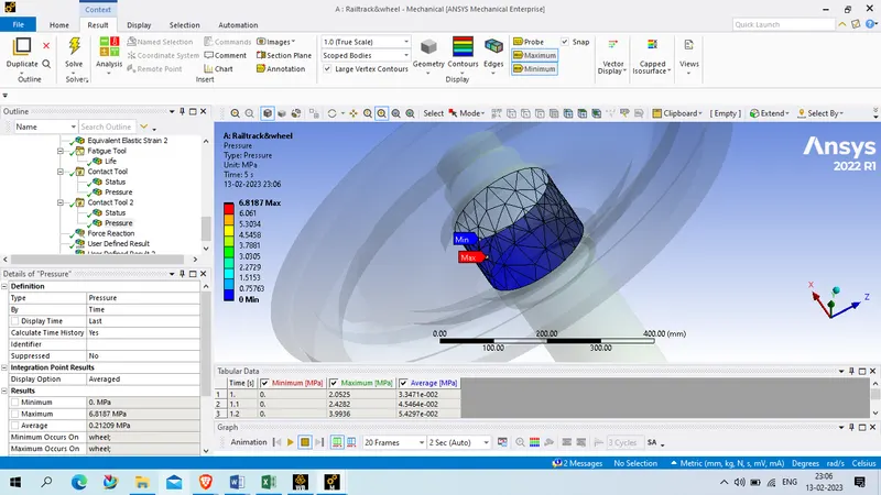
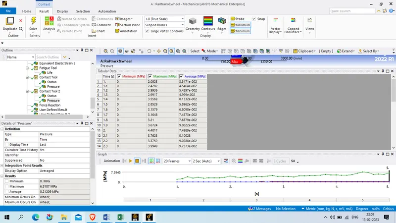
COntact pressure shaft to wheel in both cases are compared below
| Load(N) | time (s) | Minimum(Mpa) | Maximum(MPa) | Average(Mpa) |
| 1.00E+05 | 5 | 0 | 6.8187 | 0.21209 |
| 5.00E+05 | 5 | 0 | 30.346 | 1.5248 |
Fatigue life in both cases are compared below
| Load(N) | Life cycle |
| 1.00E+05 | 1.1623e+005 cycles |
| 5.00E+05 | 1106.3 cycles |
Conclusion:
On comparing the reesult in both cases that with load of 1E+5 N and 5E+5 N load, we found that their is no any change in maximum deformation which is same in both the cases as 1002.2 mm
on comparing stress in both the cases we found that on increasing the load stress also increase with respect to the load, on load of 1E+5 N the maximum stress was 101.24 MPa which increase to 553.77 MPa when load is increase to 5 time . and maximum stress occure on wheel near the contact point.
equivalent strain value also does not change with respect to load in this case.
the min fatigue life cycle in case of 1E+5 N load was 1.1623e+005 cycles which means it have infinte fatigue life when it loaded with on limited load which is 1E+5 N. whicle in case of 5 time load which is 5E+5 N load the fatigue life cycle of component was 1106.3 cycles , it means it obserbed low fatigue cycle component.
Case 2:
Total deformation is summision of each direction deformation , mathematically it can be expressed as
total deformation =square root of summision of square of each direction deformation
total deformation = sqrt(Ux^2+Uy^2+Uz^2)
Where,
Ux= deformation in x direction
Uy= Deformation in y direction
Uz= deformation in z direction
we check above equation in user define result in 1st case i.e. with load of 1E+5 N . we know that total deformation of inbuild system in ANSYS was 1002.2 mm
we define equitation and get the result
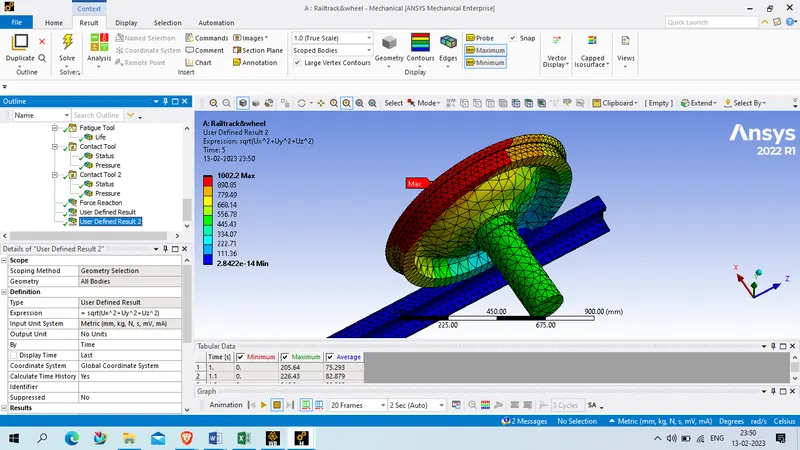
the result of both cases are same.