Week 2 Railwheel and Track
Aim :
To solve the given Railwheel and track using ANSYS software.
Objective :
To analysis the given model and to generate results in the solution part.
In case 1 compare the solution of bearing load 500000N with 100000N.
In case 2 check the user defind result with the total deformation.
Procedure :
Assign the material property in static structural workbench engineering data.
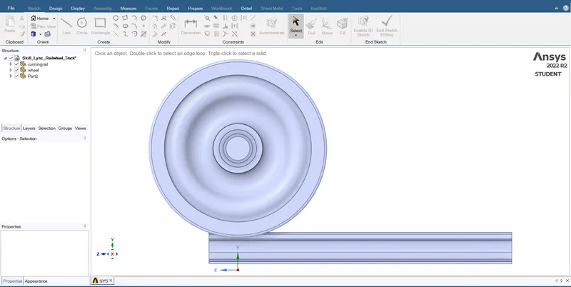
Import the given geometry to the workbench and check the imported geometry using Spaceclaim edits.
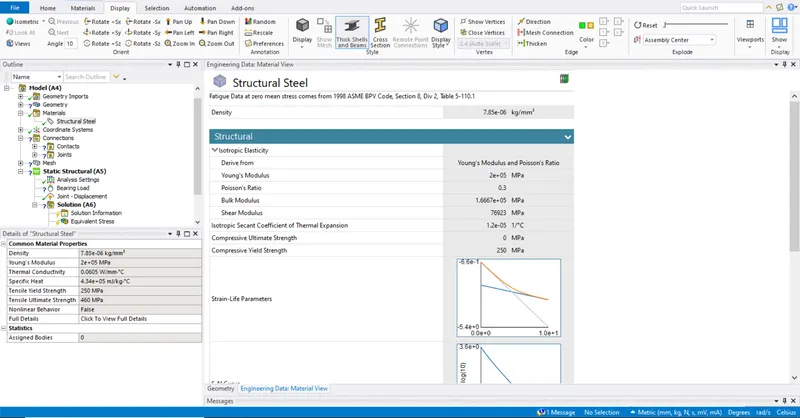
Material property is not given so we choose default material as structural steel.
For model part we work in the mechanical window there we add inputs required for analysis.
In contact tab update the different contact type in the given model.
Types of contact,
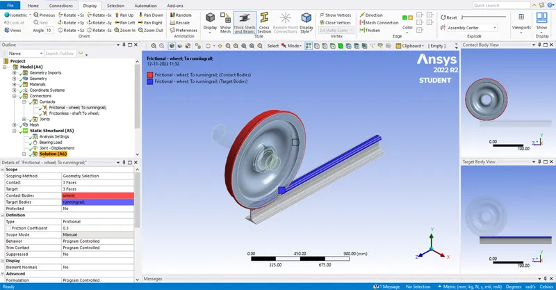
Frictional contact between wheel and track,
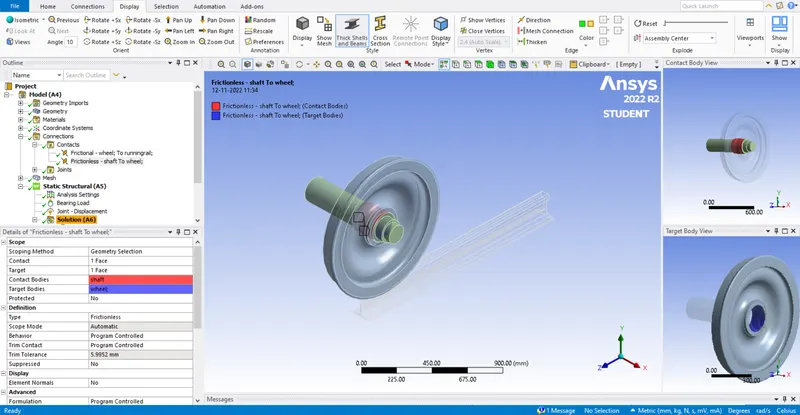
Frictionless between shaft and wheel.
In joint tab update different types of joints in the given model.
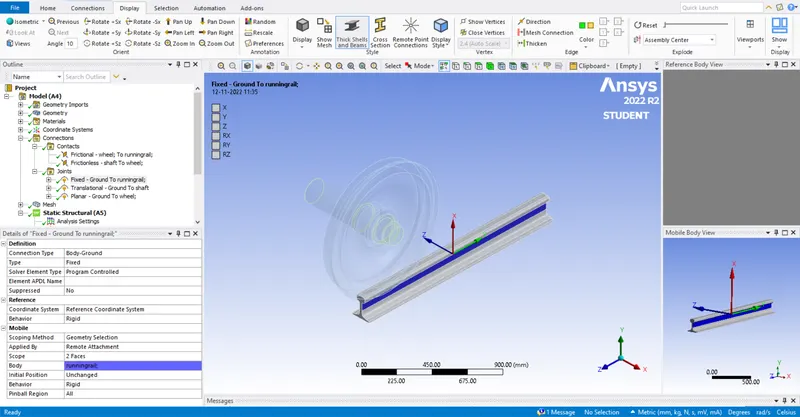
Fixed joint to fix the track ground,
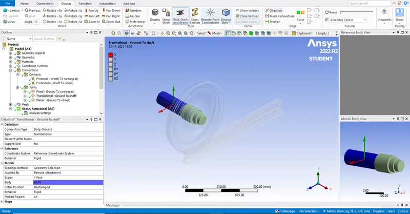
Translational joint to the shaft body ground,
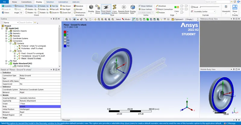
Planar joint to the face of the wheel body ground.
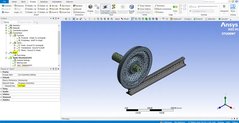
Mesh is generated for a value of 35mm and facing is done on the frictional part for 35mm.
In analysis settings we input the values about number of steps and formula for analysis and output controls.
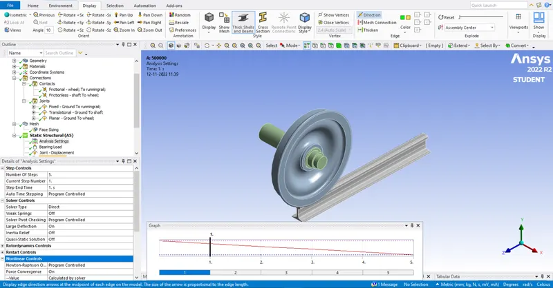
The bearing load is applied in the circular face of the wheel between the shaft and wheel.
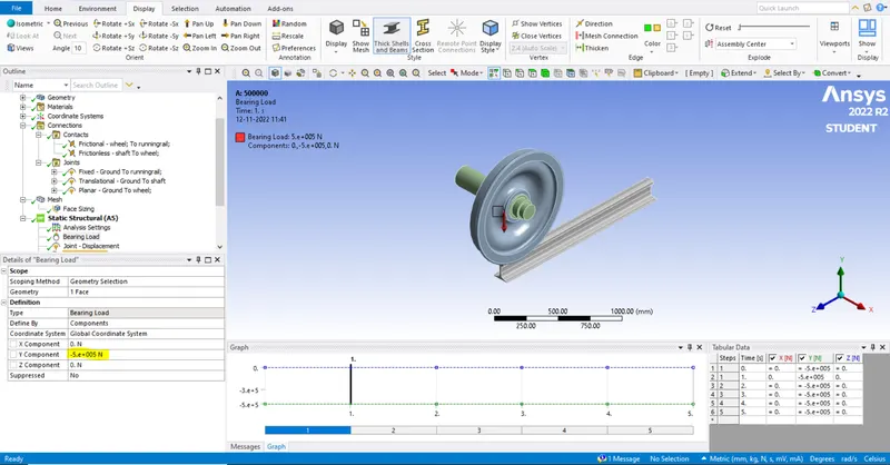
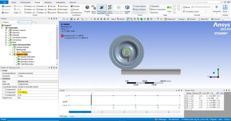
Here we do for two different cases with load values 100000N and 500000N to compare the stress developed.
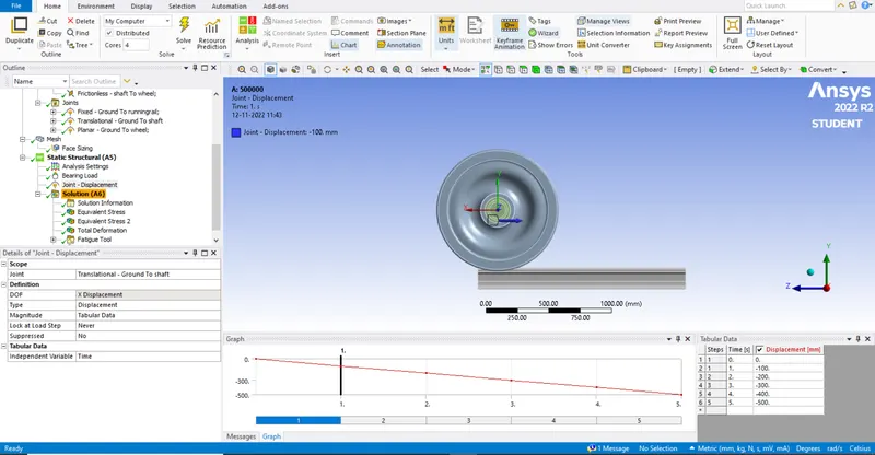
We apply the magnitude table value for displacement joint as per the DOF.
In solution part we choose what solution is asked for this analysis.
They are,
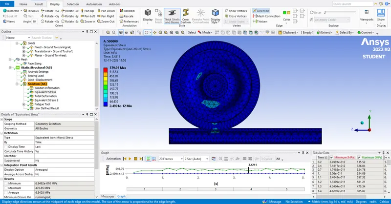
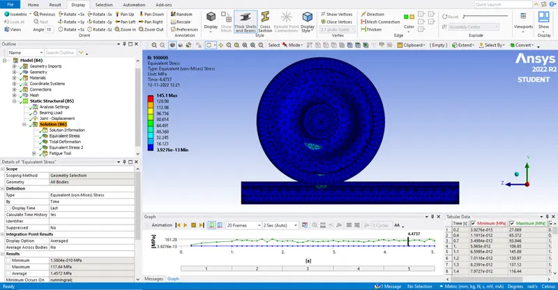
Equivalent stress,
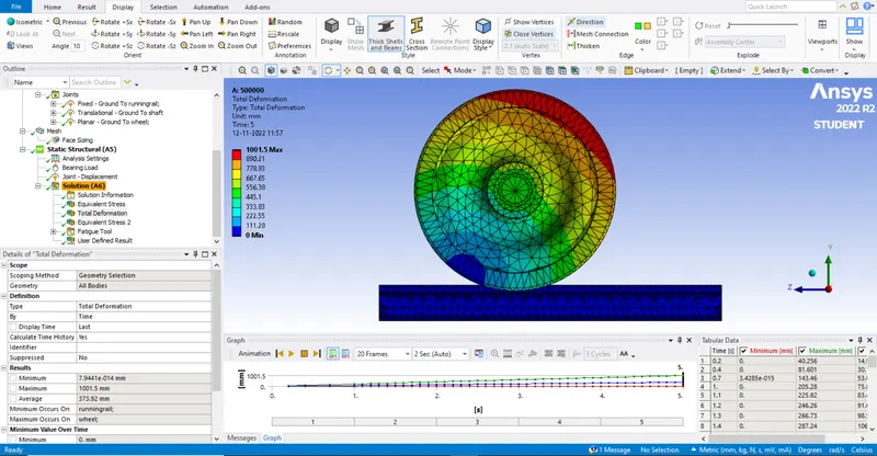
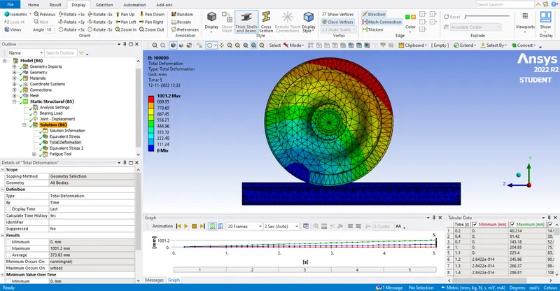
Total deformation,
Fatigue tool,
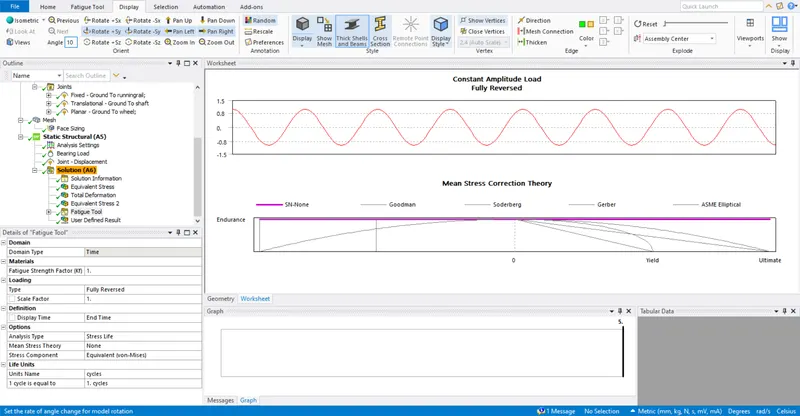
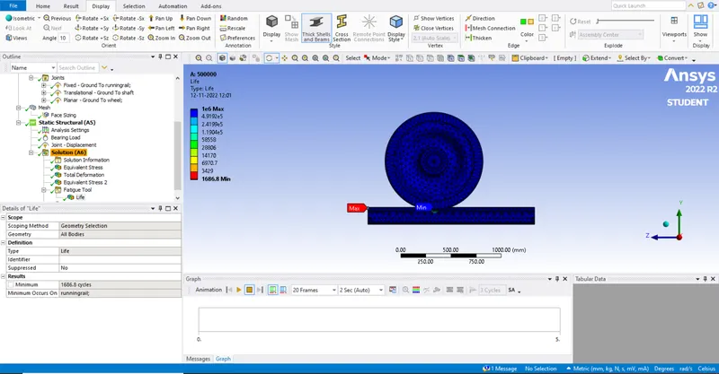
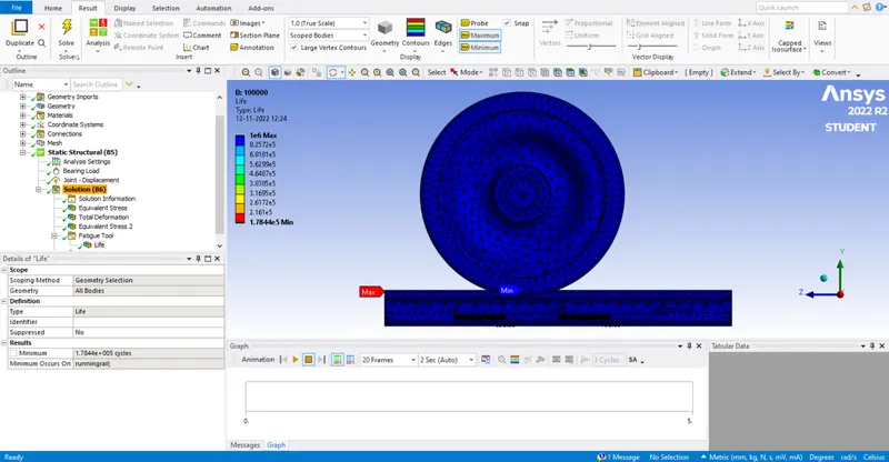
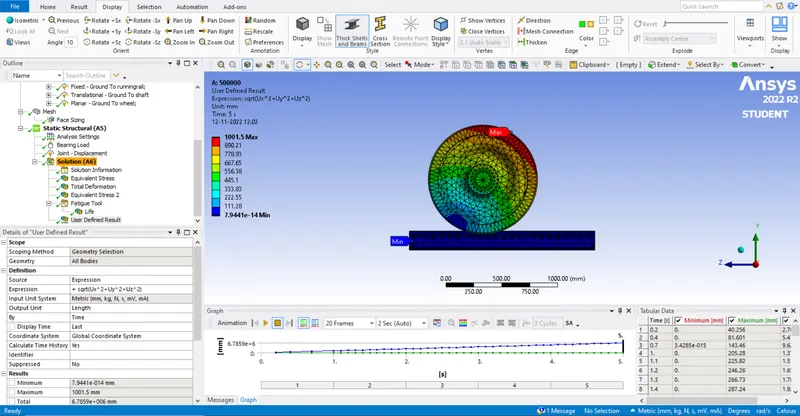
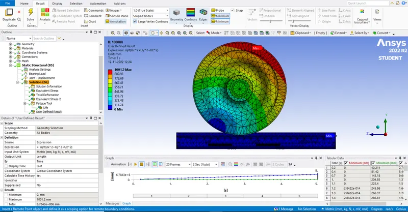
User defined result.
Conclution :
From the above analaysis and solution we compare the values whish is requrid for this model and tabulate the values below.
| Bearinf load/ Solution | Equivalent stress | Total deformation | Life in cycles | User defined result |
| 500000N | 579.95Mpa (max) | 1001.5mm |
1e^6 (max), 1686.8 (min) |
1001.5 (max) |
| 100000N | 145.1Mpa (max) | 1001.2mm |
1e^6 (max), 1.7844e^5 (min) |
1001.2 (max) |
case 1 : The material property is same for both but the stress developed is five times higher when compared due to the higher value of bearing load applied between the wheel and shaft. Due to that we got higher equivelnt stress.
case 2 : The user defined result is found by using the equation sqrt(Ux^2+Uy^2+Uz^2) where the total deformation is the sum of three mutual directional axis so the evaluvated is same.
Result :
We got the requried solution for the given rail wheel model successfully using ANSYS software.