Week 2 Railwheel and Track
AIM:
Simulate the railwheel and track for their lifecycle and the stress, strain and total deformation provided by the wheel running on the track by the given forces.
RAILWHEEL:
A train wheel or rail wheel is a type of wheel specially designed for use on railway tracks. The wheel acts as a rolling component, typically pushed onto an axle and mounted directly on a railway carriege or locomotive.The powered wheels under the locomotive are called driving wheels. Wheels are initially cast or forged and then heat-treated to have a specific hardness. New wheels are machined using a lathe to a standardized shape, called a profile, before being installed onto an axle. All wheel profiles are regularly checked to ensure proper interaction between the wheel and the rail. Incorrectly profiled wheels and worn wheels can increase rolling residance, reduce energy efficiency and may even cause a darrailment.
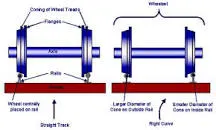
It is a means of transport, on vehicles which run on tracks (rails or railroads). It is one of the most important, commonly used and very cost effective modes of commuting and goods carriage over long, as well as, short distances.A wheelset is a pair of railroad vehicle wheels mounted rigidly on an axle such that both wheels rotate in unison. Wheelsets are often mounted in a bogie a pivoted frame assembly holding at least two wheelsets – at each end of the vehicle.
OBJECTIVES:
Case 1: Multiply the bearing load by 5 times and compare the results with the load of 100000 N (As done in week 2 video). Compare the Total Deformation, Equivalent stress, and the life under both the loads
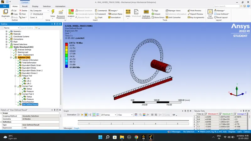
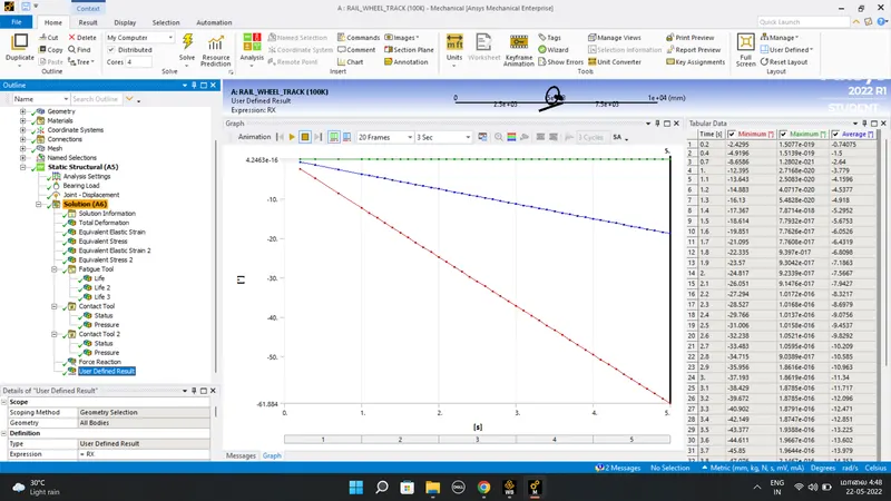
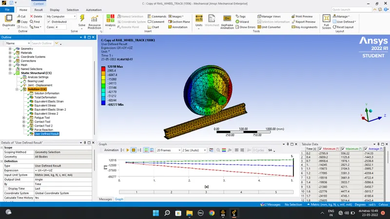
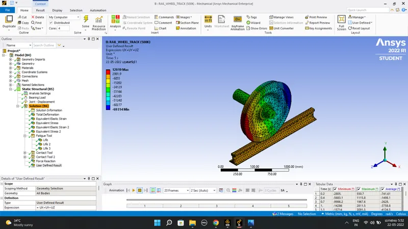
Case 2: Implement a User-defined result and calculate the Total Deformation from this result and check if it is the same as that obtained by the inbuilt result by ANSYS for a load of 100000 N.
PROCEDURE:
- Since the drop the static structal in the ansys workbench.
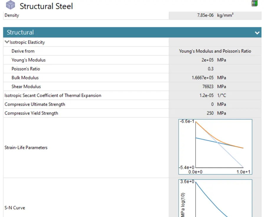
- Next select the suitable material for this simulation, that material is structual steel.
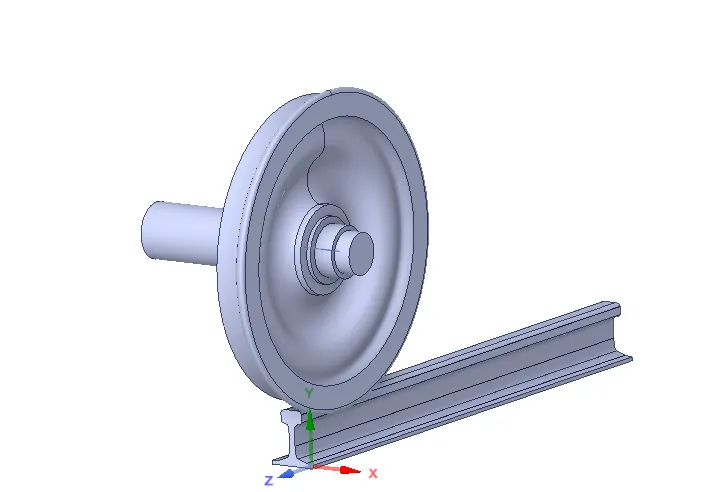
- Then next is import the geometry, then open the mechanial module.
Geometry
Material properties
- After open mechanical module, it's having some steps, thats are material, connection, mesh and staic structural
- First assign the material is the structural steel in the mechanical module.
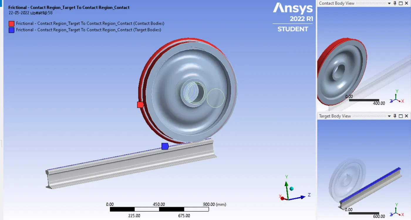
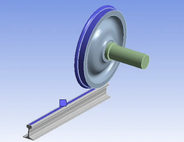
- Open the connection, change the rename then choose the track and wheel assign the type as frictional and frictional coefficient as 0.3. Then choose the wheel and shaft is assign the frictionalless.
connections
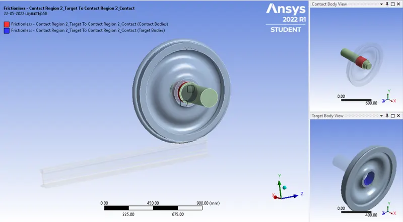
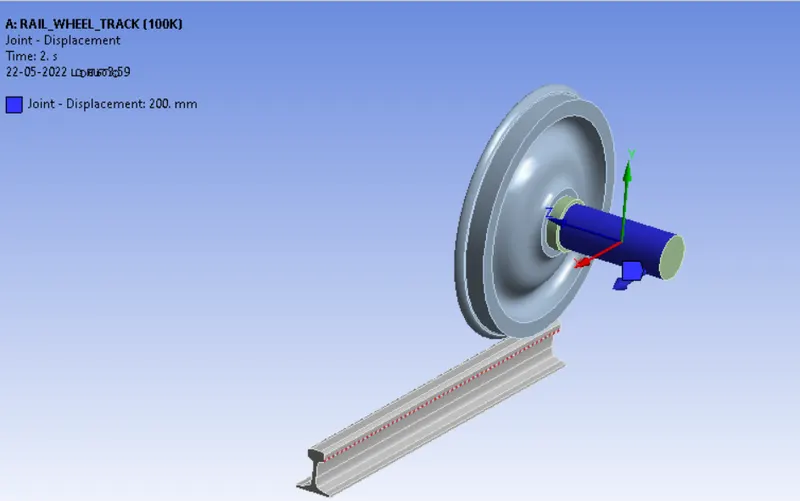
- After finished connection, for giving the parameters, the joints to be the applied for the to be run on the simulation while evaluating the result.
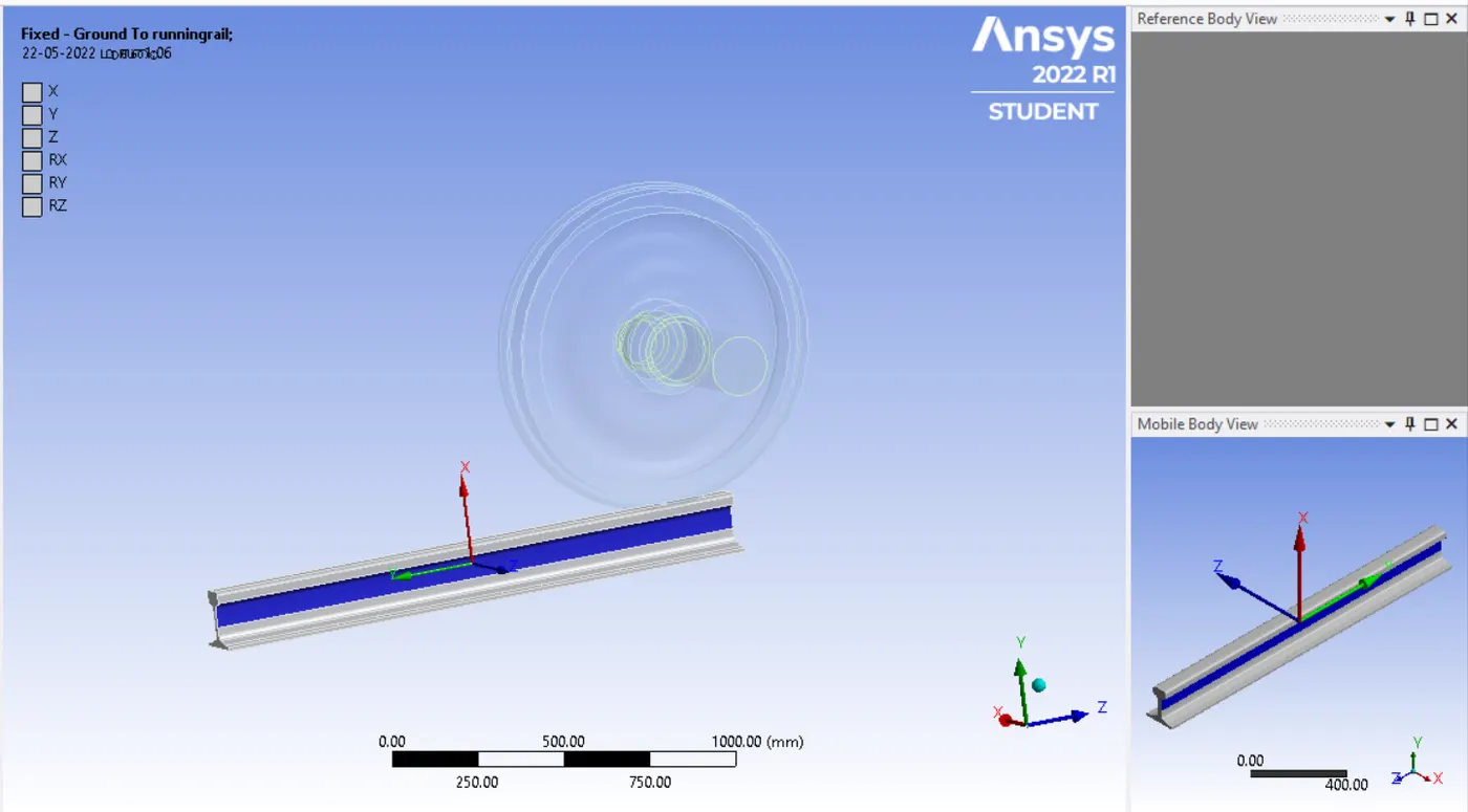
Fixed joint : This joint for the ground to runningrail, select the both side of the track, the fixed joint connection type is bodt to ground
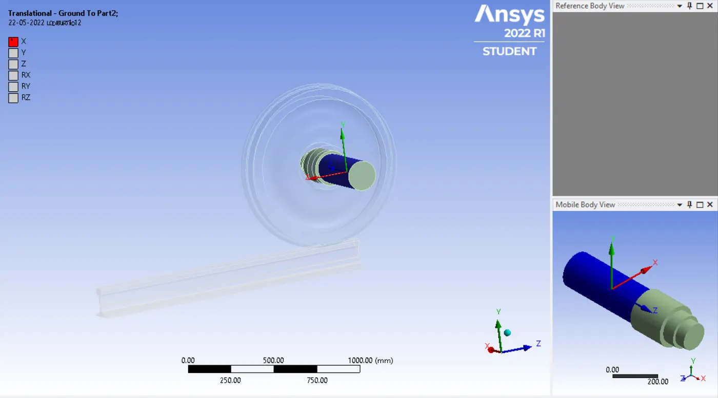
Translational joint : This joint assign for shaft
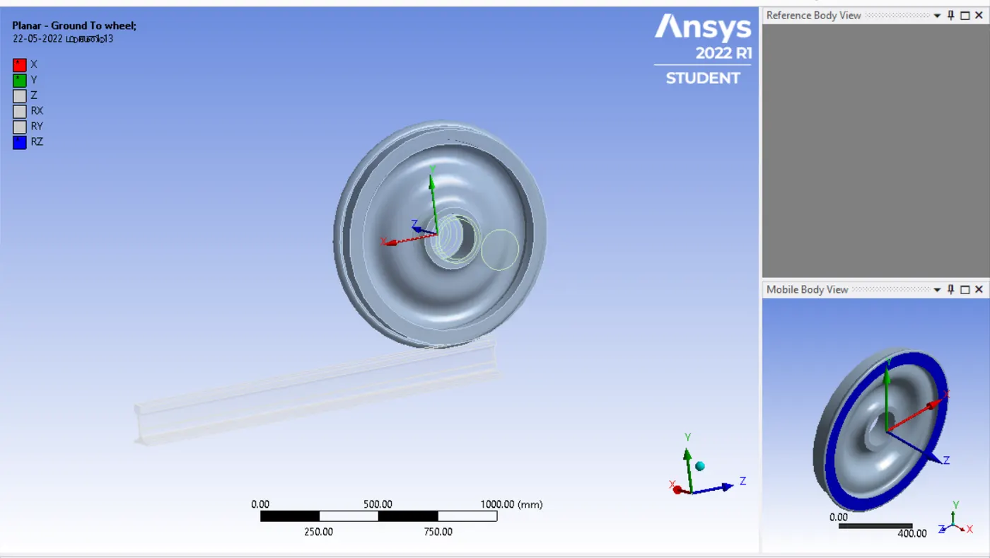
Planar joints : Planar joint for the wheel , the plannar joint as connection joint is body to ground.
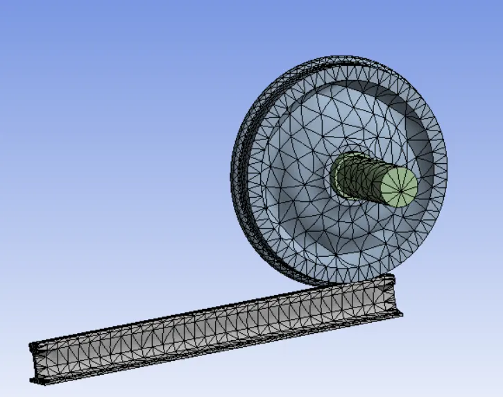
- Mesh, the mesh size for the wheel and track is 50mm, the nodes and elements are 12947 & 6519
- Then insert the mesh facing, the facing size is 35mm, select the faces of wheel move along the track,
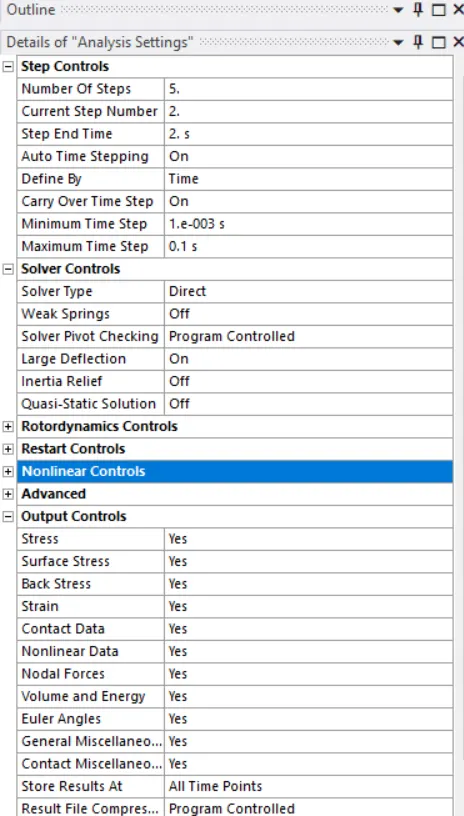
- The next step is analysis setting giving the appropriate parameters in the analysis setting with some joint load that need to apply on the geometry.
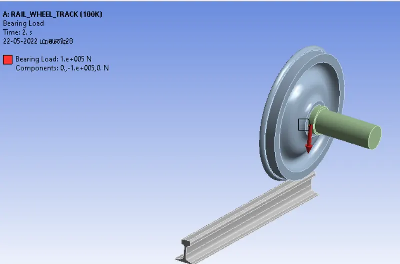
- After getting the parameters of the analysis setting two loads are the applied
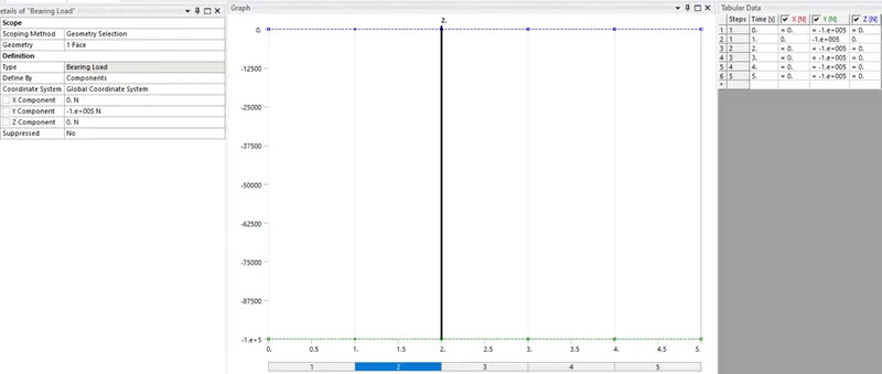
Bearing load
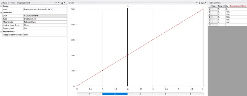
Joint Displacement load
- The bearing load applied for in between the wheel and shaft, applied load for 100000N
- Joint Displacement load
The following parameters need to be evaluated for the results of the rail wheel and track
- Total deformation
- Equivalent stress
- Life cycle
- User defind result
RESULT:
Case 1:
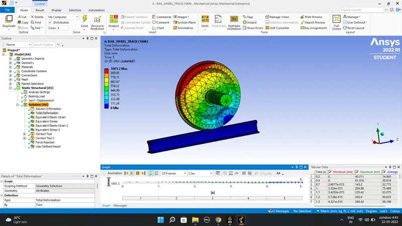
Resut for 100k
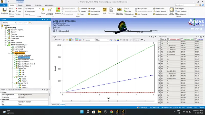
Total Deformation and graph
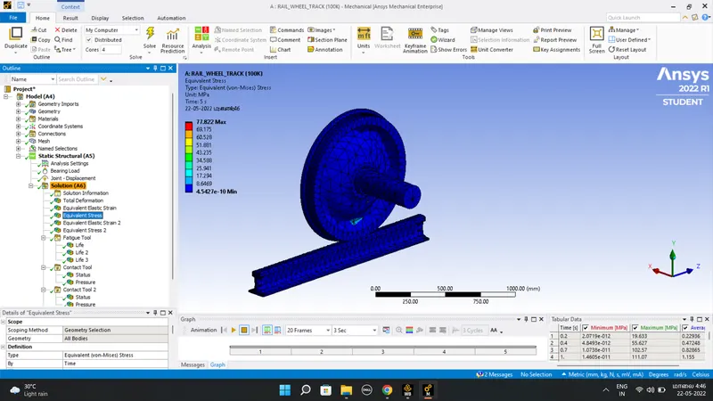
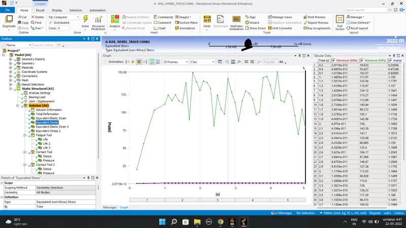
Equivalent stress
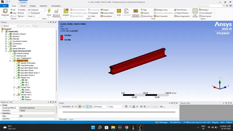
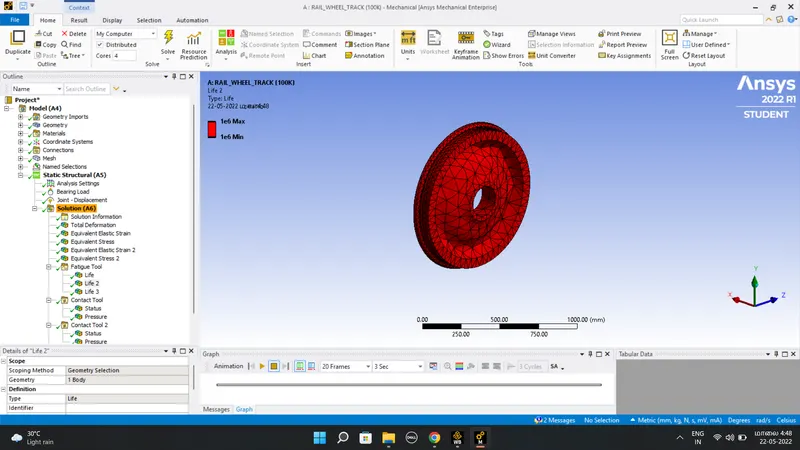
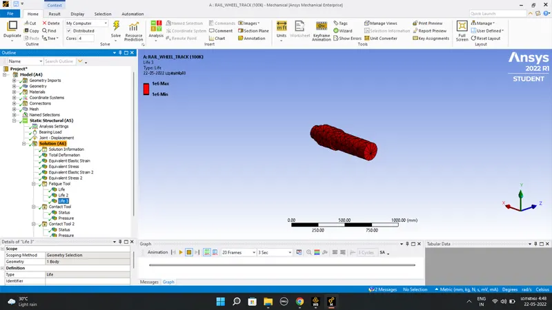
Life
User defind result
Resut for 500k
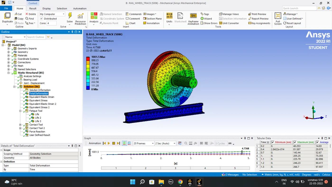
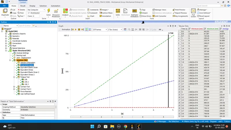
Total Deformation
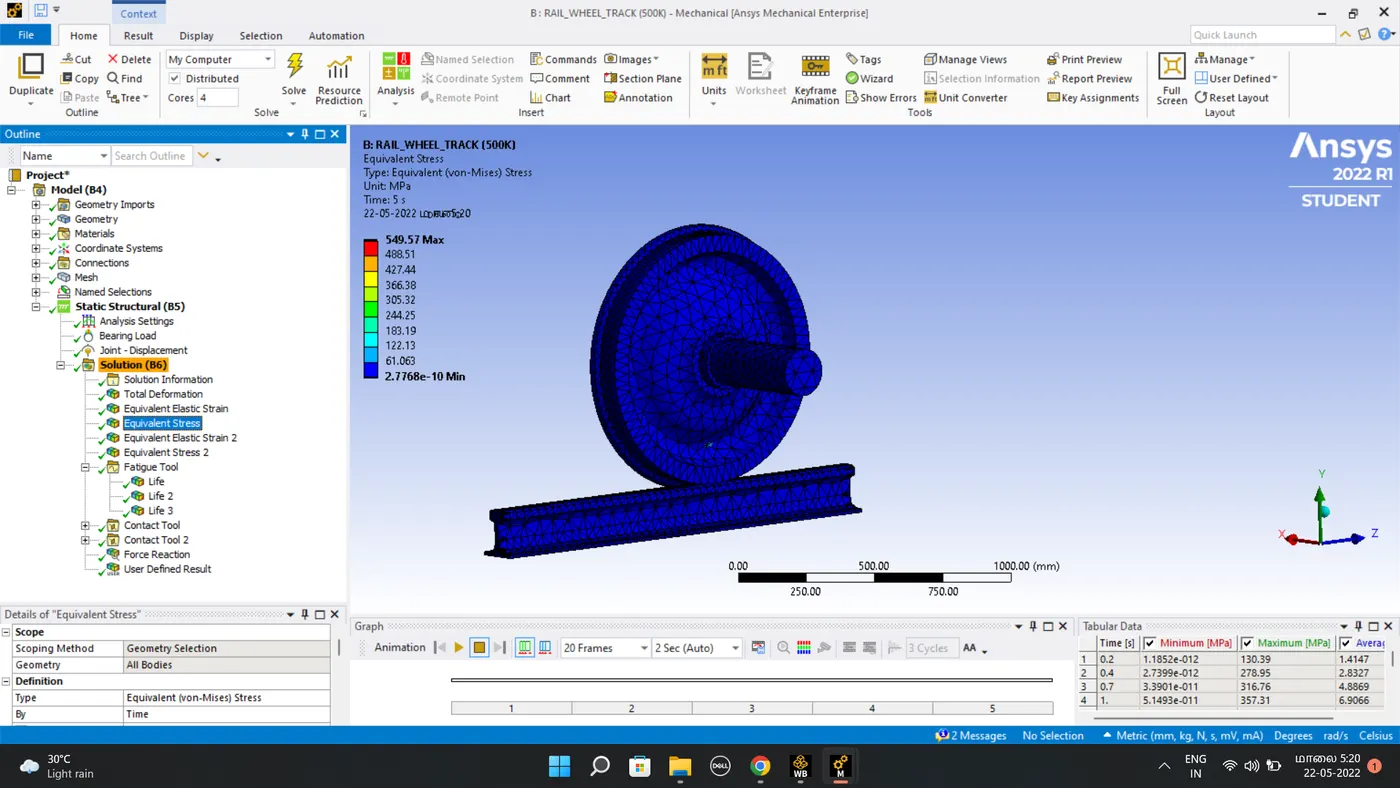
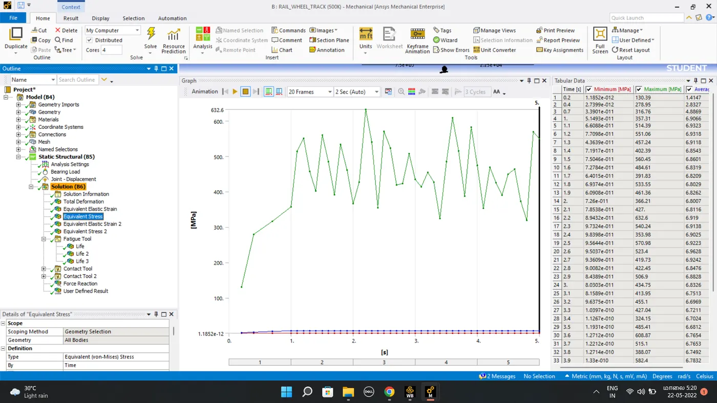
Equivalent stress
Life
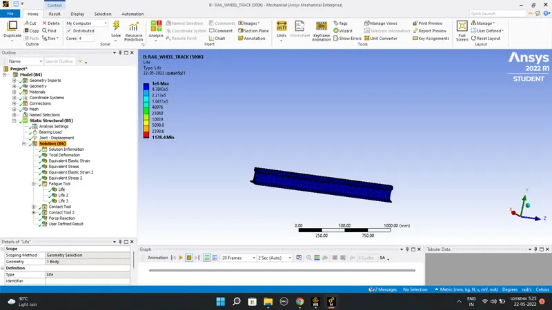

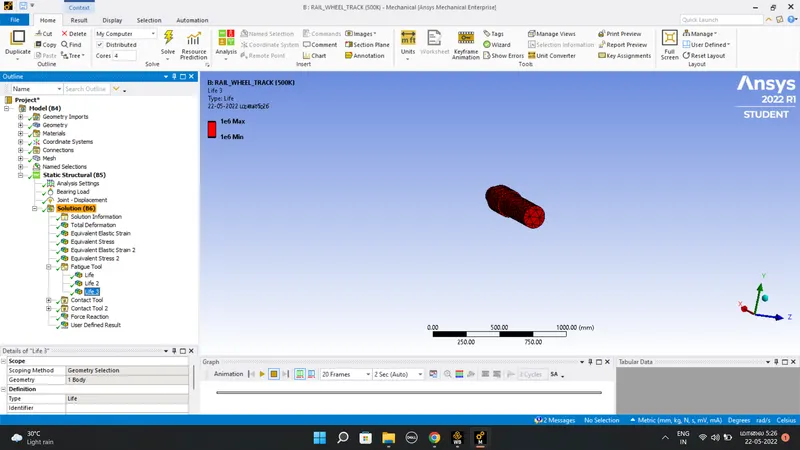
CONCLUSION:
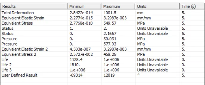
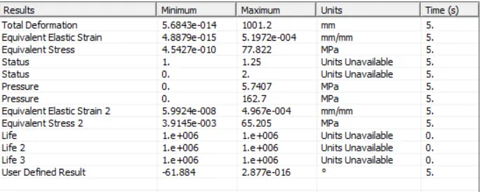
The above fig is result of the load 100k and load 500k, the result shows that the load increases, as the force on the trackwheel simulation the equivalent stress and deformation increases, the force is directly proportional to the stress value. And the life cycle loads 1e^6 max.
CASE 2 : USER DEFINED RESULT
The evaluate the user definned results for both loads as i have taken the result for both loads. The expression used to evaluate the result expression used is UX+UY+UZ and the output unit is displacement.
load 100k
load 500k
simulation file link
https://drive.google.com/file/d/1yi-Ik-nBgey7dNKlYug7YSE1698RbTPv/view?usp=sharing