Week 2 Railwheel and Track
Railwheel and Track
Aim
To setup a given railwheel and track model to check for deformation,strain and life under 2 different loads
Theory
A train wheel or rail wheel is a type of wheel specially designed for use on railway tracks. The wheel acts as a rolling component, typically pushed onto an axle and mounted directly on a railway carriage (also called bogie). Wheels are initially cast or forged and then heat-treated to have a specific hardness. New wheels are machined using a lathe to a standardized shape, called a profile, before being installed onto an axle. All wheel profiles are regularly checked to ensure proper interaction between the wheel and the rail. Incorrectly profiled wheels and worn wheels can increase rolling resistance, reduce energy efficiency and may even cause a derailment.
Almost all train wheels have a curved projection, a flange, on one side to keep the wheels, and hence the train, running on the rails when the limits or tests of alignment are reached: when a bend is taken at appropriate speed, when there are strong sidebreezes, and to withstand e.g. most common emergent defects in trackbed, rail and mild debris.
Procedure
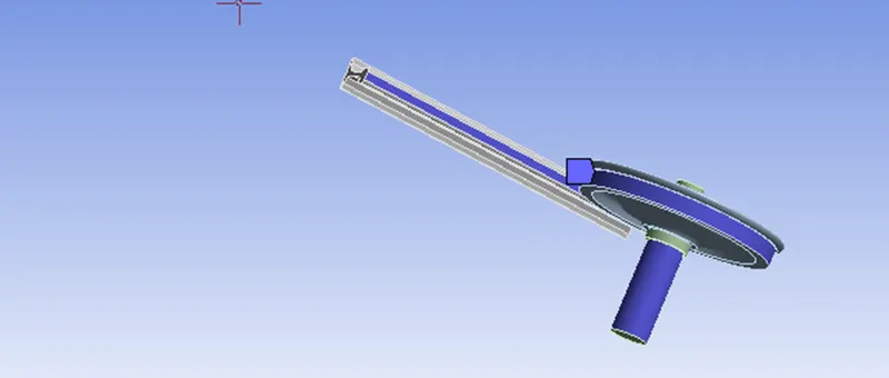
- Start a new static structural model in ansys and import the model
- Open Ansys mechanical by double clicking the icon
- Check that the materials (structural steel) were properly assigned to the model
- Verify proper contact regions
Frictionless-Shaft and wheel
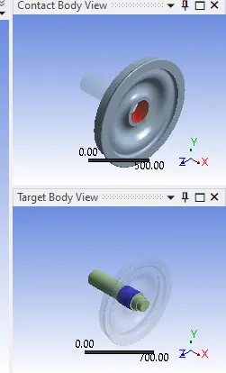
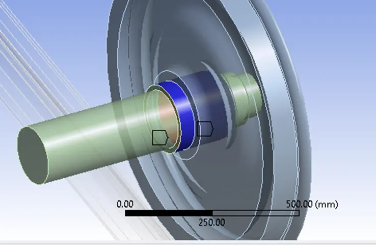
Frictional-Wheel and rail
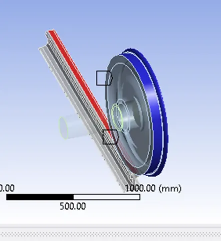
For the connection between the wheel and the rail, we will be defining a friction coefficient of 0.3.
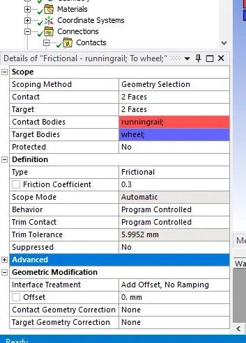
- For this setup, we will need to create 3 different joints
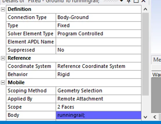
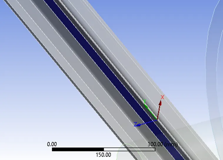
Fixed Body-Ground Joint
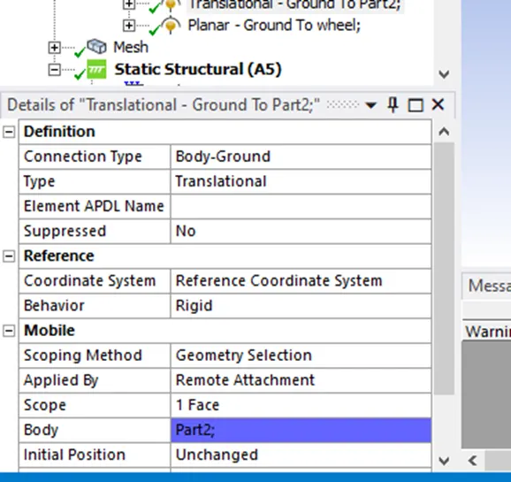
Translational-Body -Ground
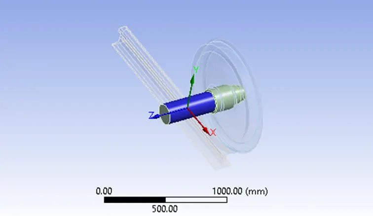
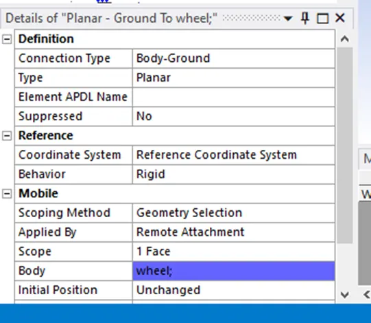
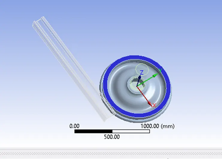
Planar-Ground to wheel
Meshing
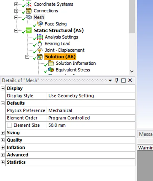
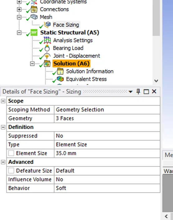
Set a default mesh size of 50mm but create a face sizing for the areas of interest with a mesh size of 35mm
The areas of interest are the shaft ,wheel and rail faces that are in contact with each other during the simulation.
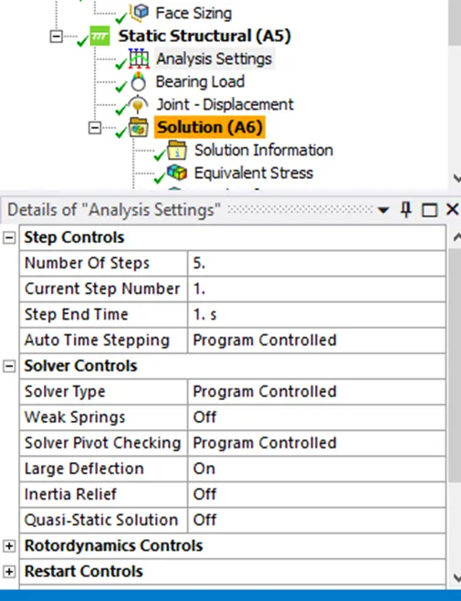
Analysis Settings
For the first step,we keep auto timestepping as program controlled and switch on large deflection.
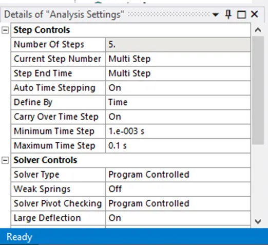
For the other steps, you switch on auto timestep and set it as follows.
Also set everything in output controls to yes for all timesteps
Loading
Set the load for the iniital case as 100000N and make sure the displacement is along the proper side, if it goes off the rail change the reference axis.
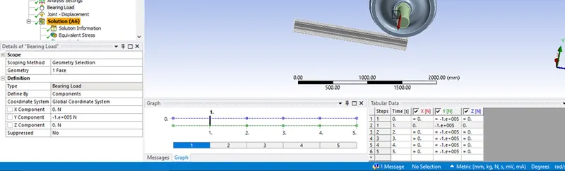
(you can also just change the axis instead of setting to negative load)
For case 2, simply change the load to 500000N and rerun the simulation
The displacement in both cases is defined for a total of 500mm, increasing gradually by 100mm per second.
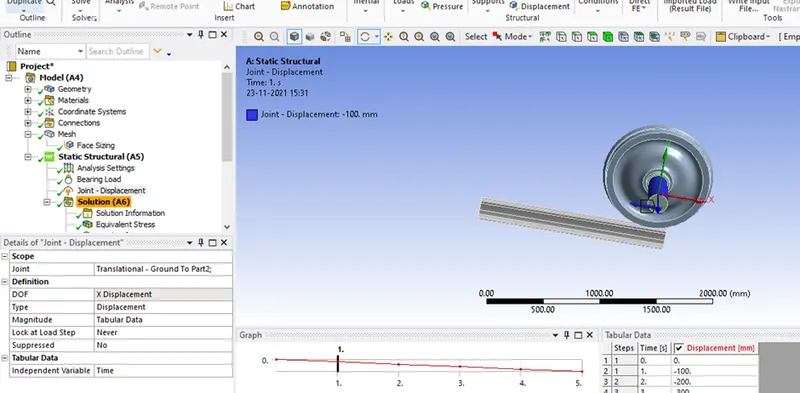
Set your output blocks as follows.
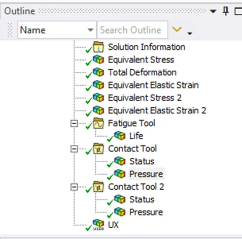
For UX, the equation to be followed is sqrt(Ux^2+UY^2+UZ^2).
Post Processing
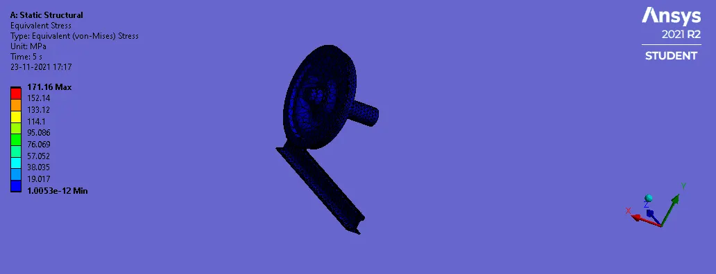
Case 1 : Load of 100000N
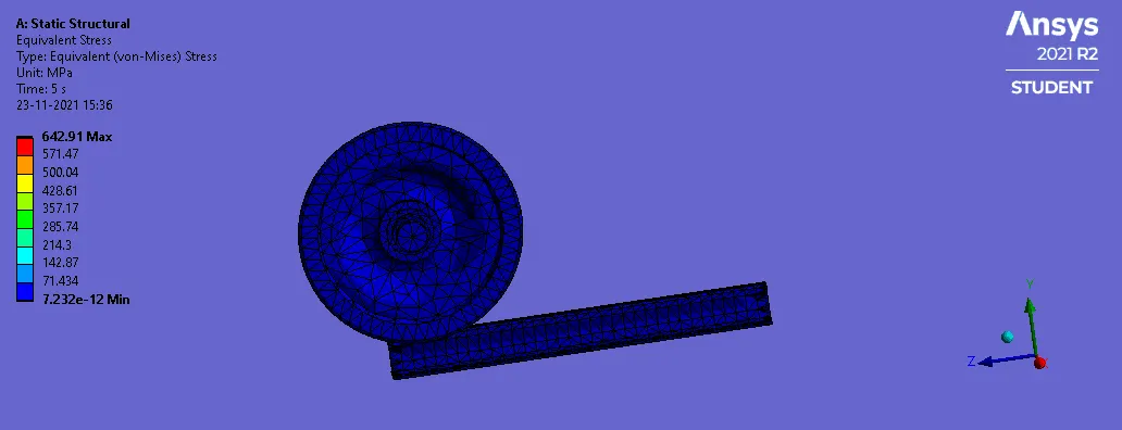
Case 2: Load of 500000N
Tabulated Results of Case1 and Case 2
|
Load on Bearing (N) |
100000 |
500000 |
|
Maximum Stress (MPa) |
171.16 |
642.91 |
|
Maximum Strain |
0.00014 |
0.0045 |
|
Fatigue Life (cycles) |
3.5421 e^5 |
1891.9 |
|
Maximum Stress on Wheel (MPa) |
169.06 |
580.94 |
|
Maximum Strain on Wheel |
0.00014 |
0.0045 |
|
Maximum Pressure on Wheel-Rail (MPa) |
212.43 |
936.45 |
|
Maximum Pressure on Shaft-wheel (MPa) |
10.69 |
37.163 |
|
Deformation (mm) |
1001.4 |
1001.4 |
|
User defined displacement (mm) |
1001.4 |
1001.4 |
It can be seen that that the total displacement is the same in both cases with a maximum displacement of 1001.4mm.This is also the case with the user defined result giving the same values.
The fatigue life of the bearing significantly decreases by a massive amount (from 3.54 e^5 cycles to 1891.9) due to the significant increase in bearing load (From 100000N to 500000N).
Conclusion
The behaviour of a rail and wheel system was observed in two different loading cases of 100000N and 500000N and the stresses, strains, deformation andfatigue life cycles experienced were noted.
It was seen that the user defined displacement and total deformation were identical in both cases and that the significant increase in load greatly reduced the lifetime of the system by a huge margin.