Week 2 - Flow over a Cylinder.
AIM:
To Simulate the flow over a cylinder and explain the phenomenon of Karman vortex street.
OBJECTIVES:
1. Calculate the drag and lift coefficient over a cylinder by setting the Reynolds number to 10,100,1000,10000 & 100000. (Run with steady solver)
2. Simulate the flow with the steady and unsteady case and calculate the Strouhal Number for Re= 100.
INTRODUCTION:
VORTEX SHEDDING:
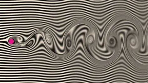
In fluid dynamics, vortex shedding is an oscillating flow that takes place when a fluid such as air or water flows past a bluff (as opposed to a streamlined) body at certain velocities, depending on the size and shape of the body. In this flow, vortices are created at the back of the body and detach periodically from either side of the body forming a Kármán vortex street. The fluid flow past the object creates alternating low-pressure vortices on the downstream side of the object. The object will tend to move toward the low-pressure zone.
REYNOLDS NUMBER:
The Reynolds number is the ratio of inertial forces to viscous forces within a fluid that is subjected to relative internal movement due to different fluid velocities. A region where these forces change behavior is known as a boundary layer, such as the bounding surface in the interior of a pipe. A similar effect is created by the introduction of a stream of high-velocity fluid into a low-velocity fluid, such as the hot gases emitted from a flame in air. This relative movement generates fluid friction, which is a factor in developing turbulent flow. Counteracting this effect is the viscosity of the fluid, which tends to inhibit turbulence. The Reynolds number quantifies the relative importance of these two types of forces for given flow conditions, and is a guide to when turbulent flow will occur in a particular situation.[6]
This ability to predict the onset of turbulent flow is an important design tool for equipment such as piping systems or aircraft wings, but the Reynolds number is also used in scaling of fluid dynamics problems and is used to determine dynamic similitude between two different cases of fluid flow, such as between a model aircraft, and its full-size version. Such scaling is not linear and the application of Reynolds numbers to both situations allows scaling factors to be developed.
With respect to laminar and turbulent flow regimes:
- laminar flow occurs at low Reynolds numbers, where viscous forces are dominant, and is characterized by smooth, constant fluid motion;
- turbulent flow occurs at high Reynolds numbers and is dominated by inertial forces, which tend to produce chaotic eddies, vortices and other flow instabilities.[7]
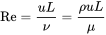
The Reynolds number is defined as[3]
- Re=���=����
where:
- ρ is the density of the fluid (SI units: kg/m3)
- u is the flow speed (m/s)
- L is a characteristic linear dimension (m) (see the below sections of this article for examples)
- μ is the dynamic viscosity of the fluid (Pa·s or N·s/m2 or kg/(m·s))
- ν is the kinematic viscosity of the fluid (m2/s).
STROUHAL NUMBER:
In dimensional analysis, the Strouhal number (St, or sometimes Sr to avoid the conflict with the Stanton number) is a dimensionless number describing oscillating flow mechanisms. The parameter is named after Vincenc Strouhal, a Czech physicist who experimented in 1878 with wires experiencing vortex shedding and singing in the wind.[1][2] The Strouhal number is an integral part of the fundamentals of fluid mechanics.
The Strouhal number is often given as
- St=���,

where f is the frequency of vortex shedding, L is the characteristic length (for example, hydraulic diameter or the airfoil thickness) and U is the flow velocity. In certain cases, like heaving (plunging) flight, this characteristic length is the amplitude of oscillation. This selection of characteristic length can be used to present a distinction between Strouhal number and reduced frequency:
- St=����,

where k is the reduced frequency, and A is amplitude of the heaving oscillation.
PROCEDURE:
Geometry:
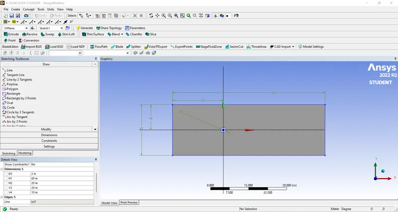
A plate with the dimension of 20*60m is created using a Design modeler.
Meshing:
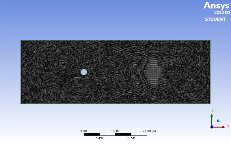
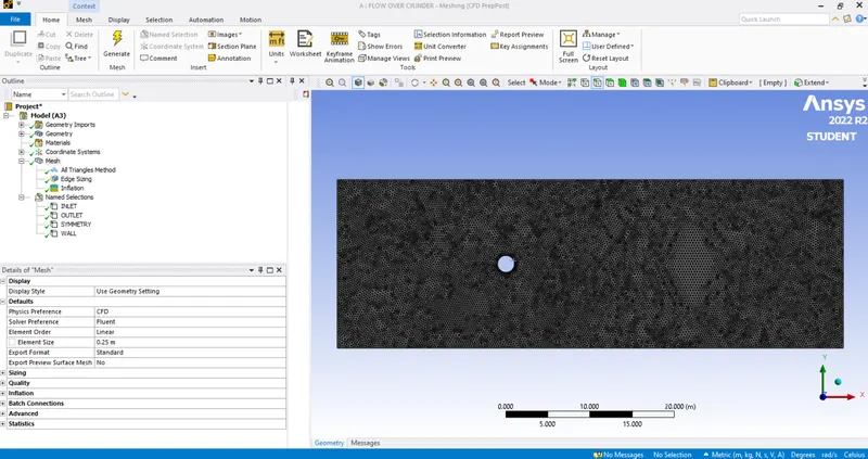
1. select the edges of geometry and named them inlet,outlet,wall, and symmetry.
2. Now select the body and go to mesh and click on generate a mesh with mesh size 0.25 m.To ensure triangular mesh, go to mesh / insert/select triangular mesh type.
NAMED SELECTION:
SIZING:
After generating the mesh, it is seen that size of the circle looks distorted.
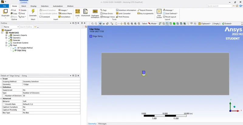
go to mesh/sizing/select circular edge/definition>type > no, of divisions >36.
INFLATION:
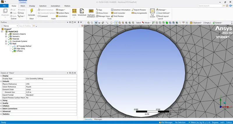
To capture better results near the cylinder wall, go to mesh/inflation / select the body and edge/inflation option : 1st layer thickness /1st layer height:5e-3 m /maximum layer:6.
SOLVING:
1. select laminar flow inside the viscous model.
2. As we wanted to cucustomizematerial property for simulation, go to materials > fluent database > select the material (air) > copy it> rename the name of the material.
BOUNDARY CONDITION:
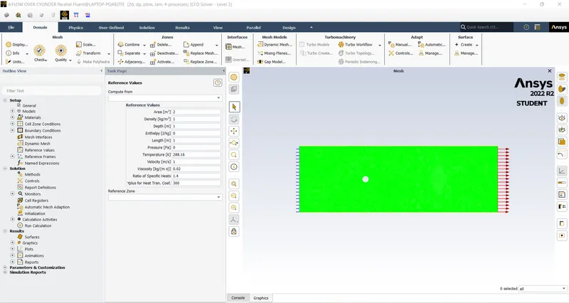
Outlet: gauge pressure = 0 Pa.
wall: no-slip condition.
STEADY-STATE SIMULATION:
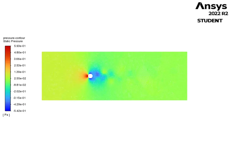
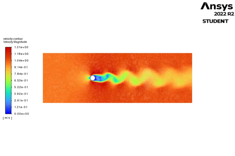
1.Reynolds number = 10.
velocity = 1 m/s.
density = 1 kg/m3.
viscosity = 0.02 Pa-s.
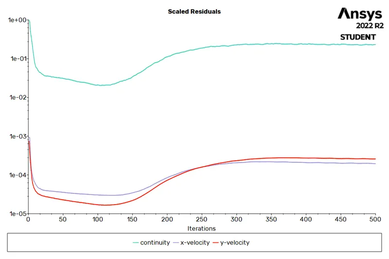
RESIDUAL PLOT:
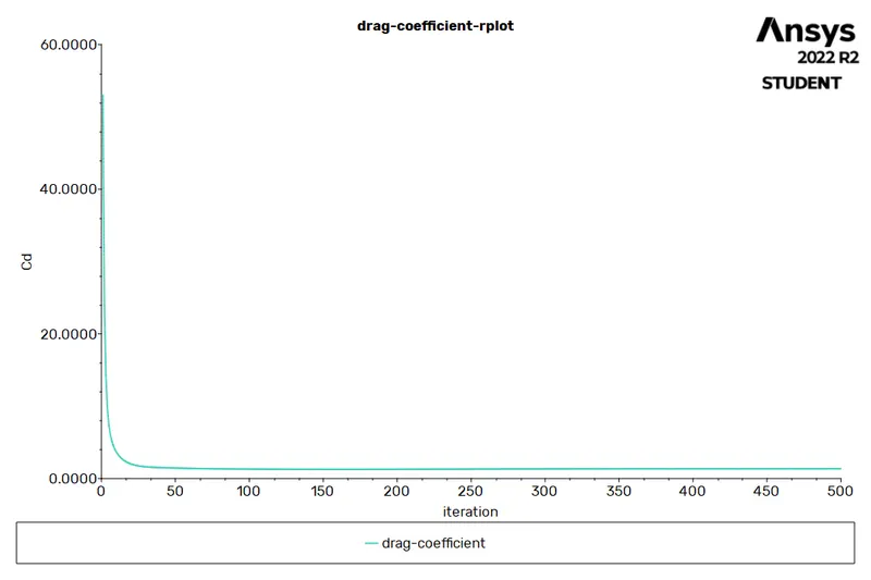
CO-EFFICIENT OF DRAG:
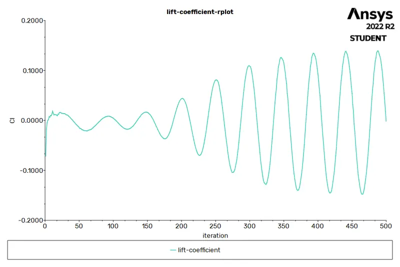
LIFT-COFFICIENT:
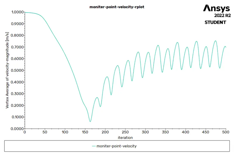
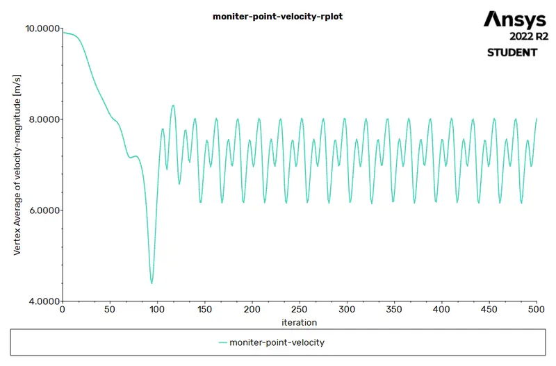
MONITOR POINT VELOCITY:
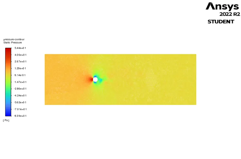
PRESSURE CONTOUR:
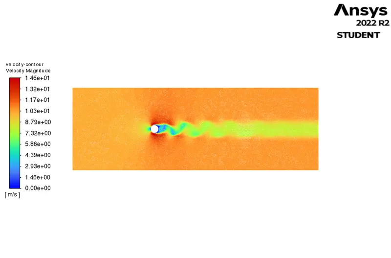
VELOCITY CONTOUR:
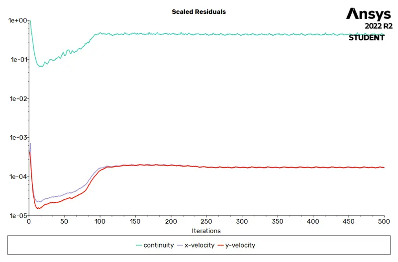
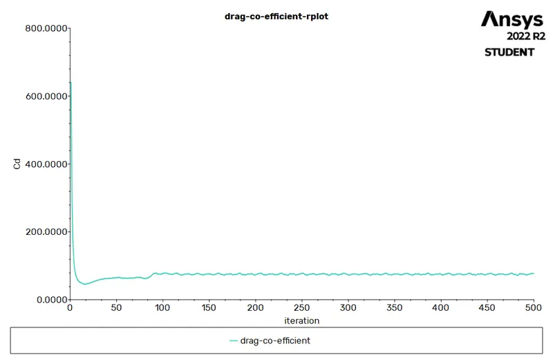
2.Reynolds number = 100.
velocity = 10 m/s.
density = 1 kg/m3.
viscosity = 0.02 Pa-s.
RESIDUAL PLOT:
CO-EFFICIENT OF DRAG:
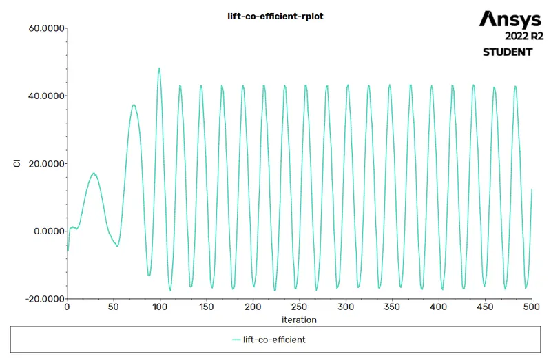
LIFT-COFFICIENT:
MONITOR POINT VELOCITY:
PRESSURE CONTOUR:
VELOCITY CONTOUR:
3.Reynolds number = 1000.
velocity = 100 m/s.
density = 1 kg/m3.
viscosity = 0.02 Pa-s.
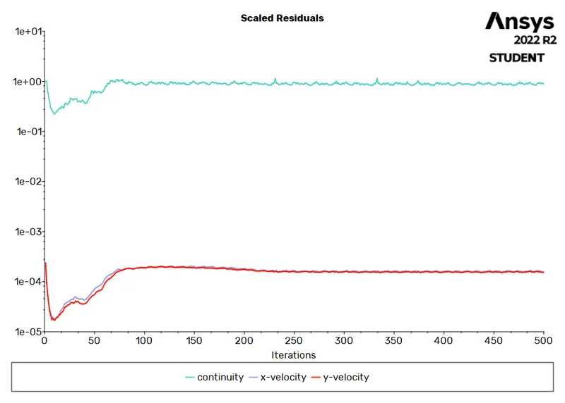
RESIDUAL PLOT:
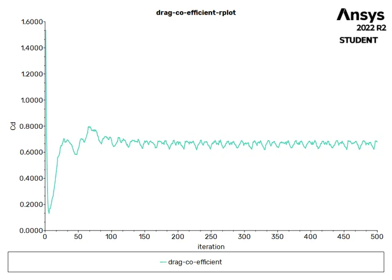
CO-EFFICIENT OF DRAG:
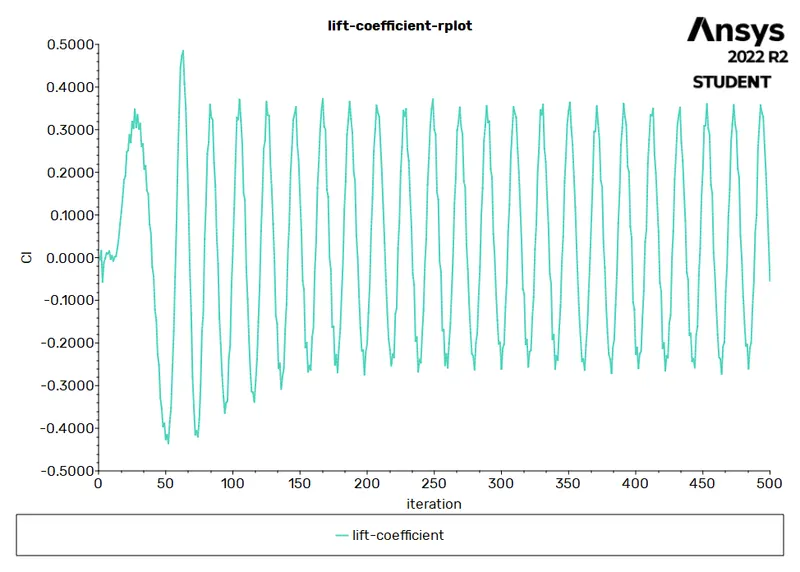
LIFT-COFFICIENT:
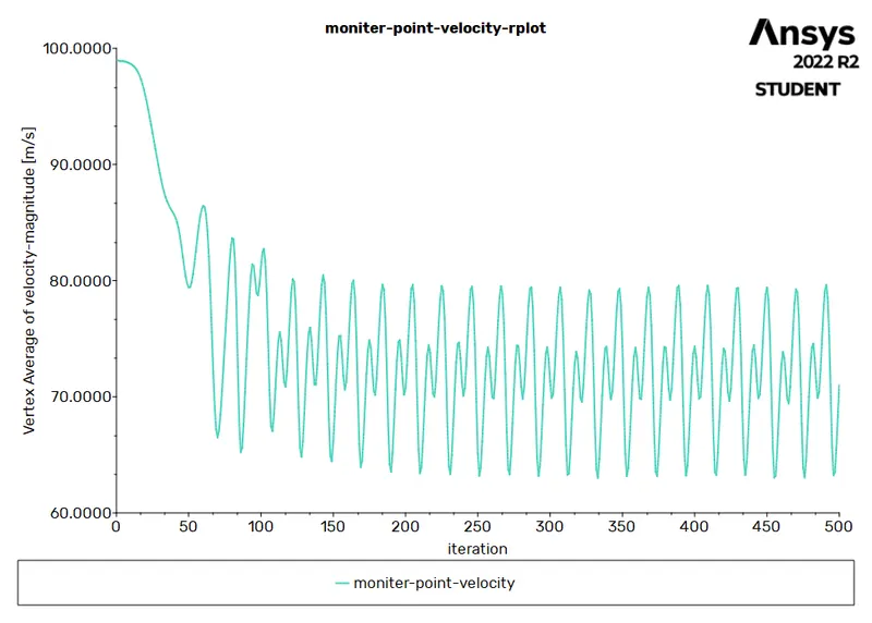
MONITOR POINT VELOCITY:
PRESSURE CONTOUR:
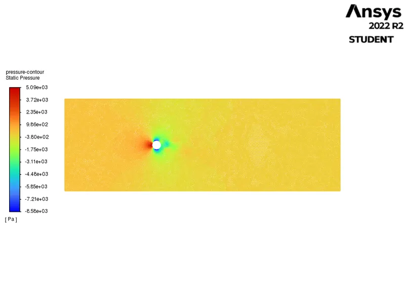
VELOCITY CONTOUR:
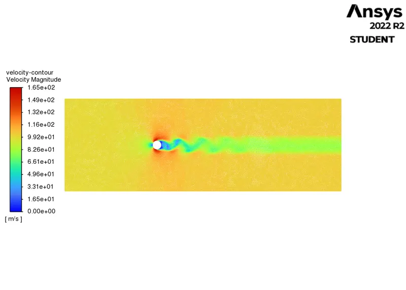
4.Reynolds number = 10000.
velocity = 1000 m/s.
density = 1 kg/m3.
viscosity = 0.02 Pa-s.
RESIDUAL PLOT:
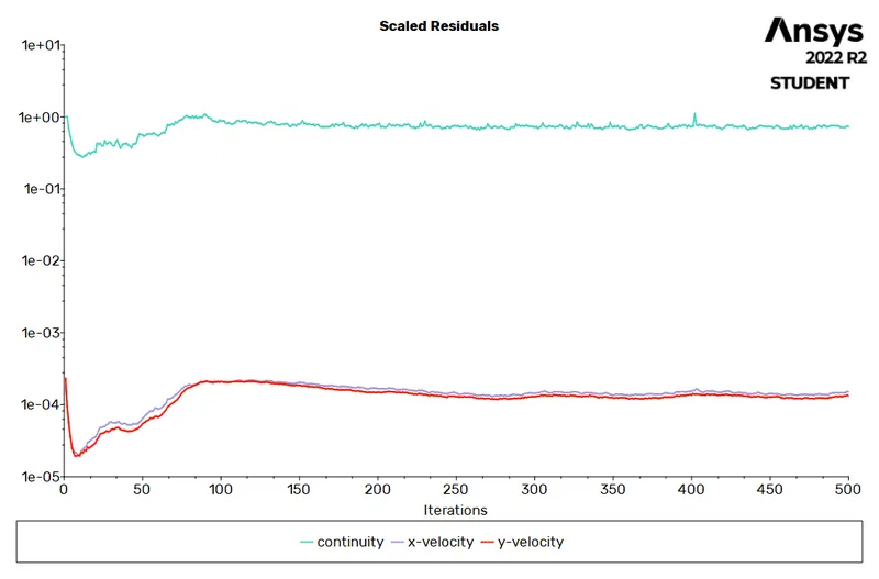
CO-EFFICIENT OF DRAG:
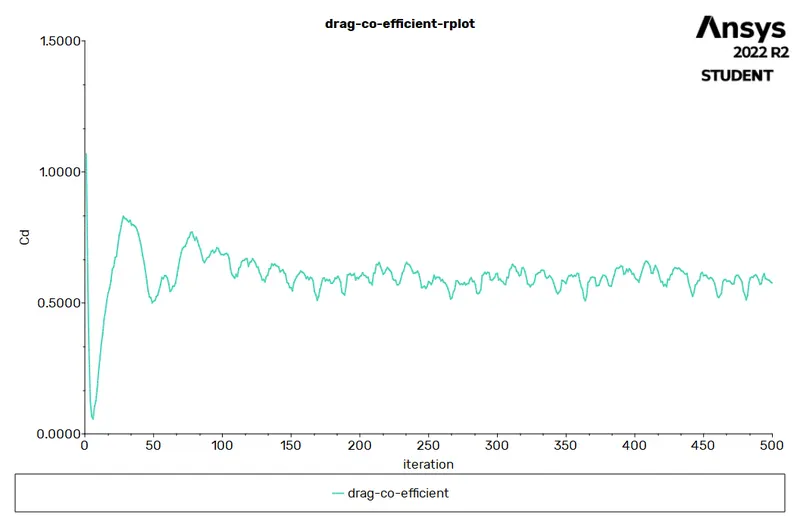
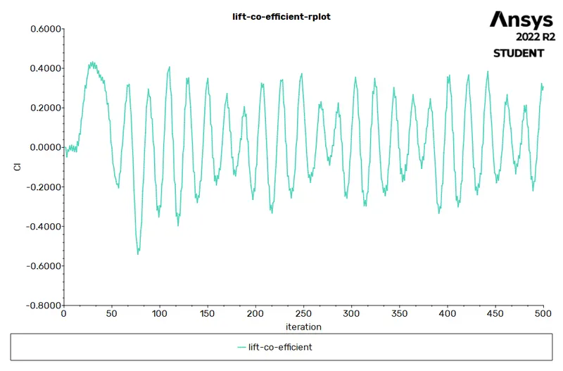
LIFT-COFFICIENT:
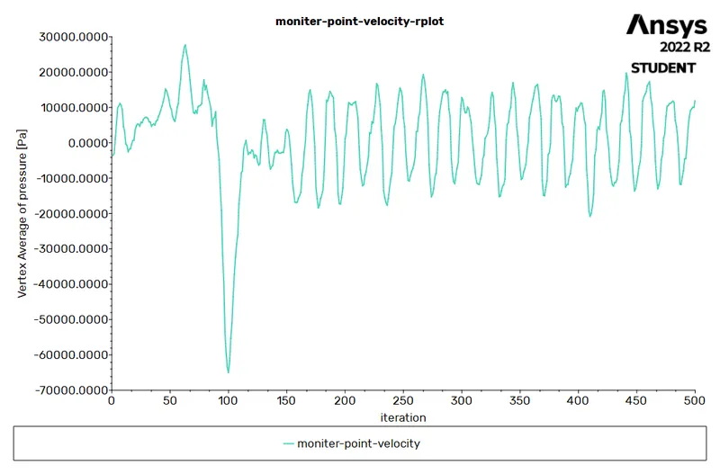
MONITOR POINT VELOCITY:
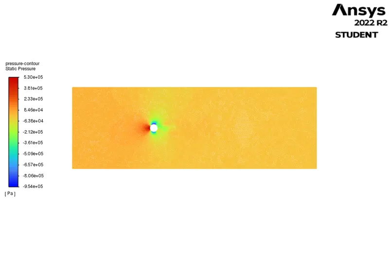
PRESSURE CONTOUR:
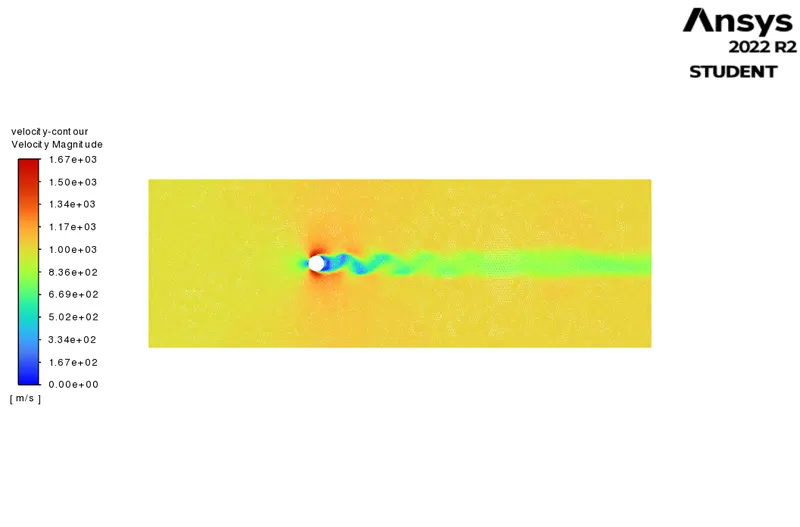
VELOCITY CONTOUR:
5.Reynolds number = 100000.
velocity = 10000 m/s.
density = 1 kg/m3.
viscosity = 0.02 Pa-s.
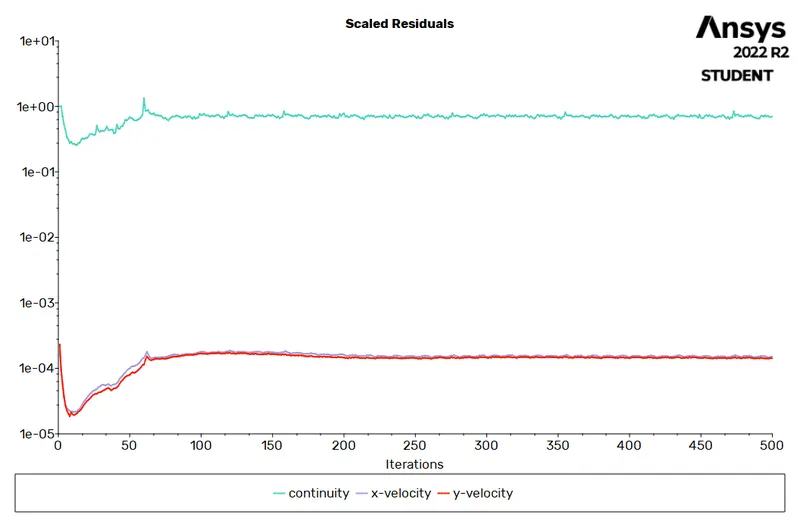
RESIDUAL PLOT:
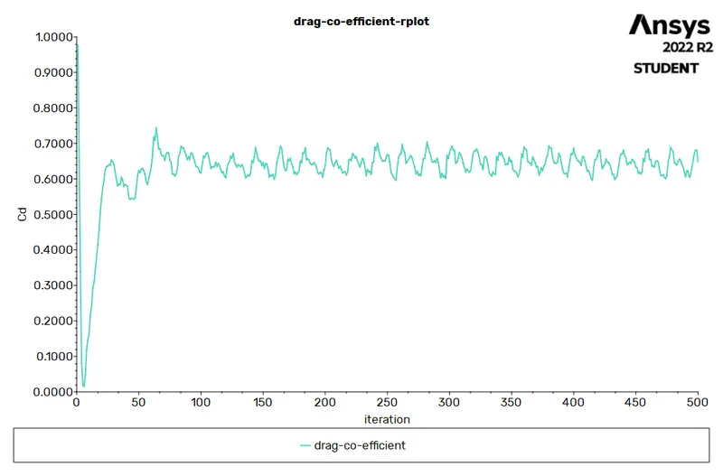
CO-EFFICIENT OF DRAG:
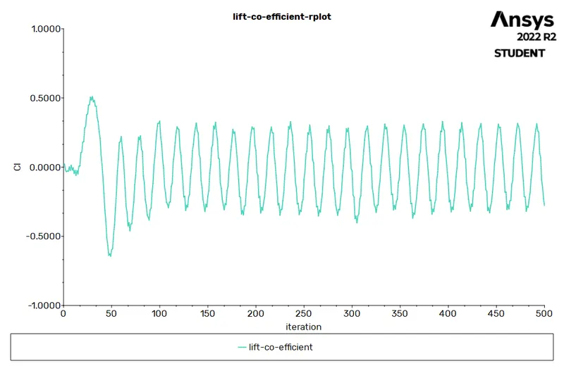
LIFT-COEFFICIENT:
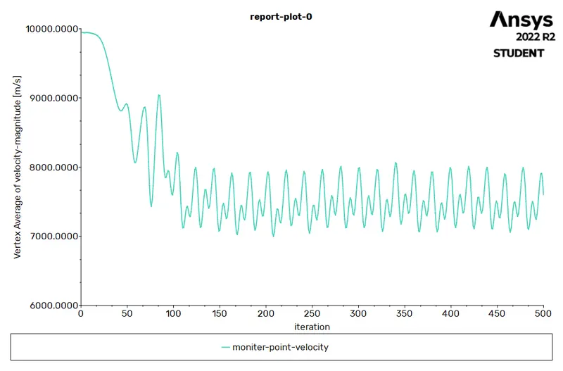
MONITOR POINT VELOCITY:
PRESSURE CONTOUR:
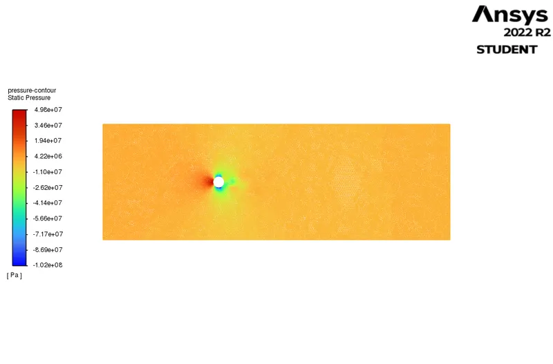
VELOCITY CONTOUR:
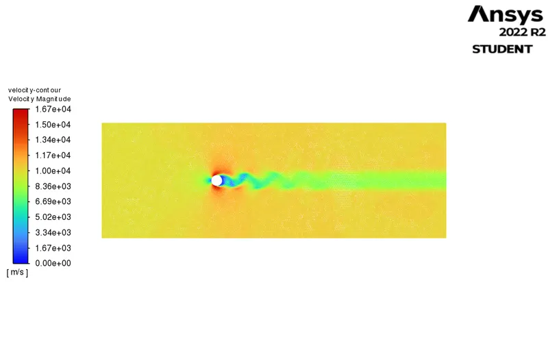
Unstaedy state solver:
Reynolds number = 100.
velocity = 10 m/s.
density = 1 kg/m3.
viscosity = 0.02 Pa-s.
RESIDUAL PLOT:
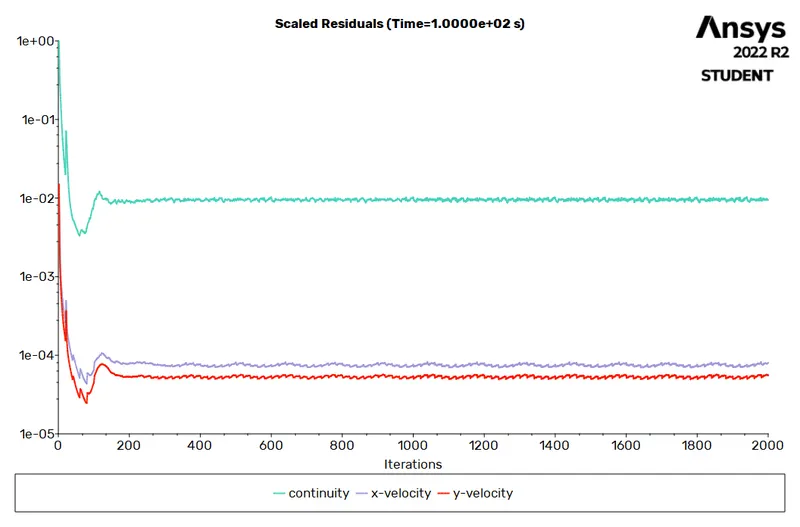
CO-EFFICIENT OF DRAG:
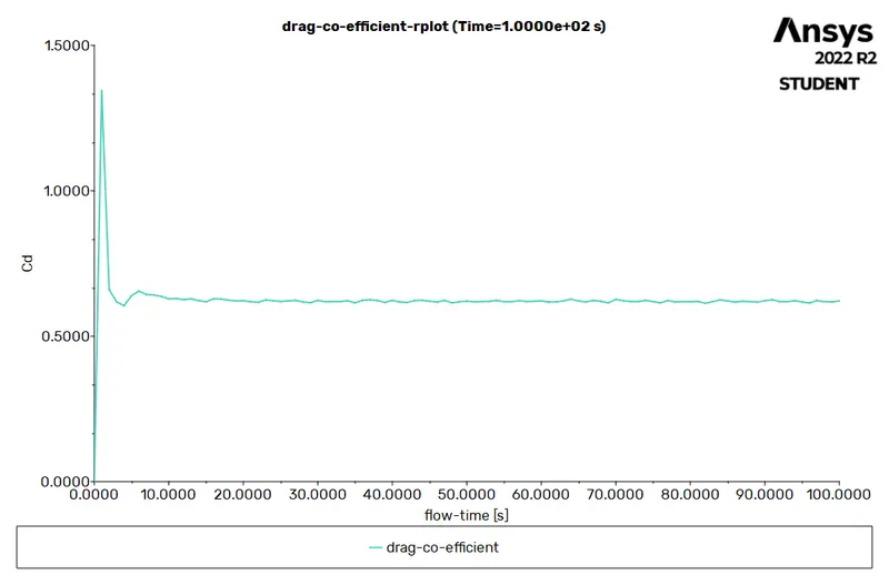
LIFT-COEFFICIENT:
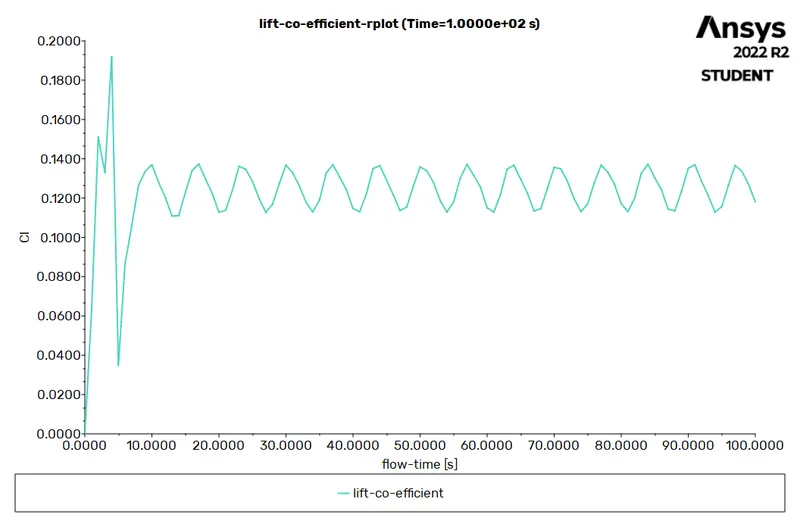
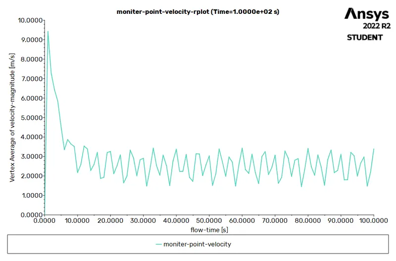
MONITOR POINT VELOCITY:
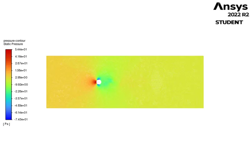
PRESSURE CONTOUR:
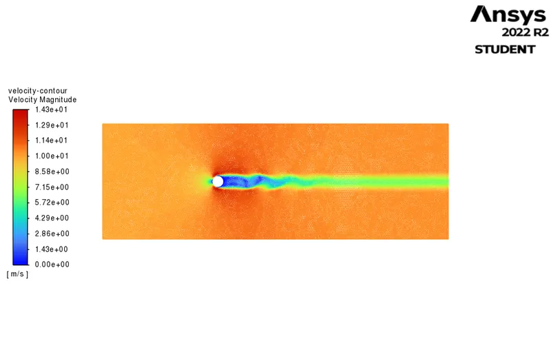
VELOCITY CONTOUR:
Strauhall number:
A strouhal number is a dimensionless number describing oscillating flow mechanisms.
The Strouhal number is often given as
St = f*d/u
Here,we have calculated starch no. using ansys fluent.
Go to fluent solver > results > fft analyzer> load lift coefficient> select plot FFT
Here, the x-axis denotes the strauhal number and the y-axis denotes magnitude.
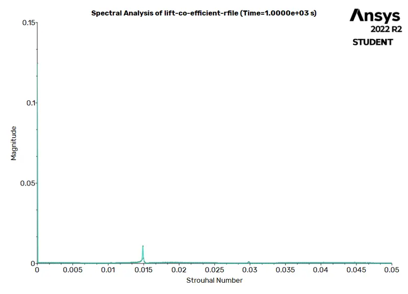
Strauhal Number = 0.015
Result:
Values of coefficient of drag and lift coefficient for respective Reynolds number is tabulated as follows:
| Reynolds NUMBER | CO EFFICIENT OF DRAG | LIFT COEFFICIENT |
| 10 | 1.3532 | 0.0878 |
| 100 -STEADY | 74.27 | 7.3887 |
| 100 -UNSTEADY | 0.6144 | 0.1132 |
| 1000 | 0.6790 | 0.0725 |
| 10000 | 0.5756 | 0.0313 |
| 100000 | 0.6539 | 0.2328 |