Week 2 - Flow over a Cylinder.
Aim:-
To simulate the flow over a cylinder and explain the phenomenon of Karman vortex street.
PART-I
- Simulate the flow with the steady and unsteady case and calculate the Strouhal Number for Re= 100.
PART-II
- Calculate the coefficient of drag and lift over a cylinder by setting the Reynolds number to 10,100,1000,10000 & 100000. (Run with steady solver)
- Discuss the effect of Reynolds number on the coefficient of drag. [ Results should be validated with any standard literature and error should be within 5 %]
Expected results:-
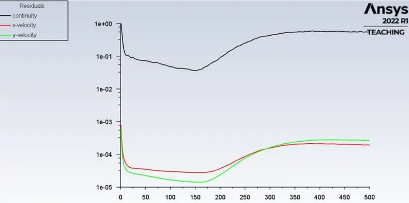
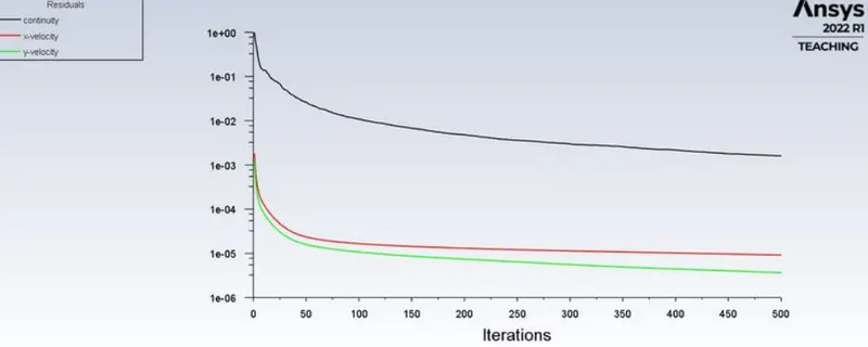
- In both approaches, show that the flow has converged. That is, what quantities or plots need to be looked at to determine that the flow has converged?
- Plots of the coefficient of drag and lift.
- Plots to show vortex shedding behind the cylinder.
Objective:-
- Simulate the flow with the steady and unsteady case and calculate the Strouhal Number for Re= 100.
- Calculate the coefficient of drag and lift over a cylinder by setting the Reynolds number to 10,100,1000,10000 & 100000. (Run with steady solver)
- Discuss the effect of Reynolds number on the coefficient of drag
- So The total number of cases is as below
- Case 1 – Re=10, Steady Flow
- Case 2 – Re=100, Steady flow
- Case 3 – Re=100, Laminar Flow
- Case 4 – Re=1000, Steady Flow
- Case 5 – Re=10000, Steady Flow
- Case 6 – Re=100000, Steady Flow
Introduction:-
Flow around objects exists from commonly observed movement of animals in nature such as the flight of birds ranging from the smallest in size to the largest to man-made applications viz., in heat exchangers, chimney stacks, and commercial and cargo flight aircrafts respectively and a growing significance to understand the different fluid flow phenomena like lift and drag coefficients, boundary layer separation, vortex shedding, etc., has been extensively exploited in recent years and in many cases to solve existing issues with the previously mentioned engineering applications. One such peculiar interest that gained importance over time was the flow around a circular cylinder and more specifically to comprehend the phenomenon of Karman vortex street which is when the wake behind the circular cylinder becomes unstable beyond a certain value of Reynolds number.
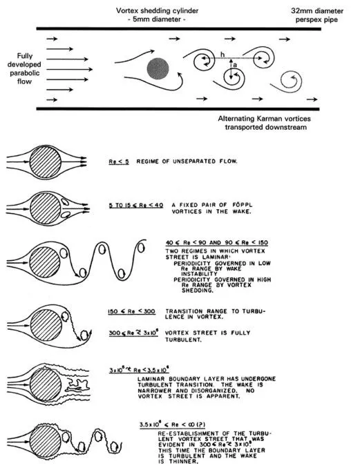
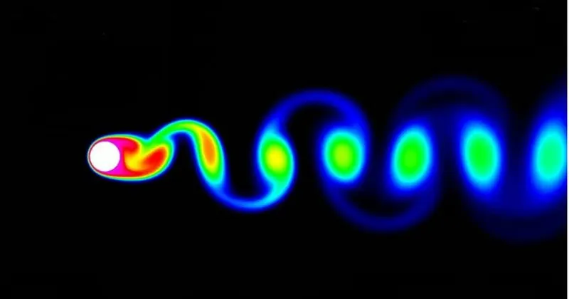
In this project, we are going to simulate the flow over a cylinder inorder to capture the vortex shedding that is formed behind the cylinder surface. This is done for various cases by varying the velocity of the fluid flow for each case inorder to change the reynolds number and so by taking the user defined fluid with constant density of 1 kg/m^3 and viscosity of 0.05 kg/m-s. This simulation is done with steady state and transient state for Reynolds number is 100 and so as to analyse the vortex formation for both the cases and also to calculate the Strouhal number.
Theory:-
1. Karman vortex:
In Fluid Dynamics, a Karman vortex street is a repeating pattern of swirling vortices, caused by a process known as Vortex Shedding, which is responsible for the unsteady separation of Fluid around blunt bodies. It is named after the engineer and fluid dynamicist Theodore Von Karman.
Vortex shedding is a phenomenon when the wind blows across a structural member, vortices are shed alternately from one side to the other, and where alternating low-pressure zones are generated on the downwind side of the structure giving rise to a fluctuating force acting at right angles to the wind direction.
Vortices are a major component of turbulent flow. The distribution of velocity, vorticity (the curl of the flow velocity), as well as the concept of circulation is used to characterize vortices. In most vortices, the fluid flow velocity is greatest next to its axis and decreases in inverse proportion to the distance from the axis.
2. Strouhal number:
In dimensional analysis, the Strouhal number is a dimensionless number describing oscillating flow mechanisms.
For large Strouhal numbers (order of 1), viscosity dominates fluid flow, resulting in a collective oscillating movement of the fluid "plug". For low Strouhal numbers (order of 10−4 and below), the high-speed, quasi-steady-state portion of the movement dominates the oscillation. Oscillation at intermediate Strouhal numbers is characterized by the buildup and rapidly subsequent shedding of vortices.
The Strouhal number is often given as
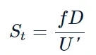
Where,
f= frequency of vortex shedding
D= characteristic diameter of the cylinder
U'= fluid flow velocity
3. Co-efficient of drag:
In fluid dynamics, the drag coefficient (Cd)
is a dimensionless quantity that is used to quantify the drag or resistance of an object in a fluid environment, such as air or water. It is used in the drag equation in which a lower drag coefficient indicates the object will have a less aerodynamic or hydrodynamic drag. The drag coefficient is always associated with a particular surface area.
The drag coefficient of any object comprises the effects of the two basic contributors to fluid dynamic drag: skin friction and form drag. The drag coefficient of a lifting airfoil or hydrofoil also includes the effects of lift-induced drag. The drag coefficient of a complete structure such as an aircraft also includes the effects of interference drag.
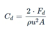
The drag coefficient(Cd)
is defined as
4. Co-efficient of lift:
The lift coefficient (Cl) is a dimensionless coefficient that relates the lift generated by a lifting body to the fluid density around the body, the fluid velocity, and an associated reference area. A lifting body is a foil or a complete foil-bearing body such as a fixed-wing aircraft. CL is a function of the angle of the body to the flow, its Reynolds number, and its Mach number. The section lift coefficient cl refers to the dynamic lift characteristics of a two-dimensional foil section, with the reference area replaced by the foil chord.
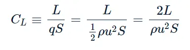
where
L is the lift force,
S is the relevant surface area and
q is the fluid dynamic pressure, in turn, linked to the fluid density, and to the flow speed.
5. Procedure:-
We are supposed to consider 2 cases for simulation,
Case 1) At Re = 100,simulate the flow with steady and transient method and calculate the Strouhal number.
Case 2) Compairing the fluid at steady case with different Reynolds number 10,100,1000,10000 & 100000.
GEOMETRY --> MESHING --> SETUP & SOLUTION --> RESULT.
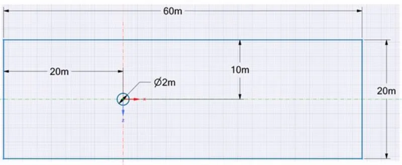
5.1. Geometry Creation :-
5.2. Meshing:-
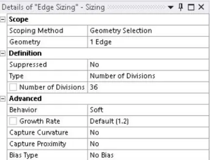
The generated 2D geometry meshed with element size of 0.25 m.The mesh was generated and proper inflation layers are given around the cylinder all to capture the wall boundary with growth rate of 1.2.Number of the generated elements is 39728.
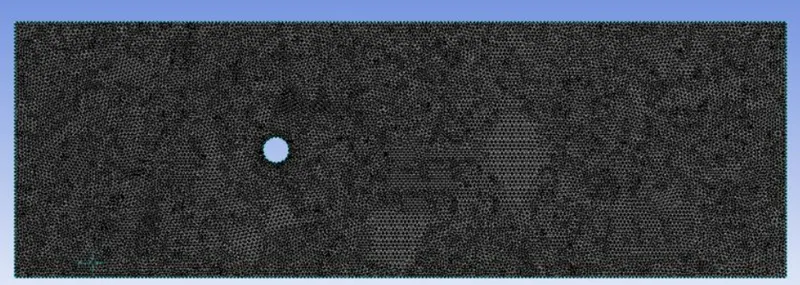
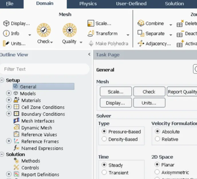
After the meshing and face naming are done move on to Fluent Solver. In the fluent launcher select double precision, display mesh after reading and give the appropriate solver processors and GPUs.
Fluent setup:-
|
SETUP |
STEADY-STATE |
UNSTEADY STATE |
|
SOLVER TYPE |
Pressure based |
Pressure based |
|
VELOCITY FORMULATION |
Absolute |
Absolute |
|
TIME |
Steady |
Transient |
|
VISCOUS MODEL |
Laminar |
Laminar |
|
MATERIAL |
User material |
User material |
|
CELL ZONES |
Fluid type: user material Density – 1 kg/m3 Dynamic viscosity – 0.02 kg/ms |
Fluid type: user material Density – 1 kg/m3 Dynamic viscosity – 0.02 kg/ms |
|
BOUNDARIES |
Velocity magnitude 1m/s
Gauge pressure – 0 pa
Condition - No slip |
Velocity magnitude 1m/s
Gauge pressure – 0 pa
Condition - No slip |
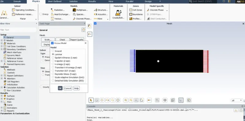
In the ANSYS CFD we need to give all the conditions, parameters and models. To start with go to physics menu and click general settings. In that select Pressure based type solver, Absolute velocity formulation and steady state flow. Next we need to give the model. For this case Laminar is selected.
6.Solution:-
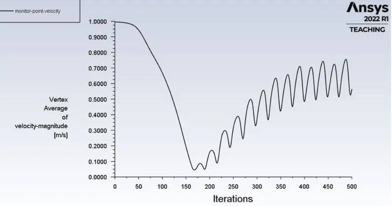
- Vertex average of velocity magnitude using surface report at a monitor point at 10m from the center of the cylinder to the right of the cylinder along the x-direction.
- Coefficient of drag and coefficient of lift reports are created using force report
- Initilization: Hybrid for steady state
The standard for unsteady state
- Activities: contour plots of pressure and velocity and solution animation are created after initialize the solution.
- Run Calculation:
For steady-state – No of iterations= 500
For transient state – Time step = 0.1
No of iterations = 500
Next is the flow material selection. By default air is selected. Density and viscosity are given.
Next the boundary conditions of the inlet and other are set as per the problem statement. For the first case the velocity of the inlet is set to 0.25m/sec.
After the physics part is done move to the solution part. Initialise the simulation first. click Initialize to initialize the boundary conditions. Hybrid method is selected before initialization. Click on Autosave to obtain a animation of the flow in the post results.
Then run the calculation for a given number of iterations till the convergence is obtained. Depending upon the number of elements and model selected the time required for convergence varies. In the CFD module itself we can compute, measure, plot, animate, etc., if needed. After the solutions and calculations move to the result module to get different graphs, plots, contours, animations etc.,. Sectional views can be created if required.
Contour Velocity
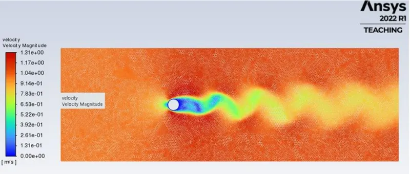
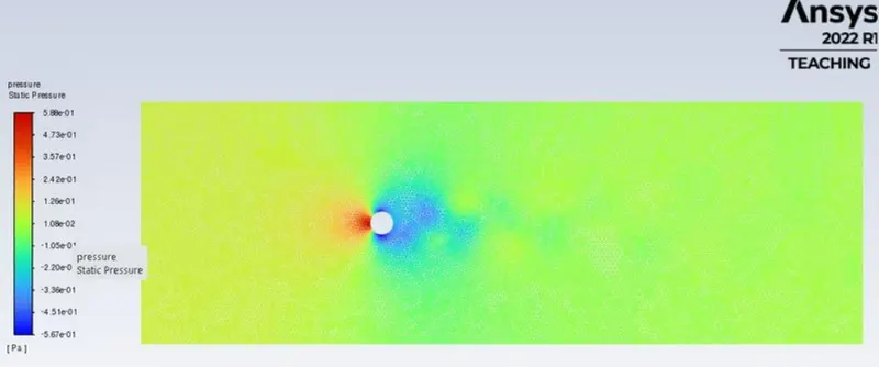
Case 2 Re = 10:-
U=0.1m/s
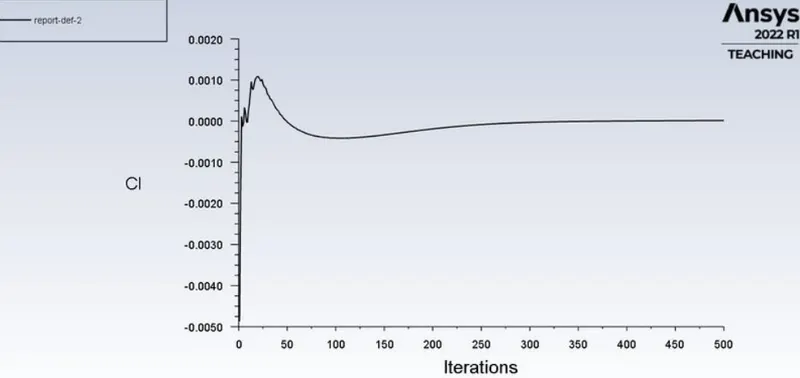
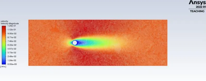
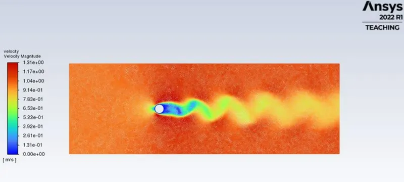
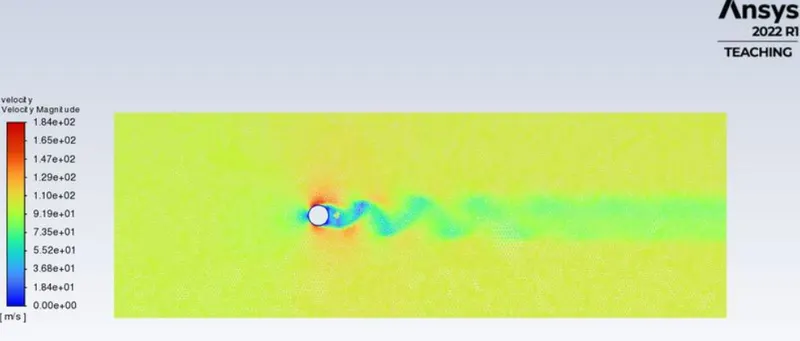
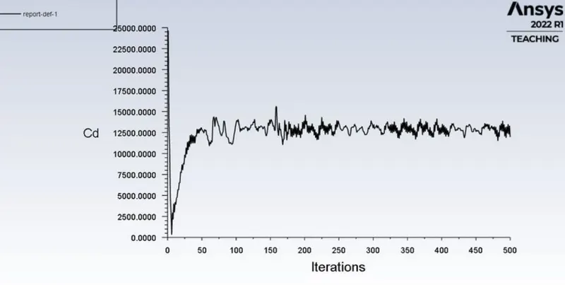
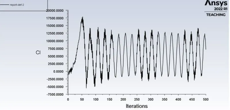
From the above plot, we can say that the value of the lift coefficient keeps on increasing as we keep increasing the velocity and Reynolds number. The drag coefficient is maximum for the lowest Reynolds number and goes on decreasing.
Conclusion:-
When fluid flows over the cylinder, the wake region is formed next to the cylinder due to a decrease in pressure, and recirculation of flow occurs hence flow separation occurs.
As flow over a cylinder is transient we are unable to observe flow separation at a low Reynolds number
As the Reynolds number increases the coefficient of drag decreases.
Strauhal number for an unsteady state with Reynolds number 100 is 0.01.
References:-
B.N. Rajani, A. Kandasamy, Sekhar Majumdar,
Numerical simulation of laminar flow past a circular cylinder,
Applied Mathematical Modelling,
Volume 33, Issue 3,
2009,
Pages 1228-1247.