Week 2- 2R Robotic Arm Challenge
% A program simulation for a 2R Robotic Arm

clear all
close all
clc
% Inputs
l1 = 0.8;
l2 = 0.5;

theta1 = linspace(0,90,8);
theta2 = linspace(0,90,8);

ct = 1;
for i = 1:length(theta1)
THETA1 = theta1(i);

for j = 1:length(theta2)
THETA2 = theta2(j);

x0 = 0;
y0 = 0;

x1 = l1*cosd(THETA1);
y1 = l1*sind(THETA1);

x2 = x1 + l2*cosd(THETA2);
y2 = y1 + l2*sind(THETA2);

%plotting

plot([x0 x1],[y0 y1],[x1 x2],[y1 y2],'linewidth',3.5);
axis([-0 1 0 1.5]);
pause(0.02);

M(ct) = getframe(gcf);

ct = ct+1;

end;

end;

movie(M);
videofile = VideoWriter('2R_robotic_arm.avi', 'Uncompressed AVI');
open(videofile);
writeVideo(videofile,M);
close(videofile);
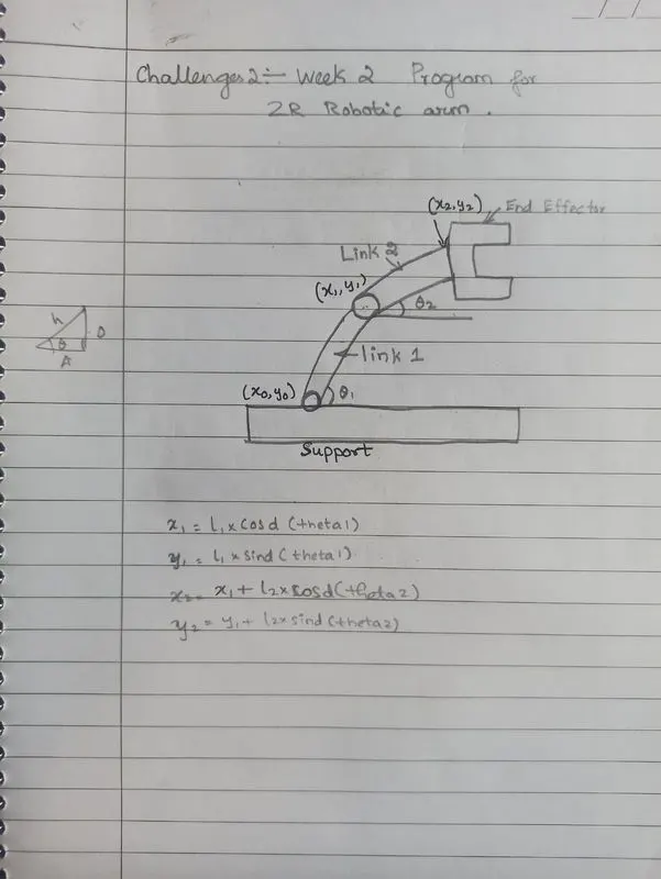
Explanation:
The robotic arm is the same as like human arm so it can use in industrial machinery and manufacturing sectors.
The arm could be the entire device or it might be a component of a more sophisticated robot. Such a manipulator has joints connecting the linkages that provide rotational motion or translational displacement. A kinematic chain may be thought of as being formed by the manipulator's linkages. The end effector, which is similar to the human hand, is the culmination of the manipulator's kinematic chain. Forward kinematics is the process of using a robot's kinematic equations to determine the end-location effector's given provided values for the joint parameters.
Command explanation:
1. Both links' lengths are used as input. Link-1's length is assumed to be 0.8 m, while link-2's length is assumed to be 0.5 m.
2. Links 1 and 2's angles that were traced by both links are used as input.
3. To mimic the movement of the robotic arm, a range of angles are drawn.
The range of angles tracked by both linkages is then iterated through using two for loops.
Link-2 is moved throughout its range for each specific angle of link-1 in order to achieve various end effector locations.
These equations compute the end location of link-1 and link 2:
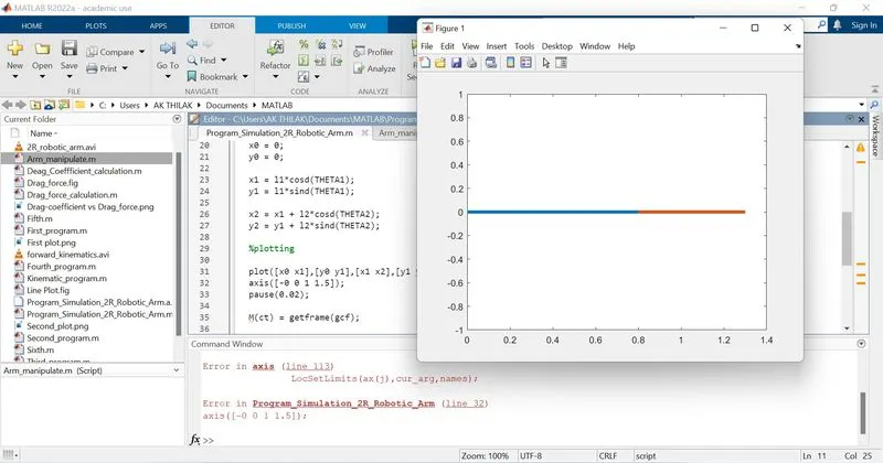
https://drive.google.com/file/d/1dXfwD4ThQcAl91OEbugjNzfMcsm3d87d/view?usp=sharing